Gear shifting
The fun part of the engine overhaul: Playing with the gear shifting
This weekend I have mounted the gear assembly. First I study the drawing in the service manual, spare parts manual, Haynes and Clymer workshop manuals, looked all over again.. ??? Perhaps I’m stupid or something, but I don’t get it. After the mounting process and playing with the gear shifting I think I have some answers.
Let’s go back and take one step at a time:
Step 1:
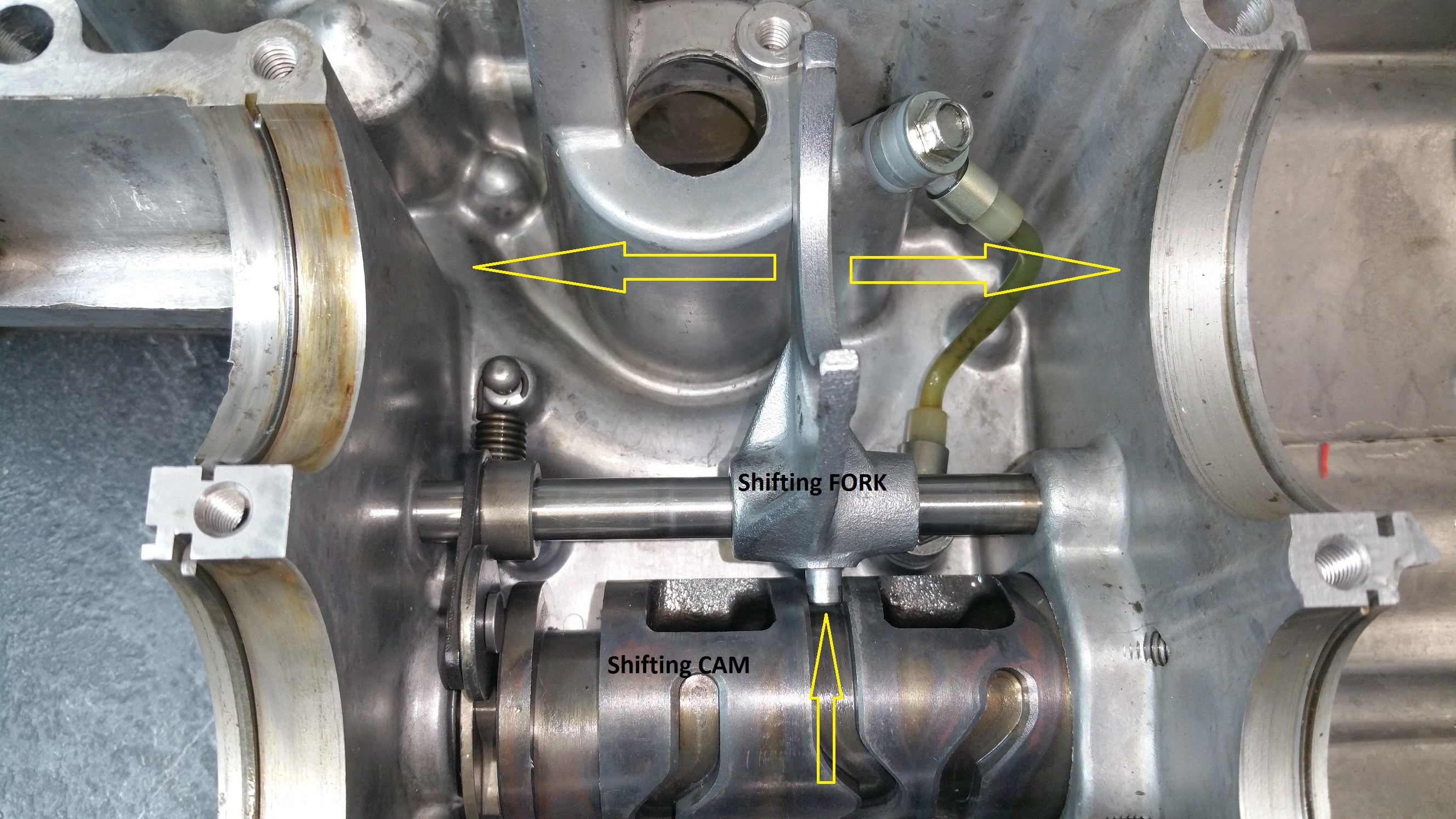
Look at the picture below. While shifting gear the CAM will rotate, and as you can see, the shifting FORK is fixed in the groove and will be moved to left or right depending of the track pattern in the shifting CAM
The gears are mounted on top of the forks and will therefore be moved according to the tracks in the CAM.
For detailed information about mountig the CAM and FORK, please look at my privious post ” Mounting the cam for the gear shifting”
Step 2:
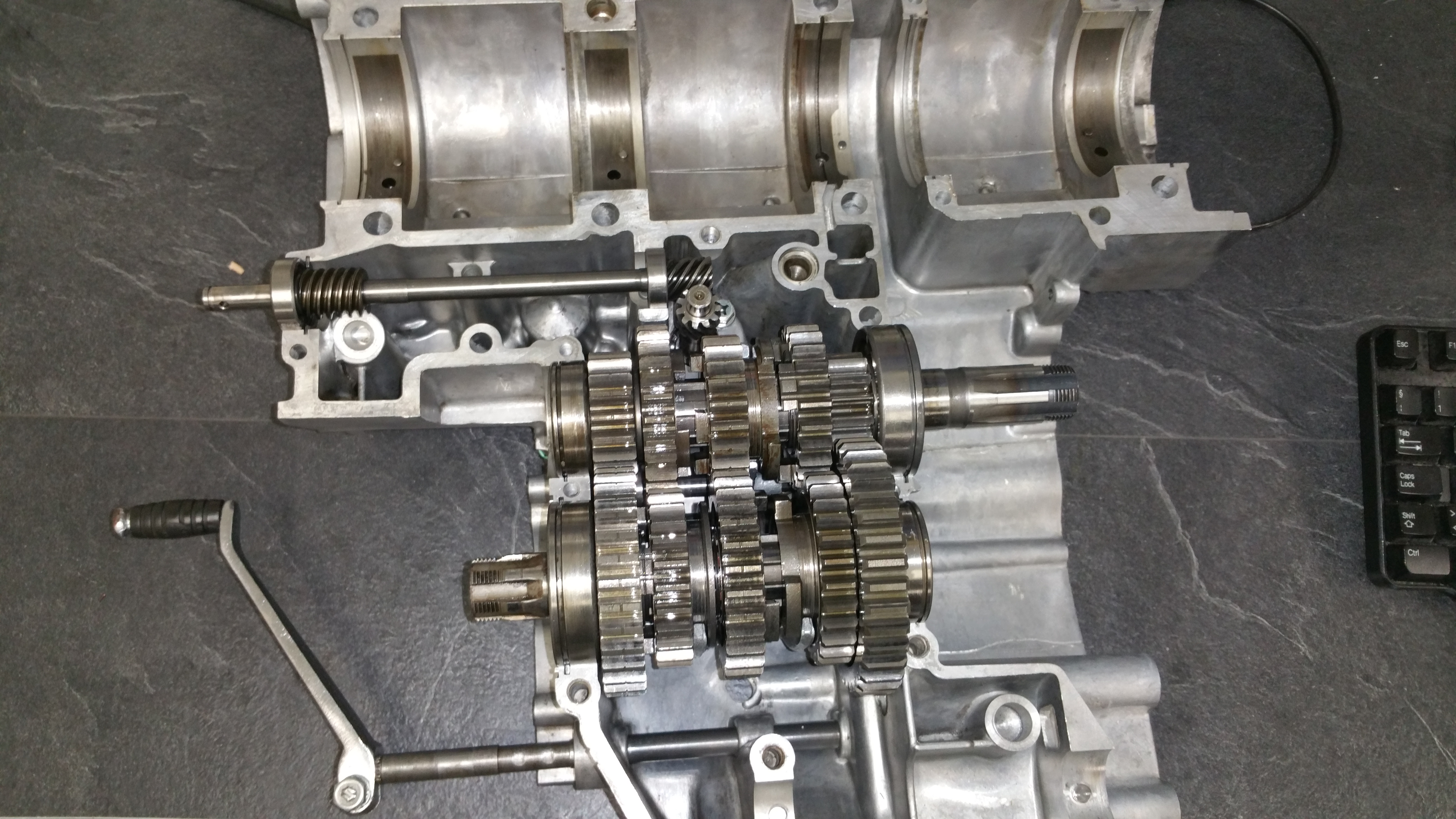
Mount the gear assembly according the the first picture on this post. Remember to mount the all C-rings for locking the gear shaft. Slide the front and rear gear assembly down into the forks.
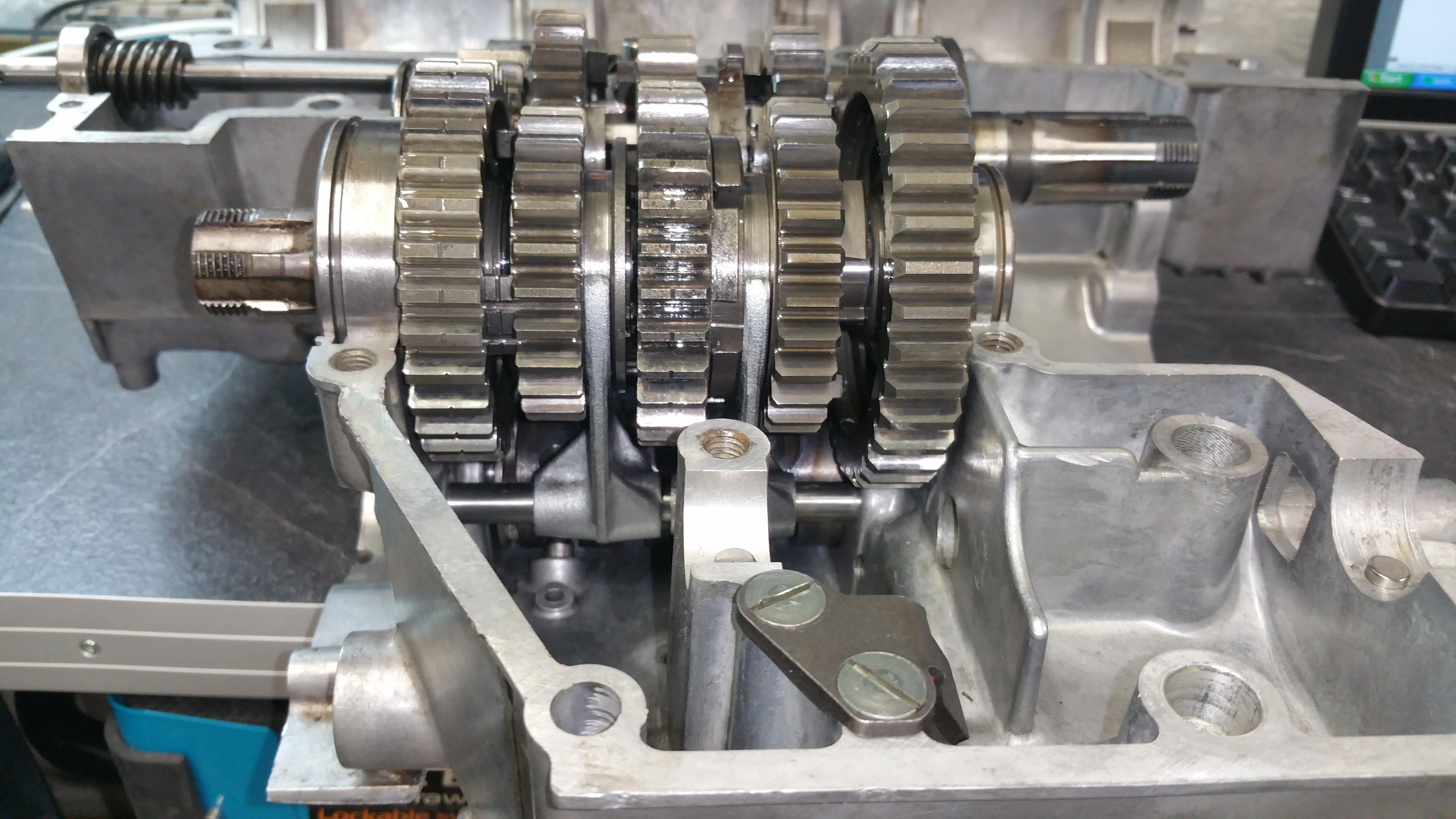
Rear assembly, notice the position of the forks. Rotaton of the CAM will slide the gears to left or right.
Step 3:
Mount the CAM stopper:
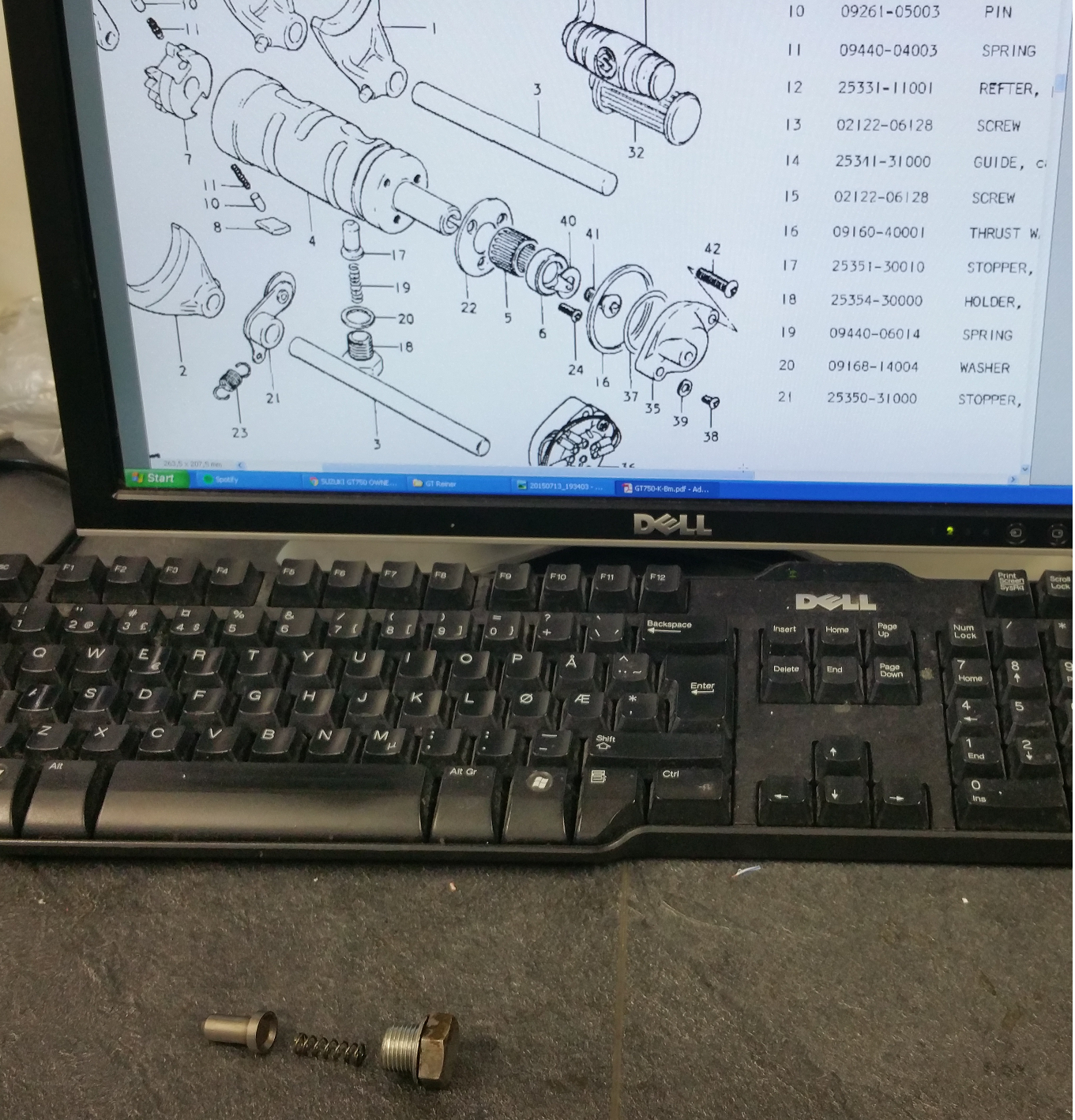
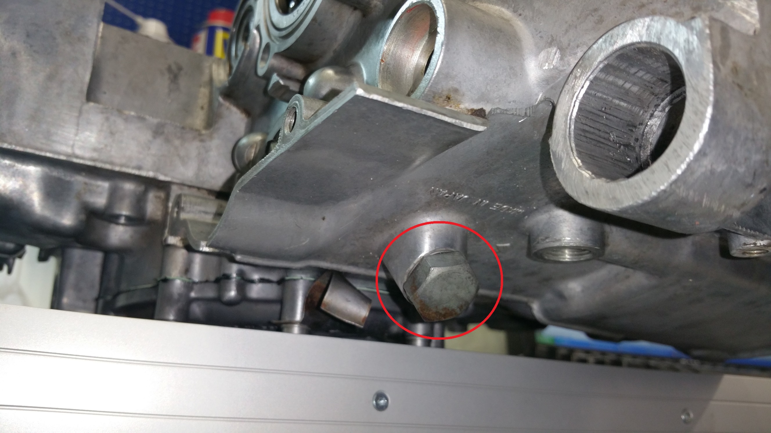
The spring loaded CAM stopper (items 17-20 on the drawing) will prevent the cam to rotate out of its correct position.
Step 4:
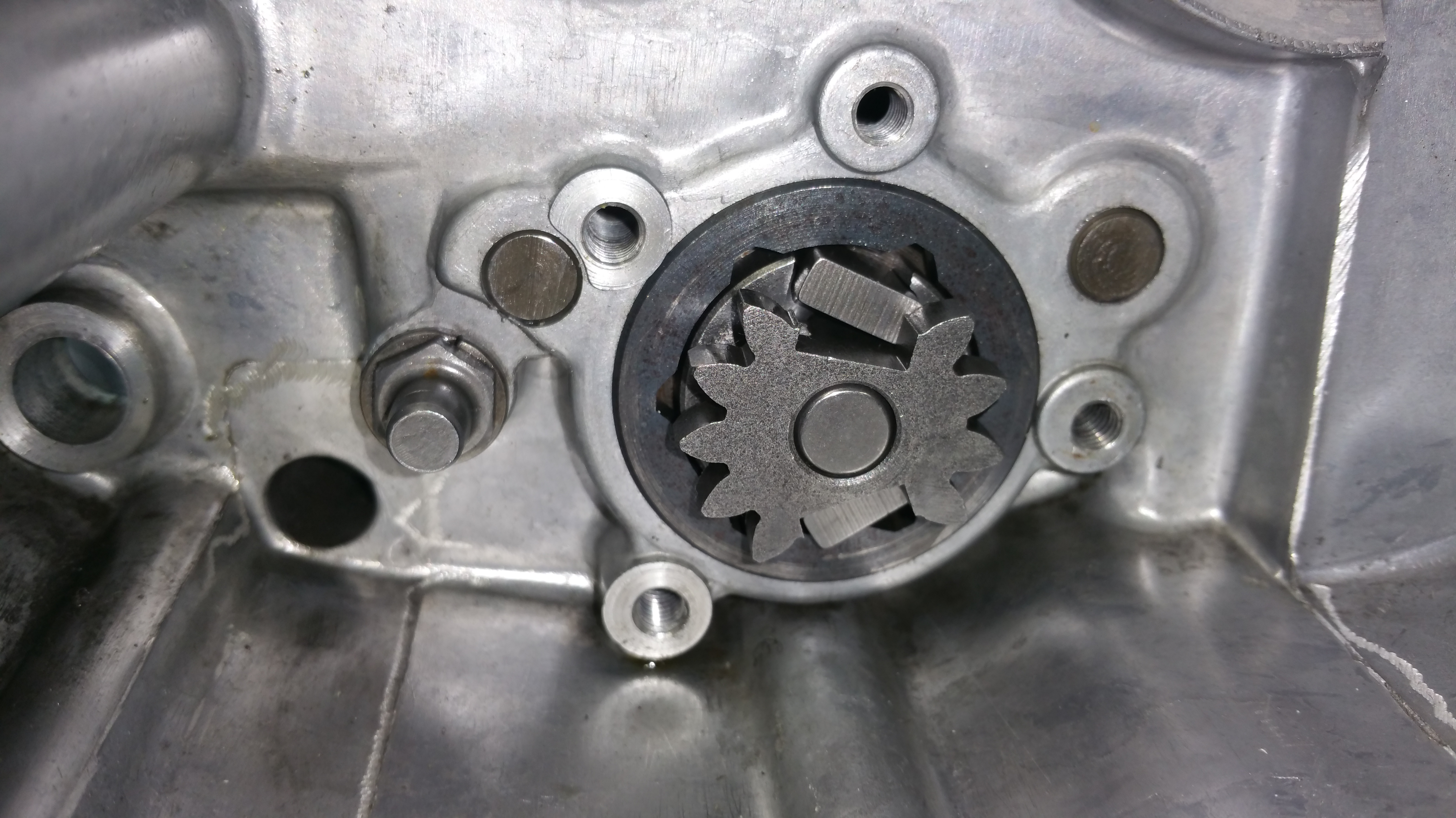
How do we rotate the CAM ? We all know we are kicking the gear shifter down into the lowest 1-gear and upwards for the higher 2-5 gears. But how does the CAM rotate all the way ?
Shifting down:
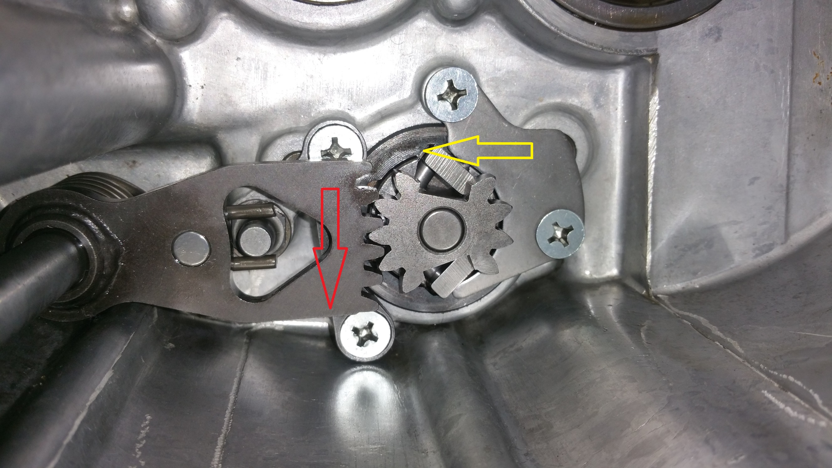
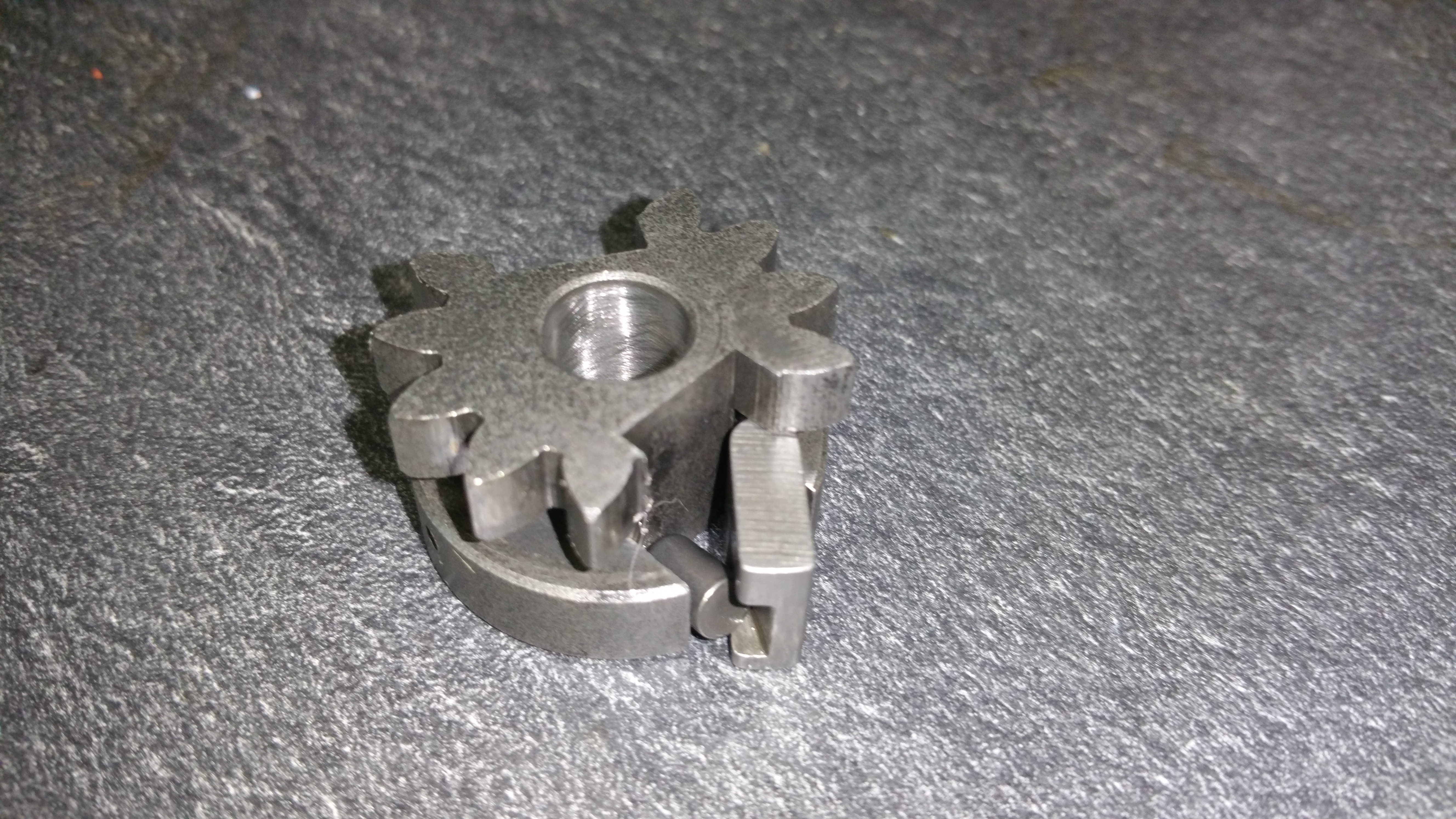
Shifting down, the movement follow the red arrow og the rotation of the cam the yellow arrow. The upper little metal part is spring loaded and will be pushed by a tiny little piston into a cut out in the CAM. In this position it’s locked and will move the entire CAM to a left side rotation in the picture.
When you release the pressure from the gear shifter the spring loaded mechanism will return to right and grab into a new cut out, ready for a new rotation.
Shifting up:
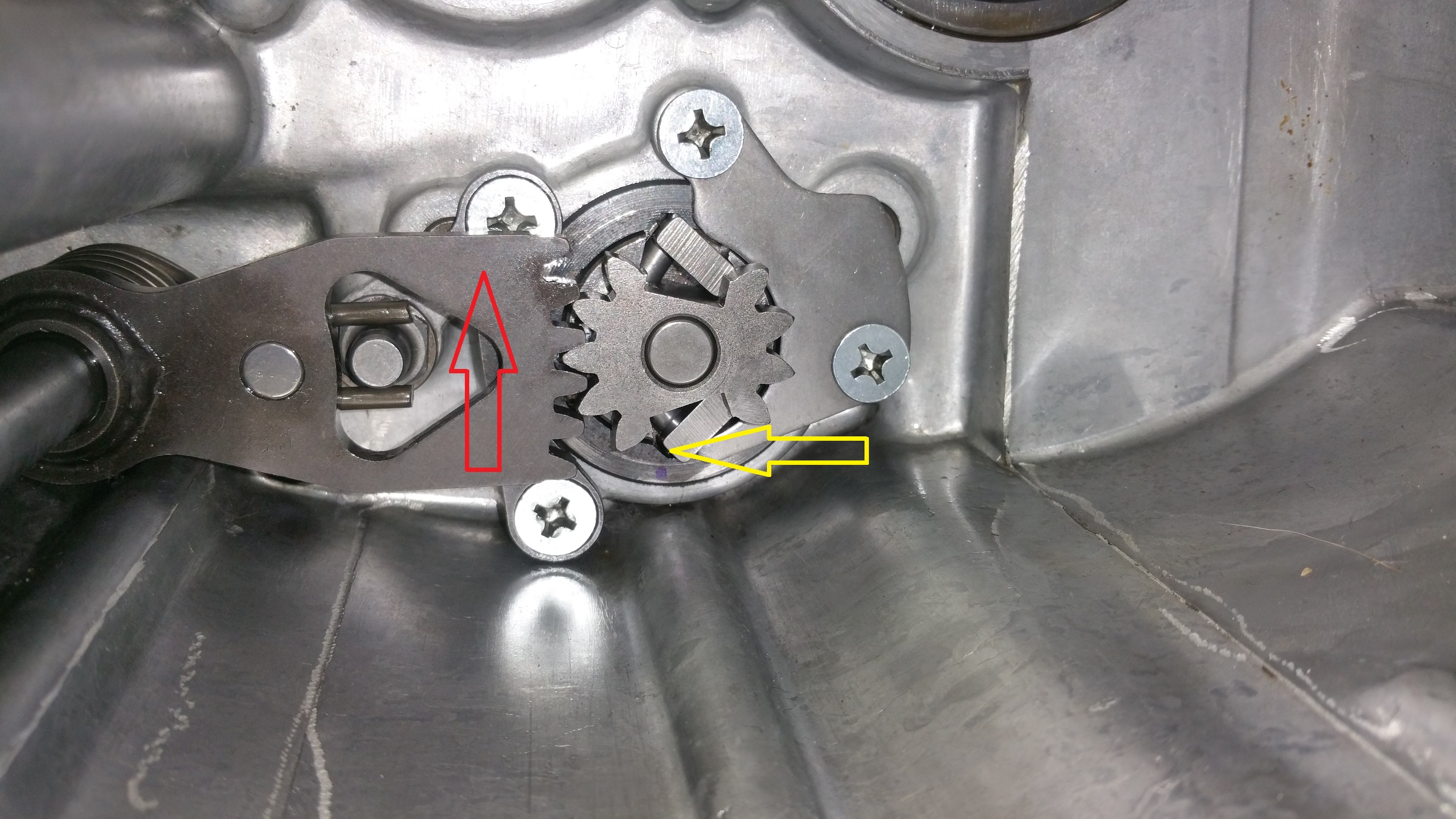
Same explanation as above but opposite direction.
The spring loaded mechanism in details:
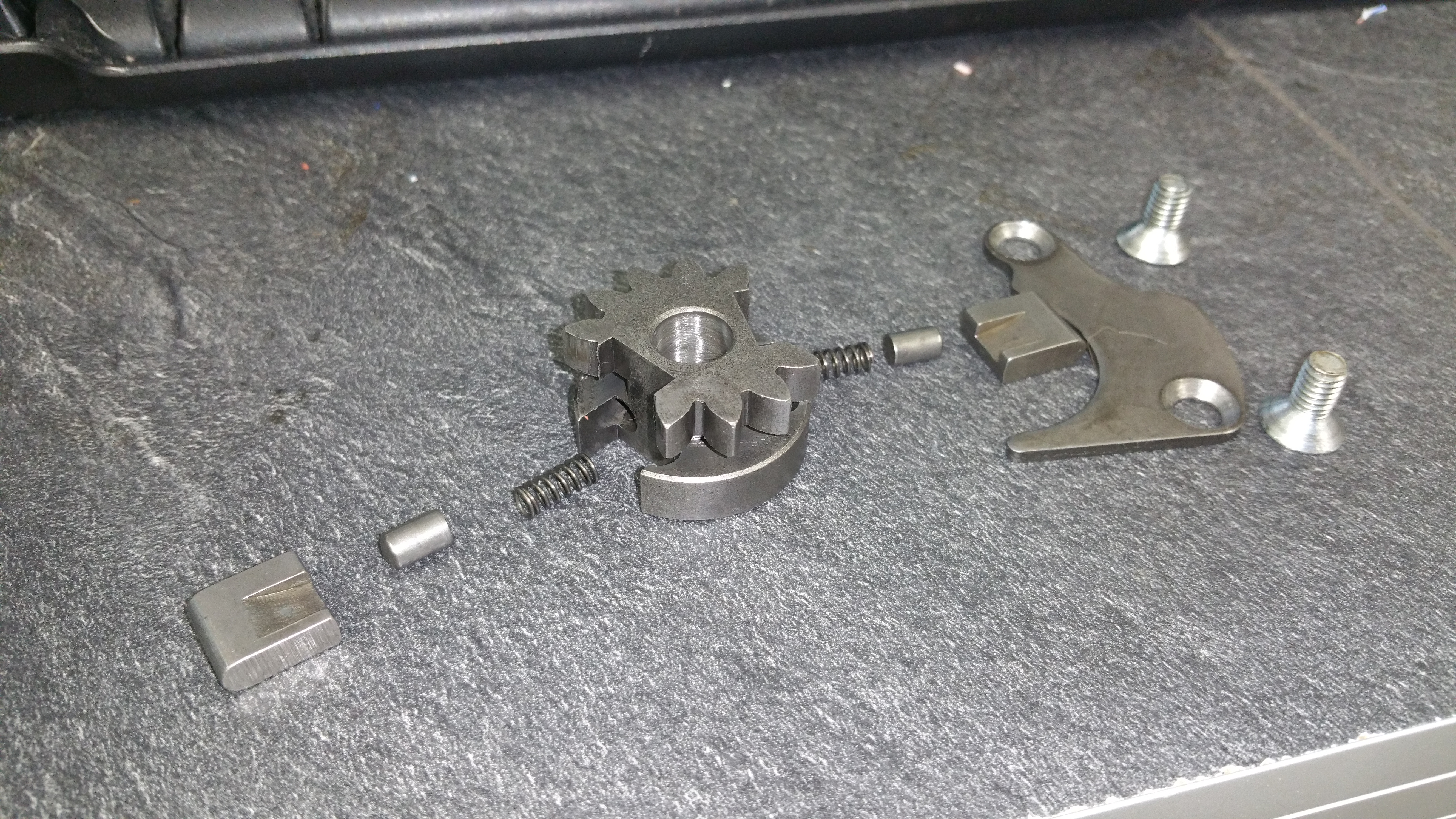
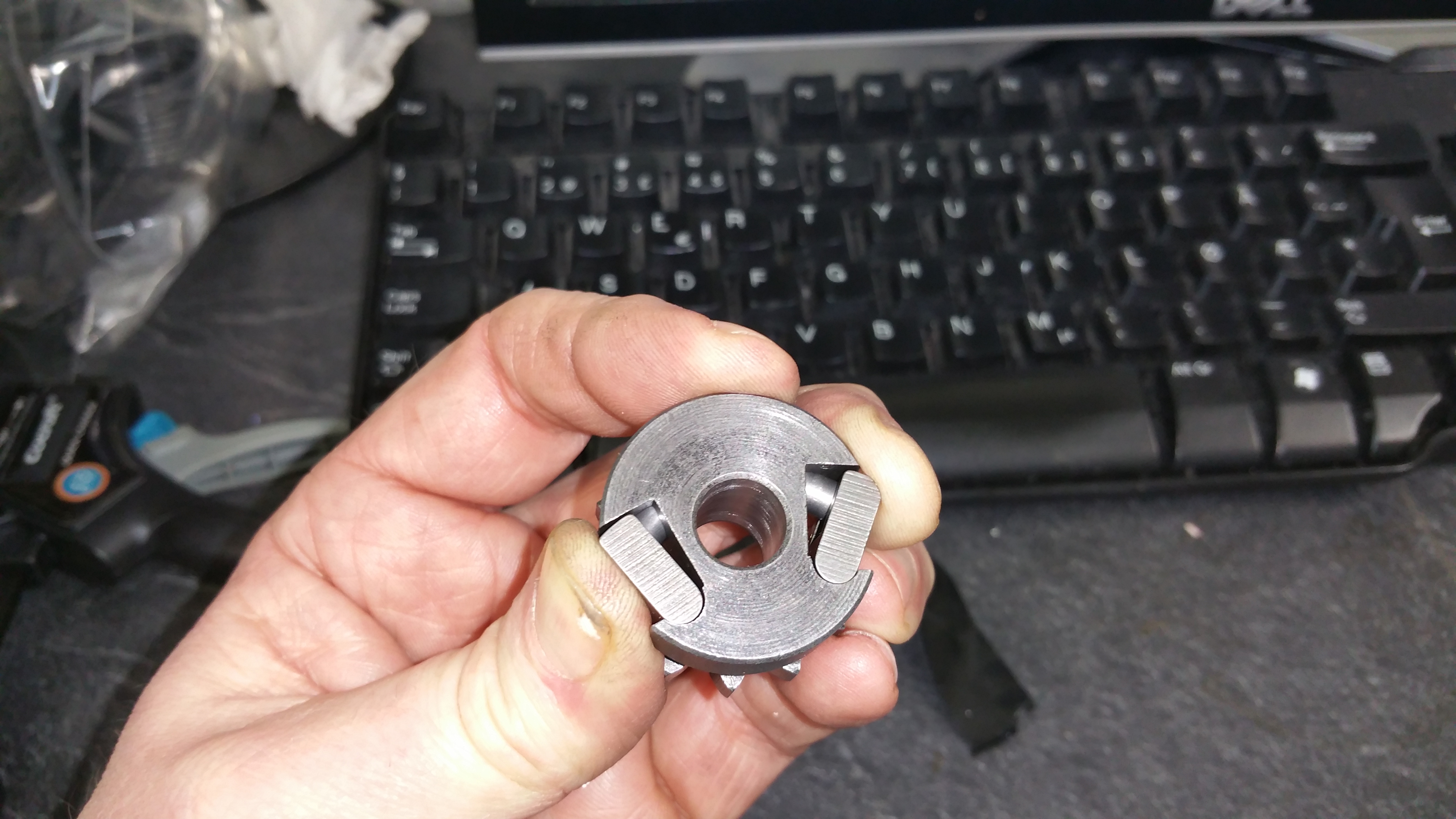
A bit tricky to keep all parts in position before mounting.
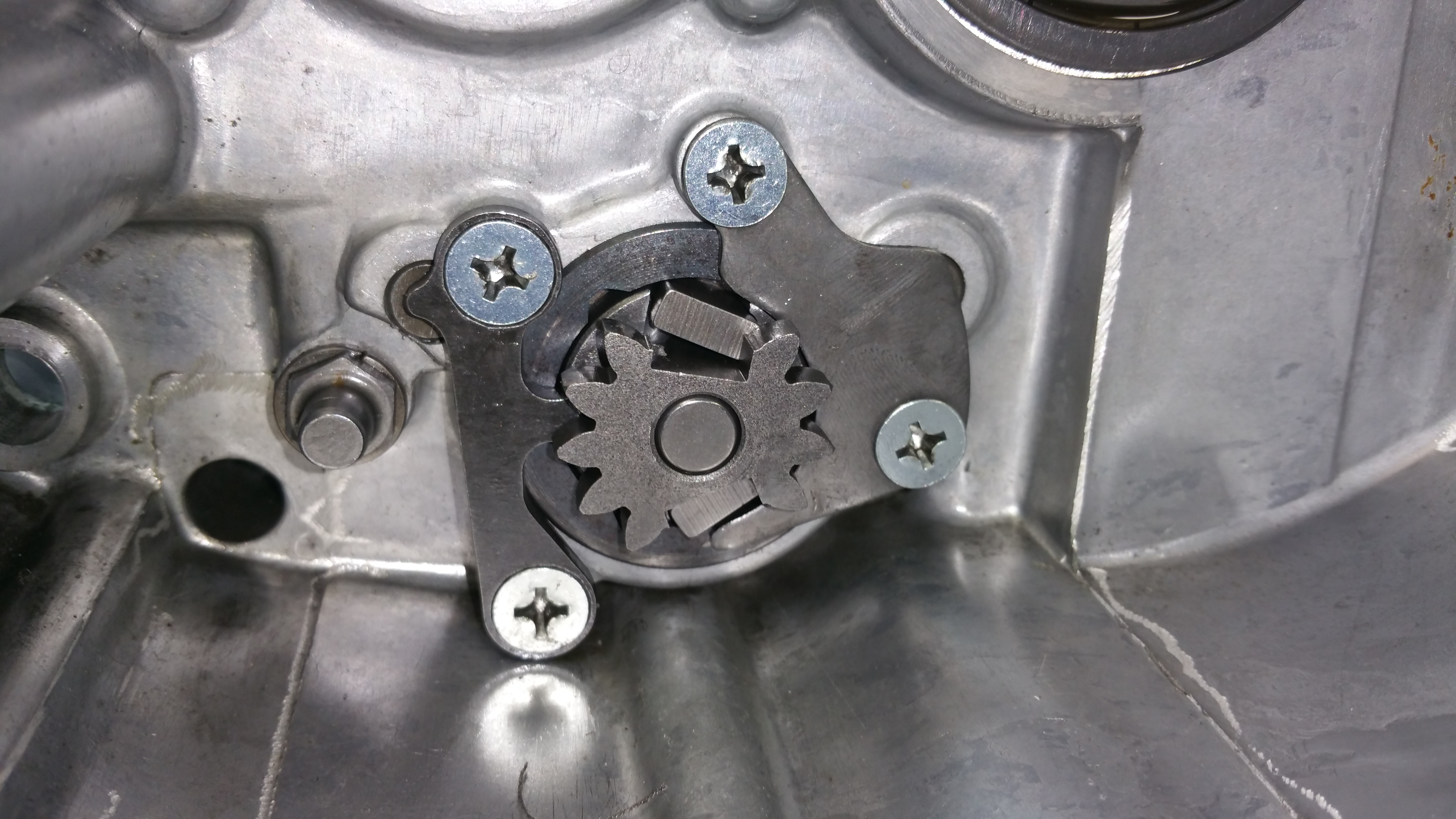
Mount the brackets and use thread lock on the screws.
Step 5:
Check the gear shifting:
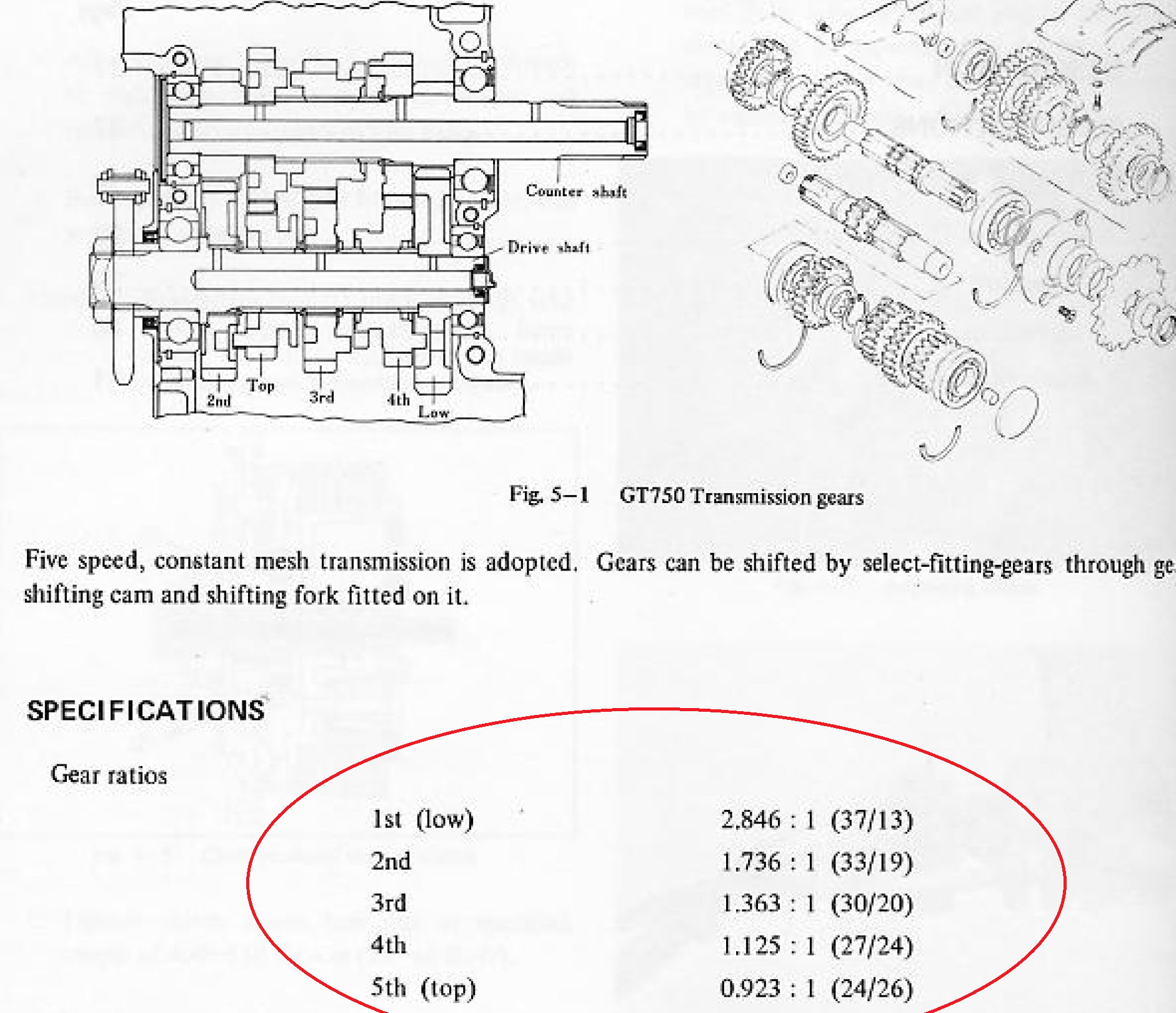
The table above shows the gear ratio. I put a piece of tape on the outgoing axle aligned to the mark on the incoming axle from the clutch.
1-gear
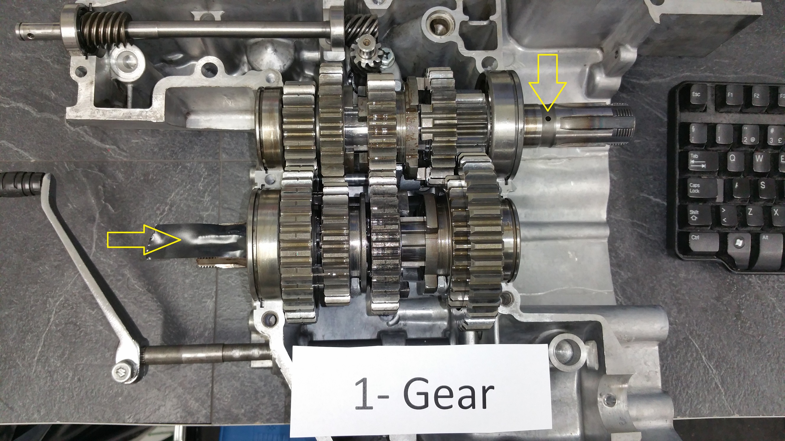
By counting the revolution on the incoming axle for one turn on the outgoing axle I got the same ratio as in the specifications. Almost three turns (2,8) in the 1-gear position for one revolution at the outgoing.
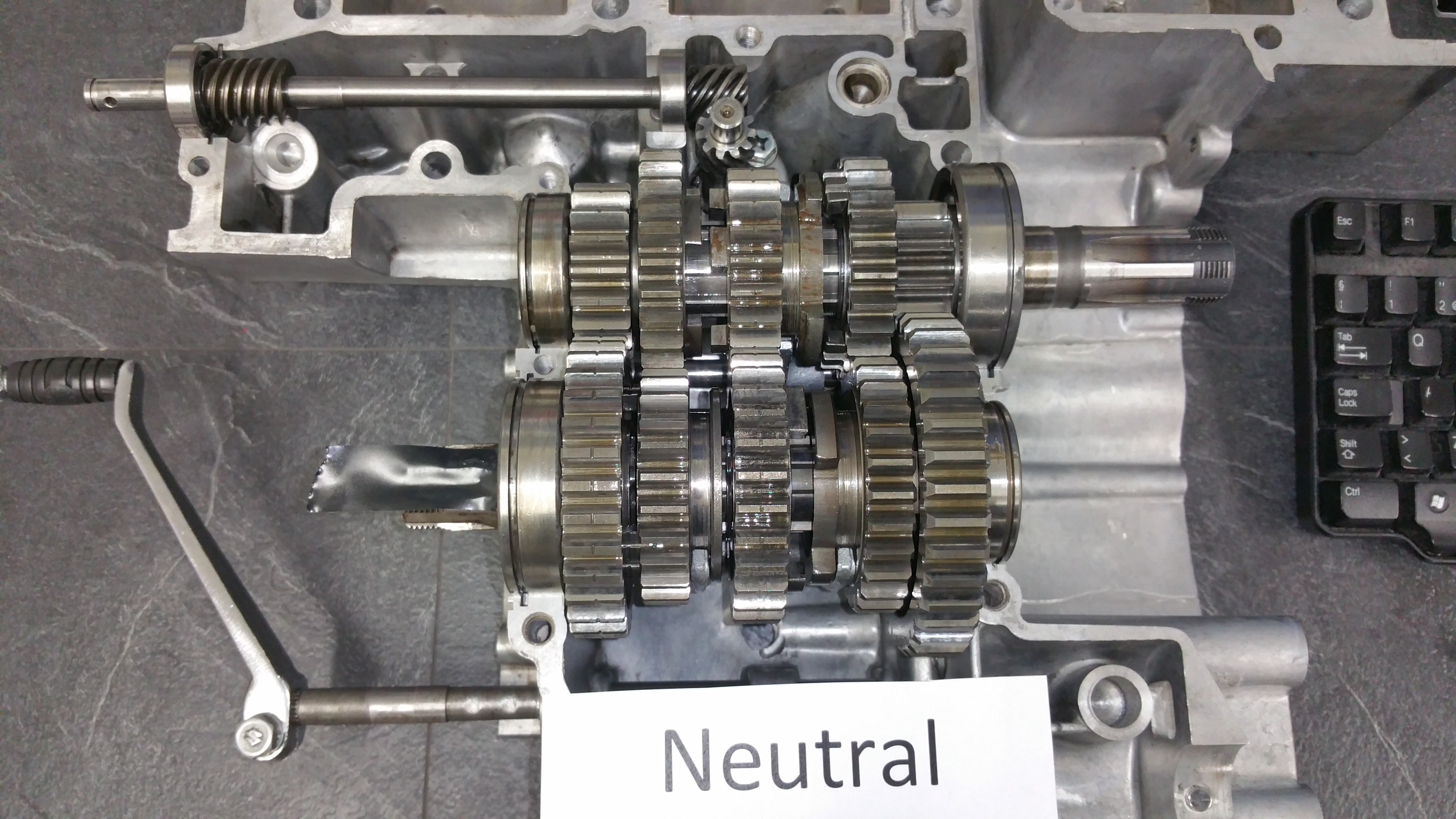
Neutral position:
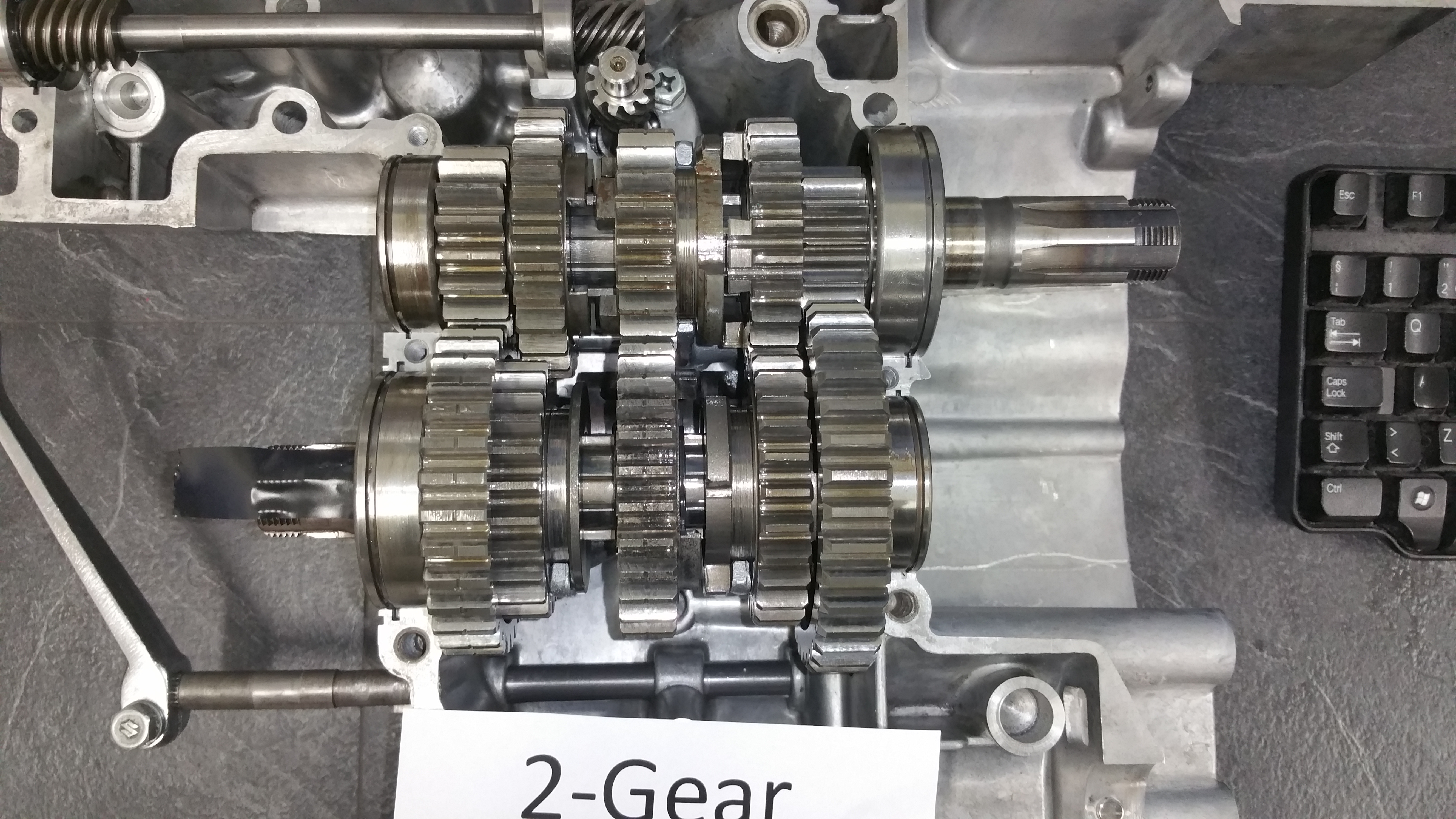
2- gear. Ratio of 1,7:
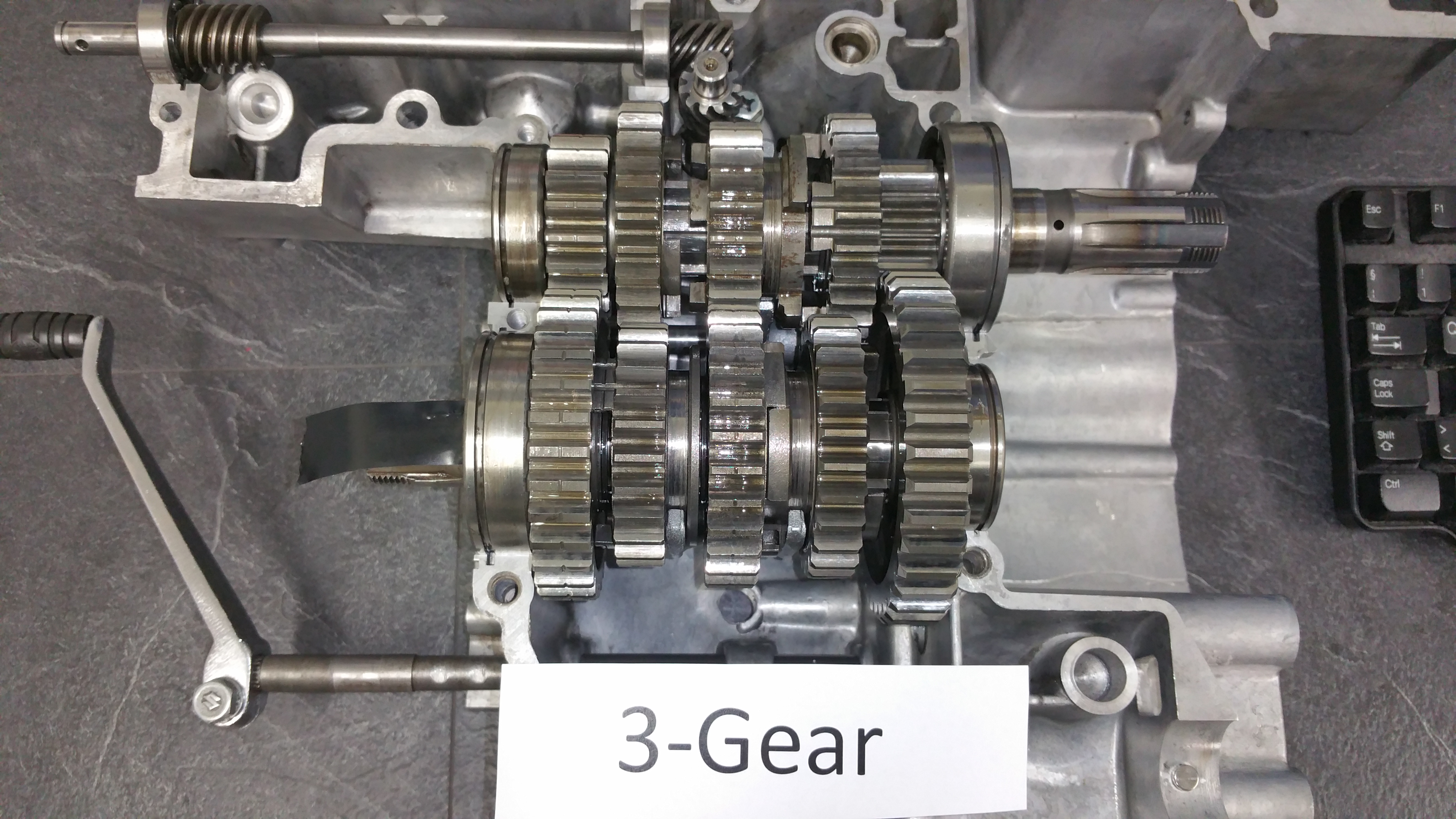
3-gear. Ratio of 1,3:
4-gear. Ratio of 1,1:

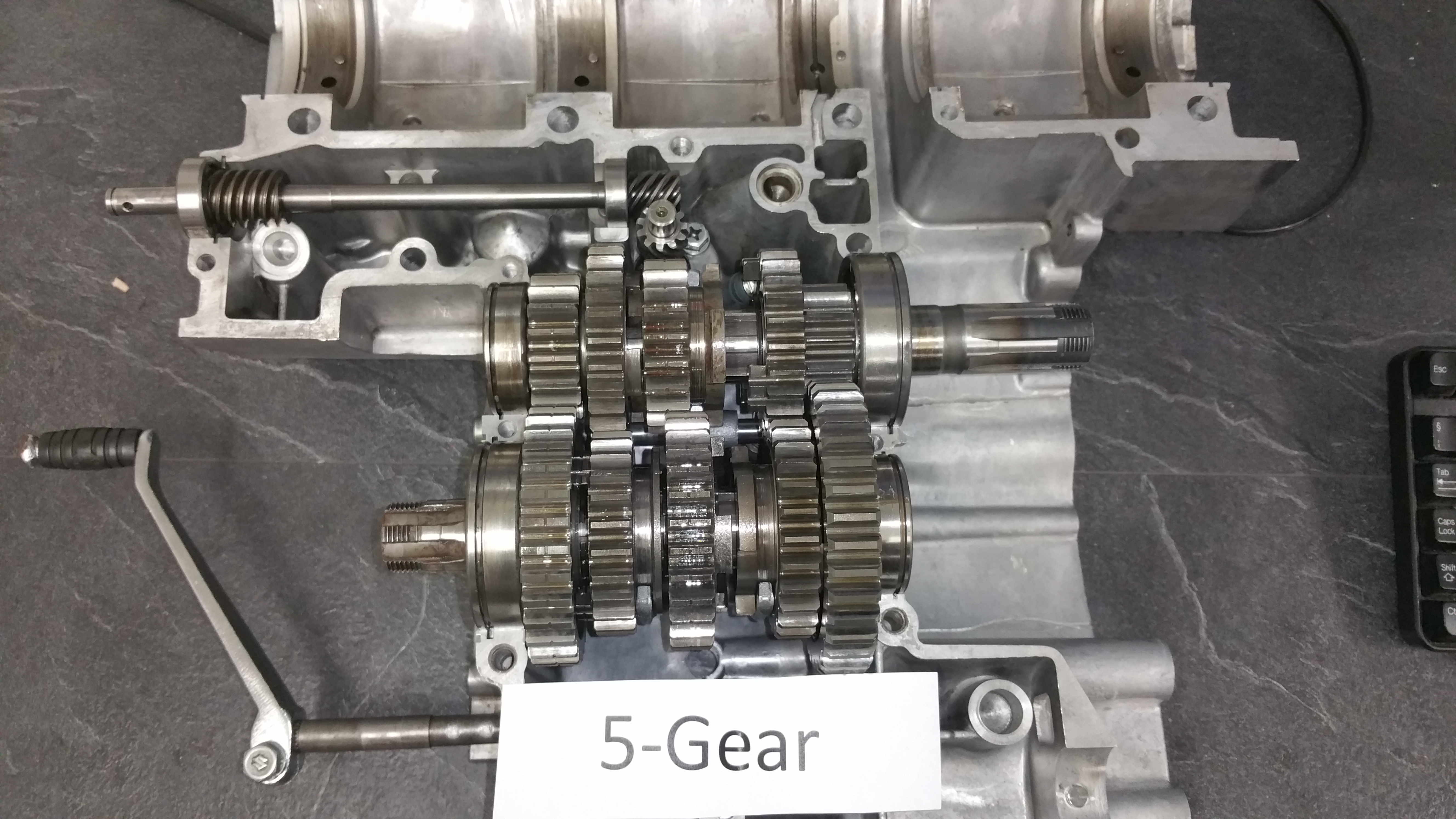
5-gear. Ratio of 0,9
All gears are shifting according to the specifications. It would be stupid to proceed with the assembly without checking the gear shifting.
The gearbox is not without any worn parts. Based on the experience before dismounting it still shifts smooth and nice without any problems at all. I dont’ want to spend money and work on parts if it’s not needed.
I can sleep well tonight 🙂