GT Friday ride part 2
Before starting the disassembly process.
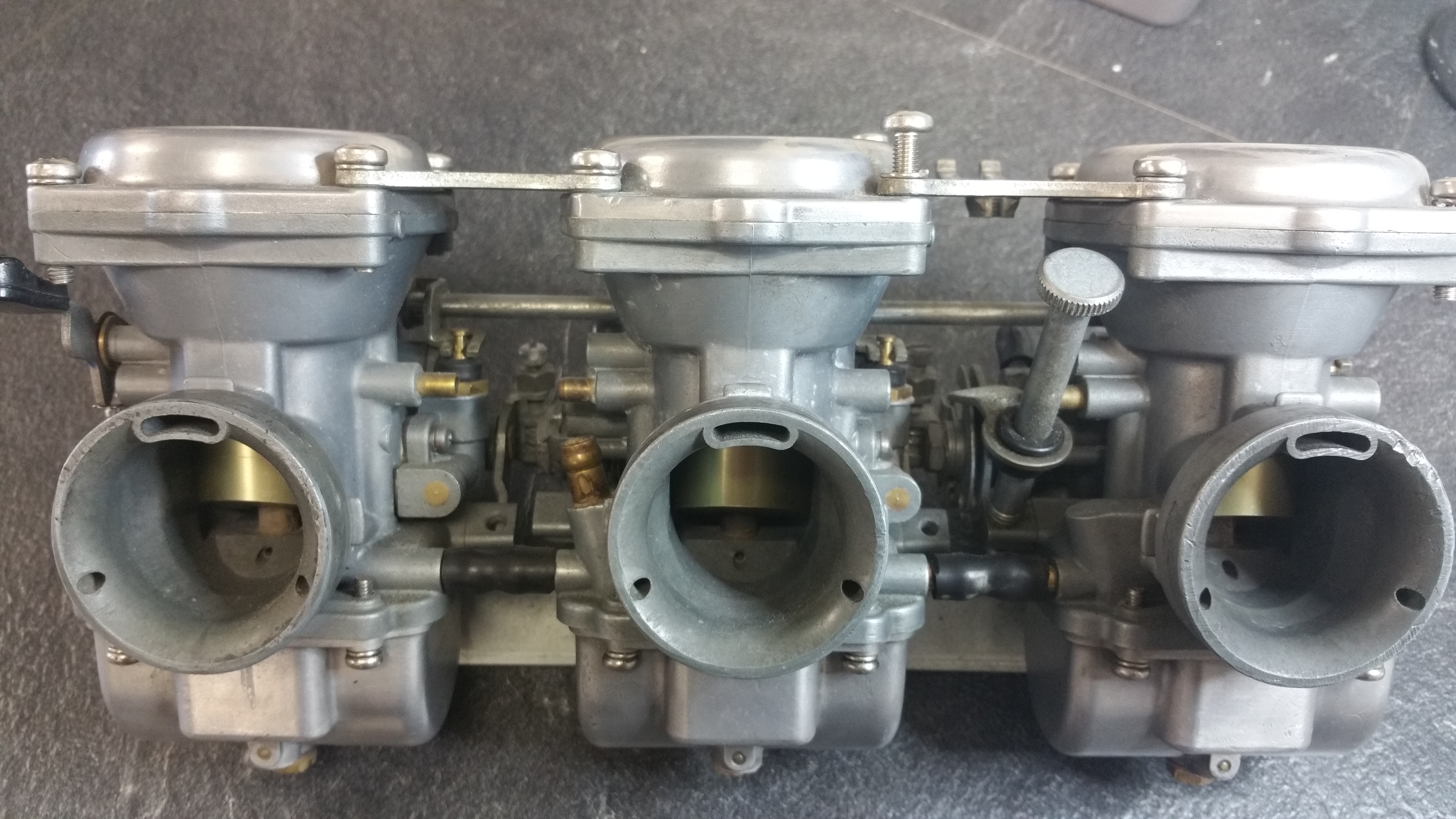
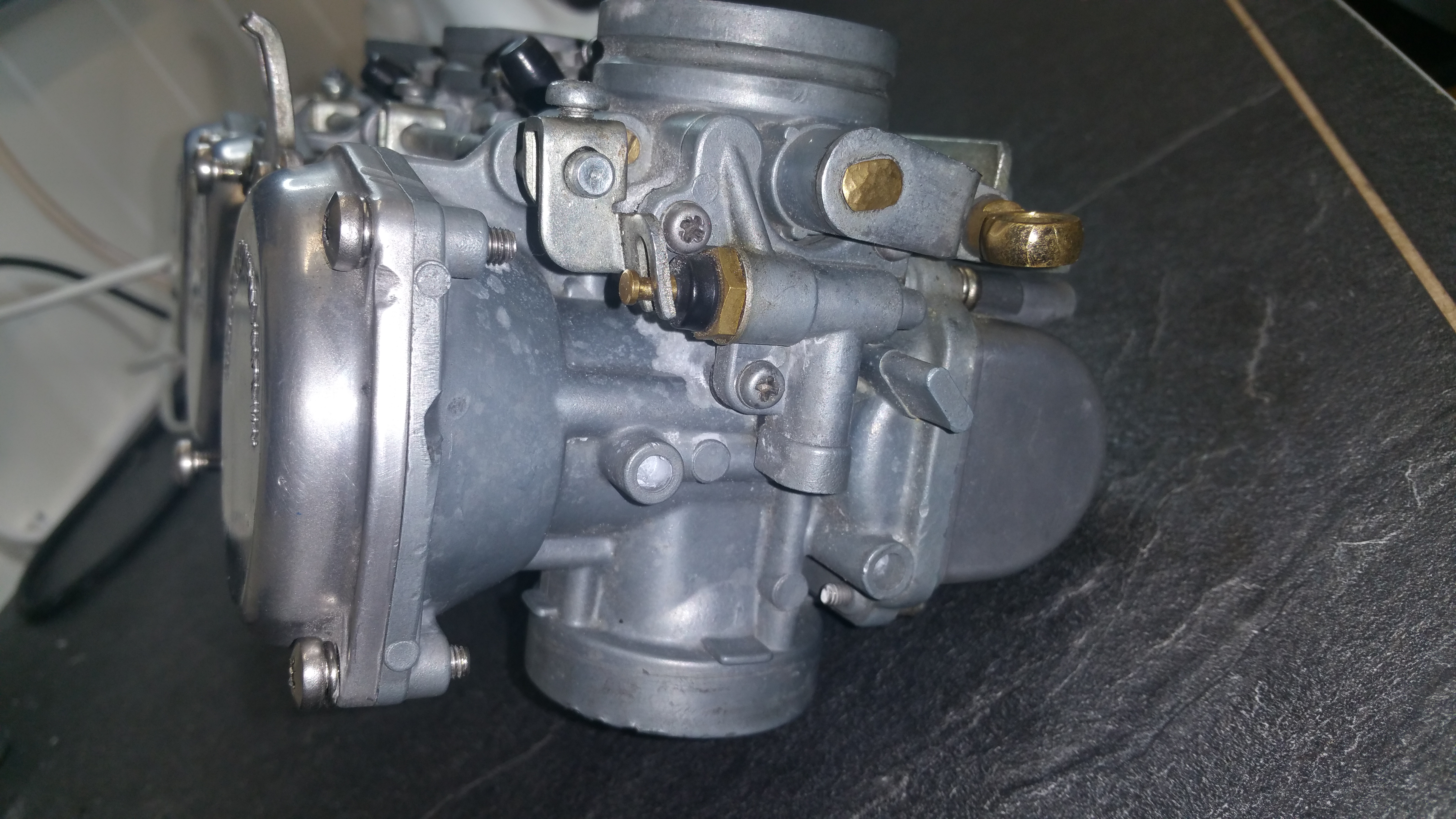
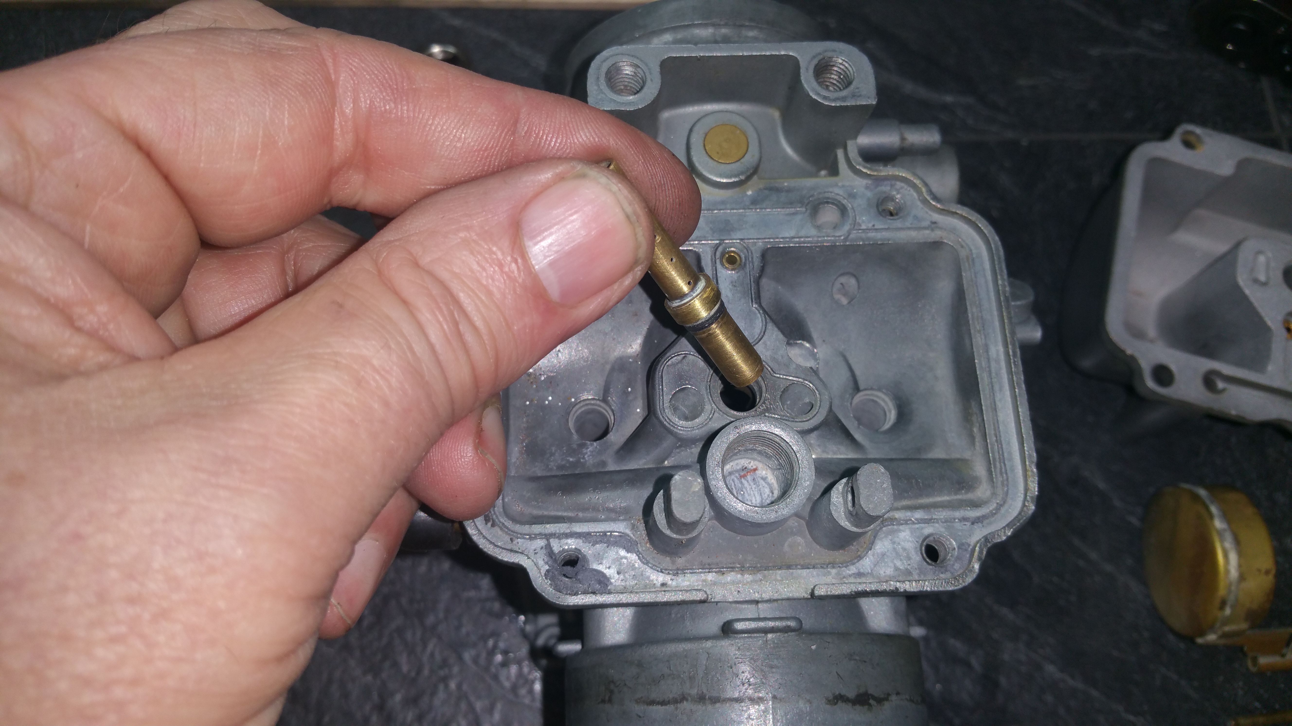
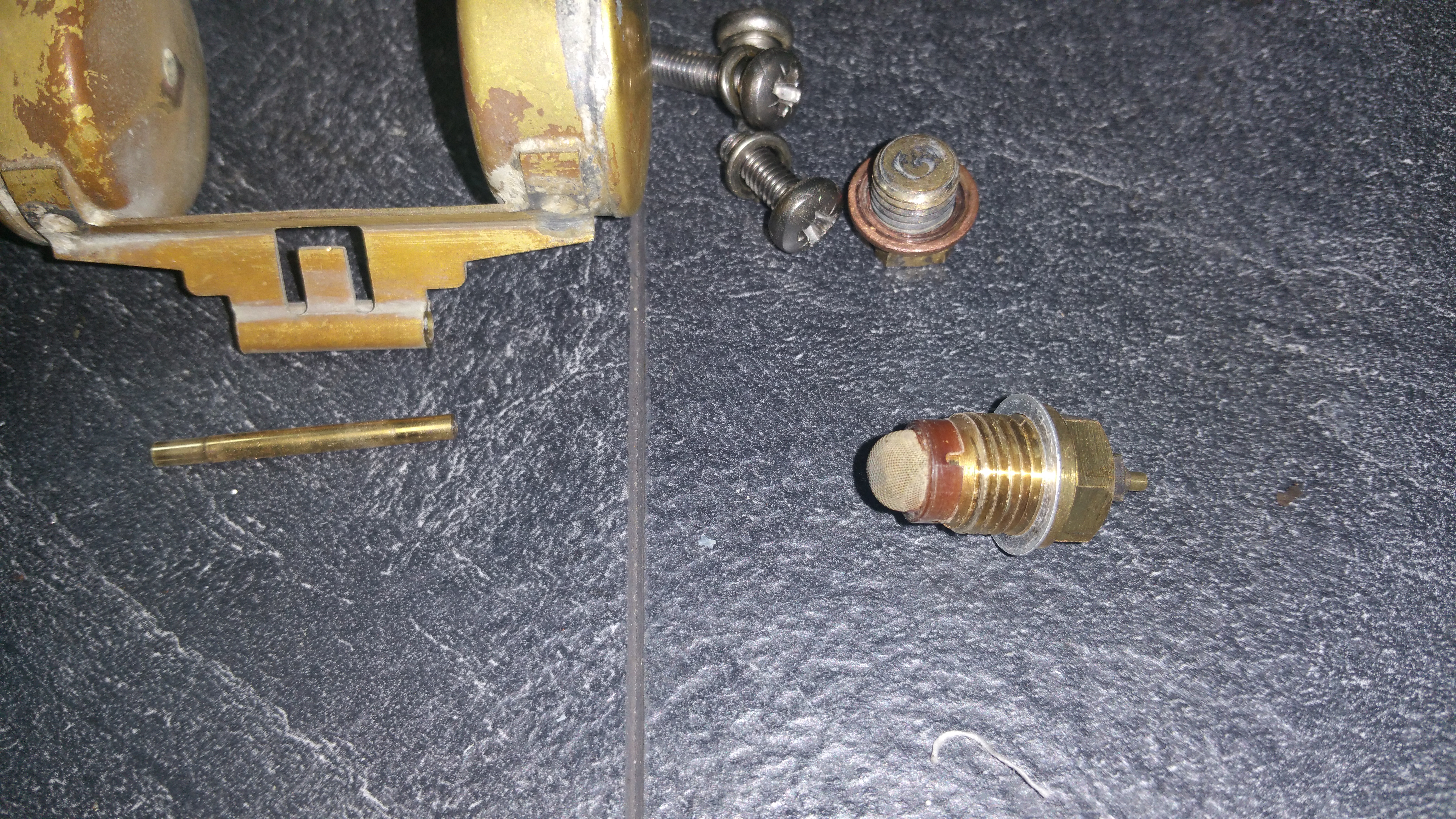
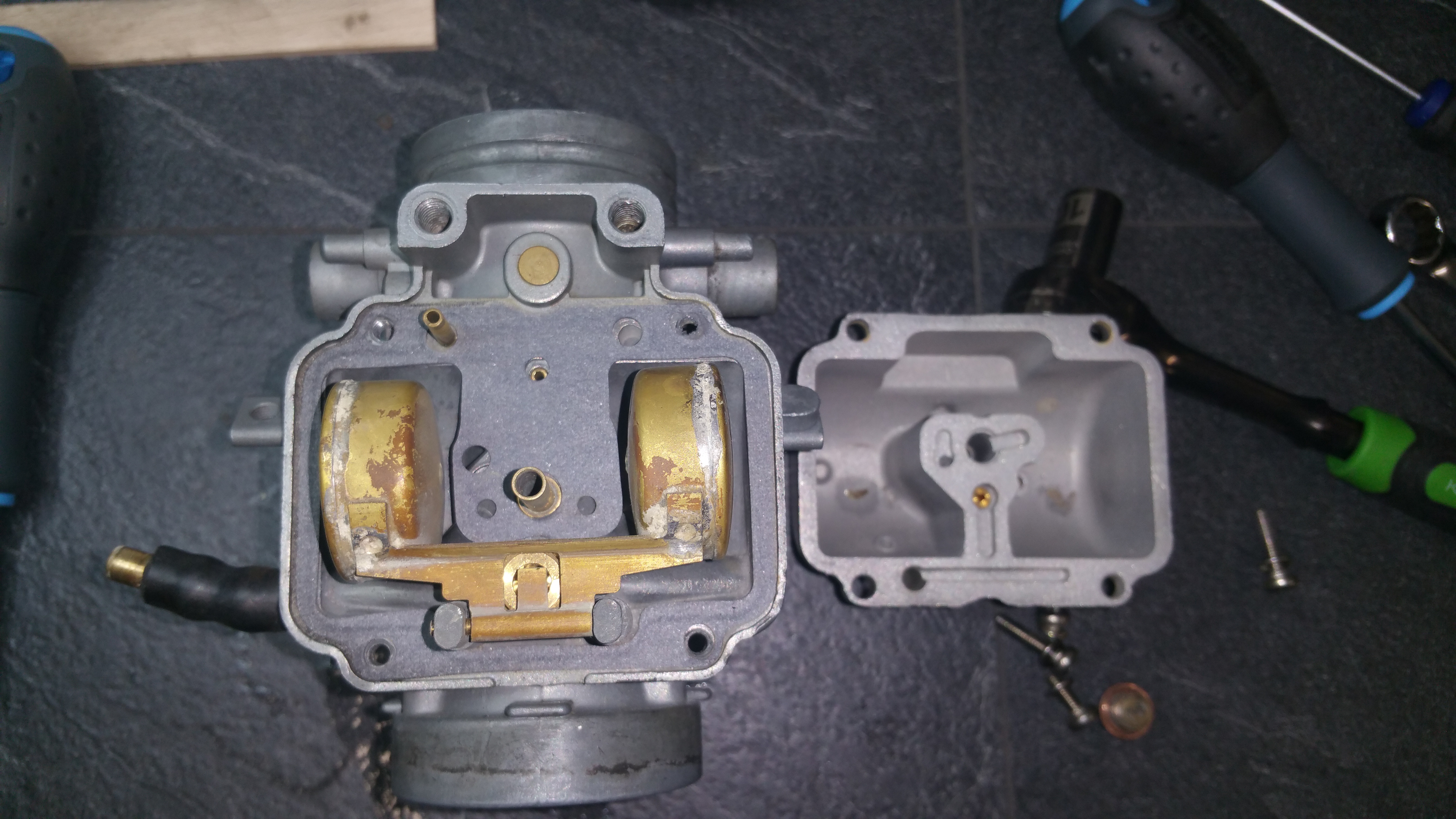
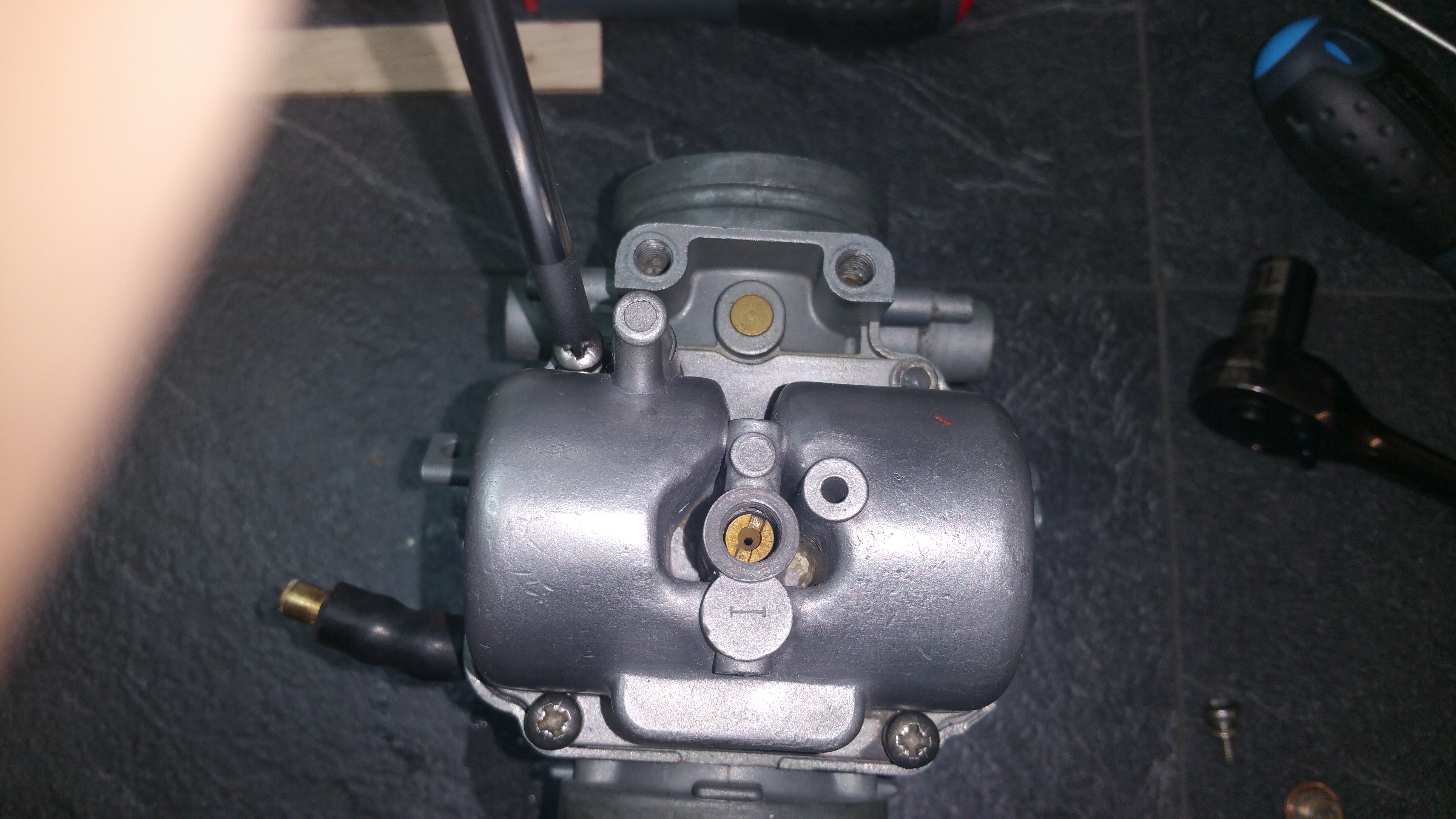
Disassembly:

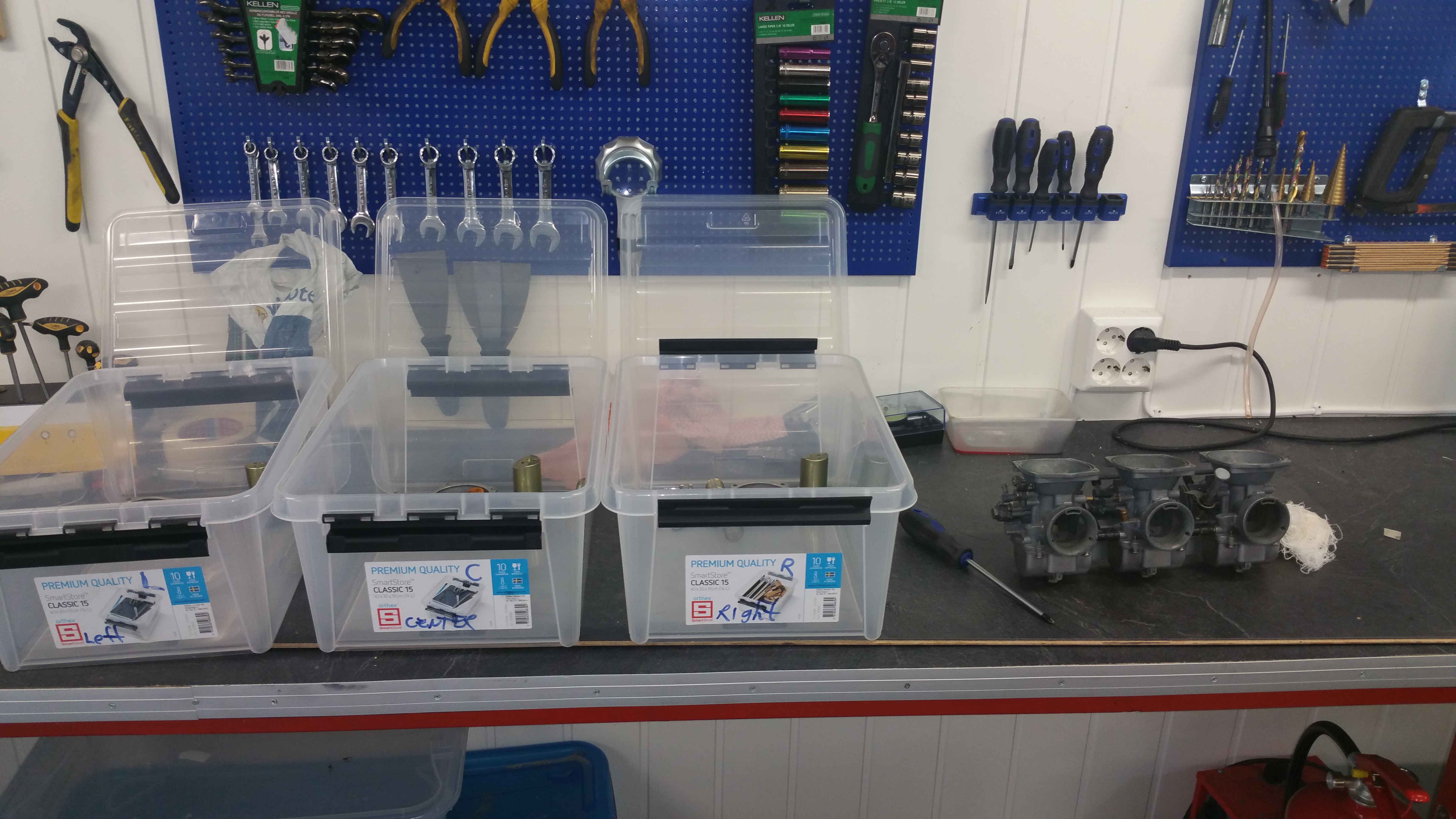
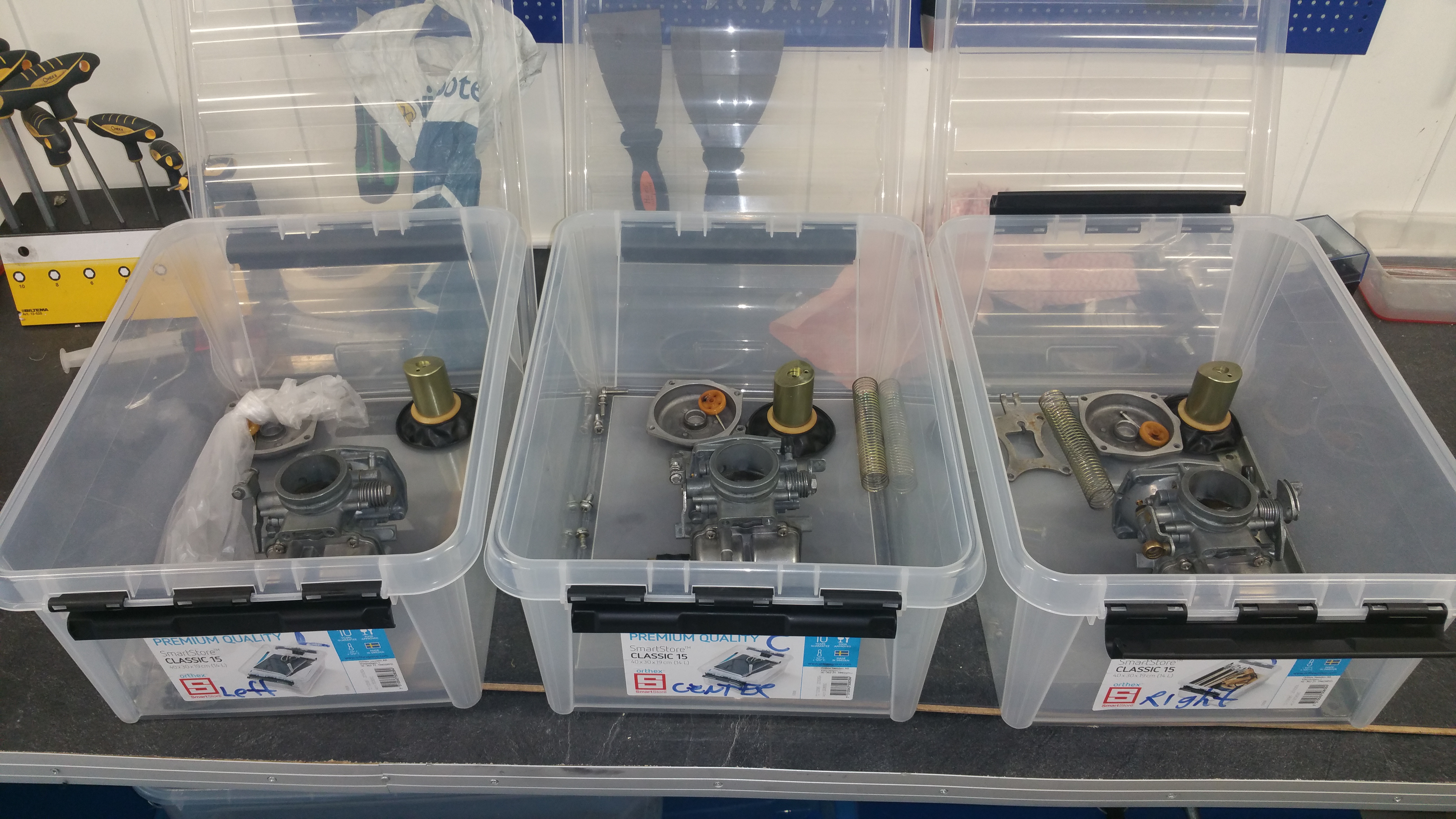
Important to organize the parts. Use boxes, plastic bags and label well to keep track of which parts belongs to the Left, Center and Right carburetor.
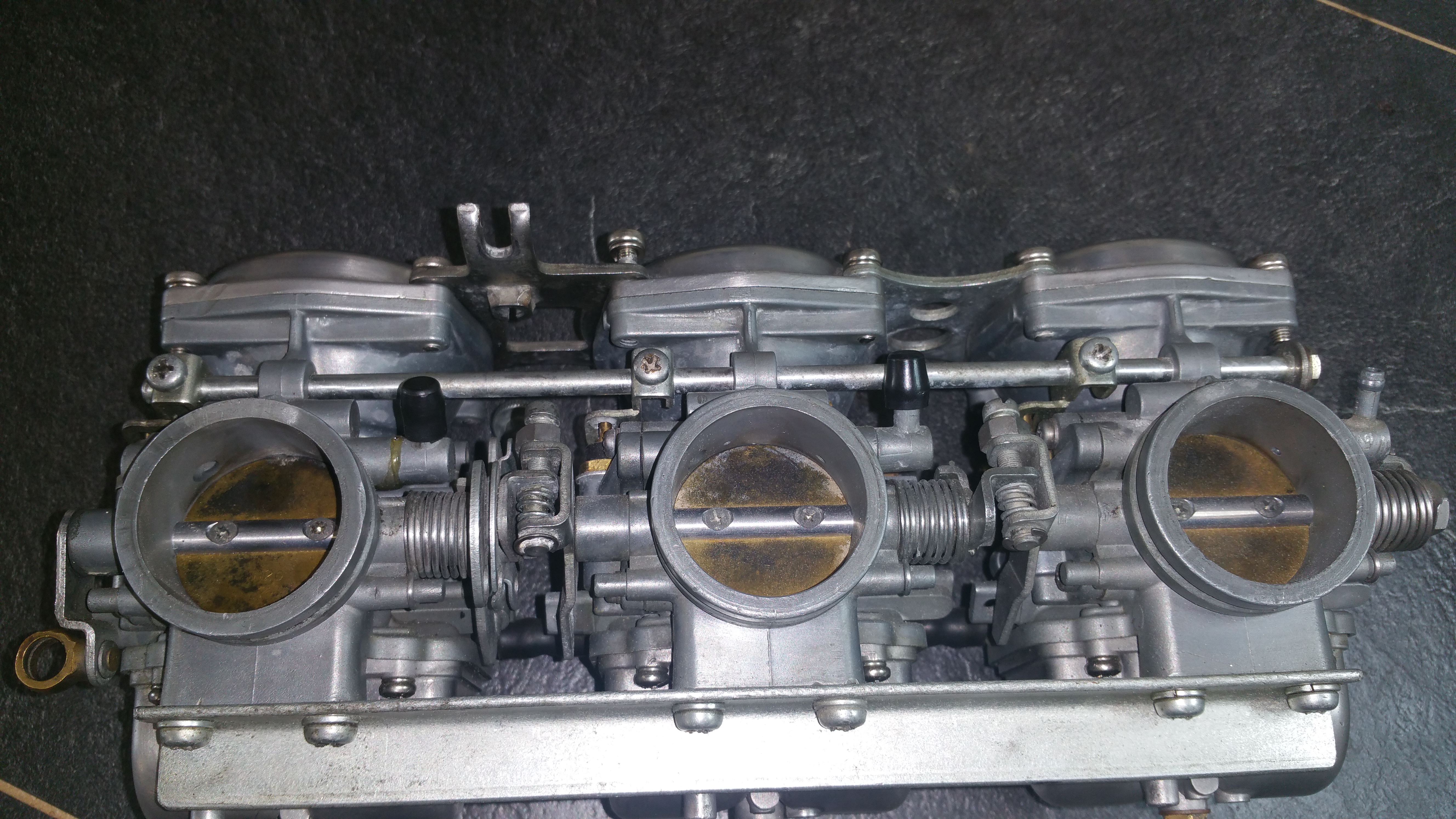
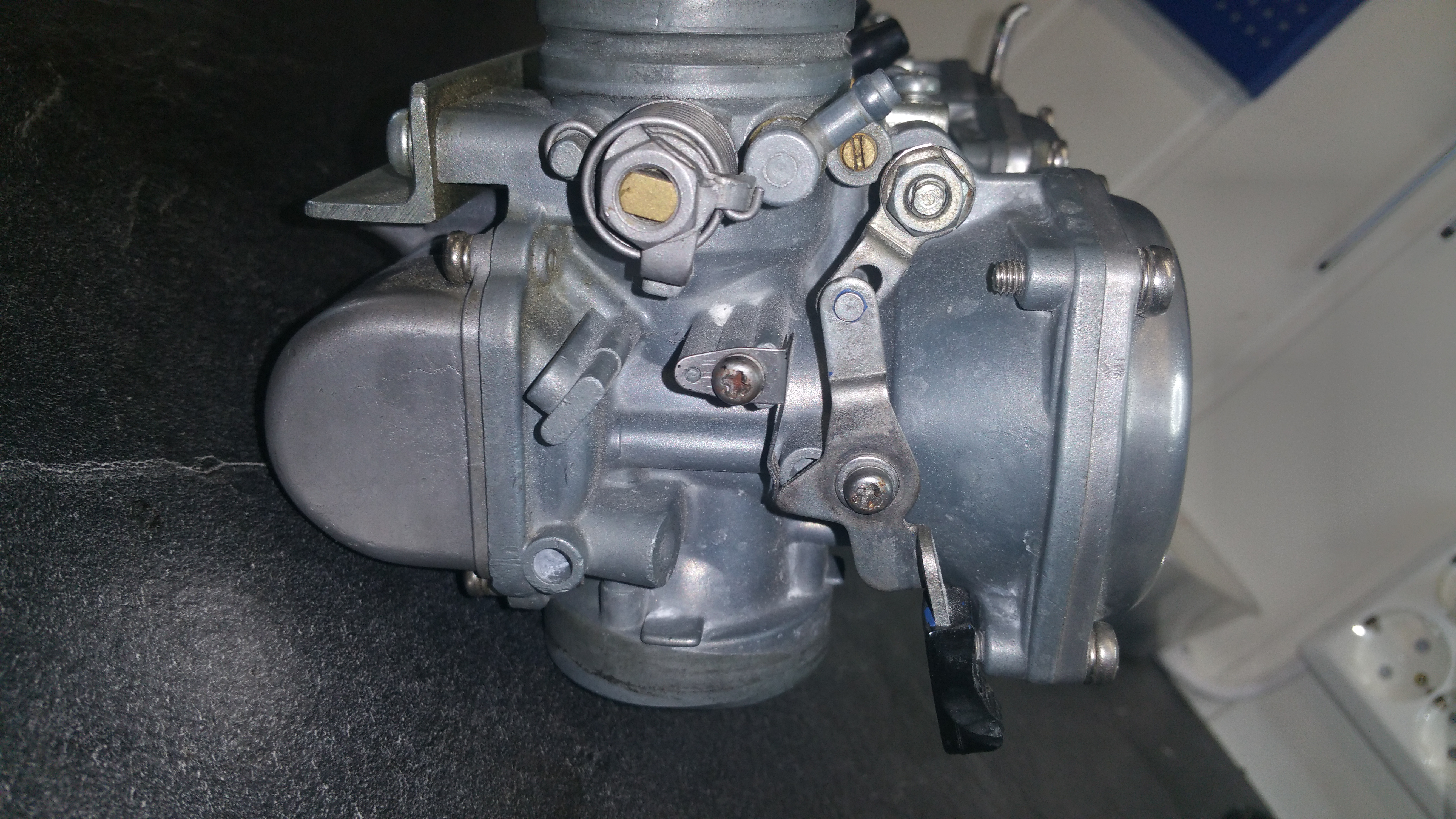
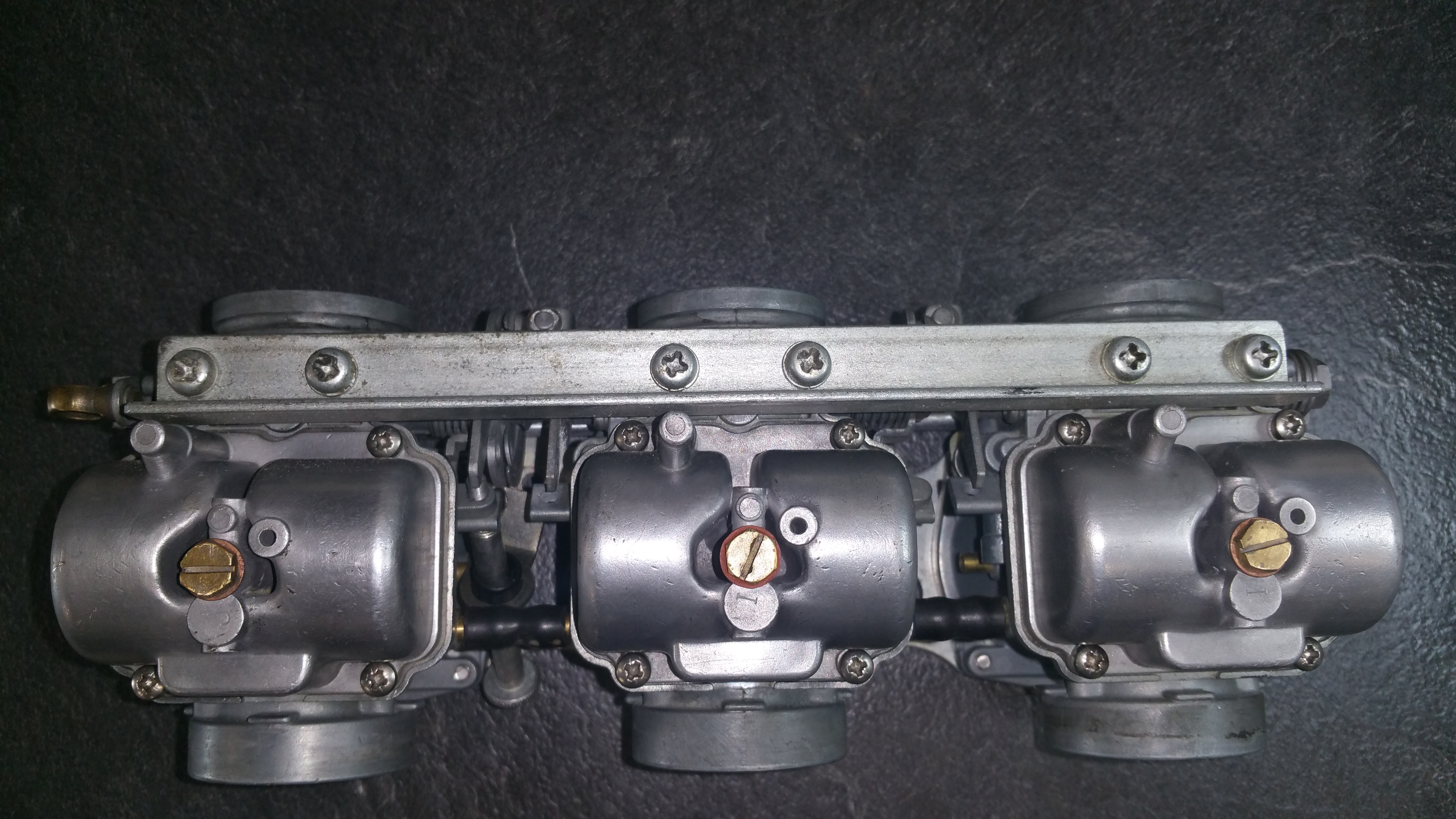
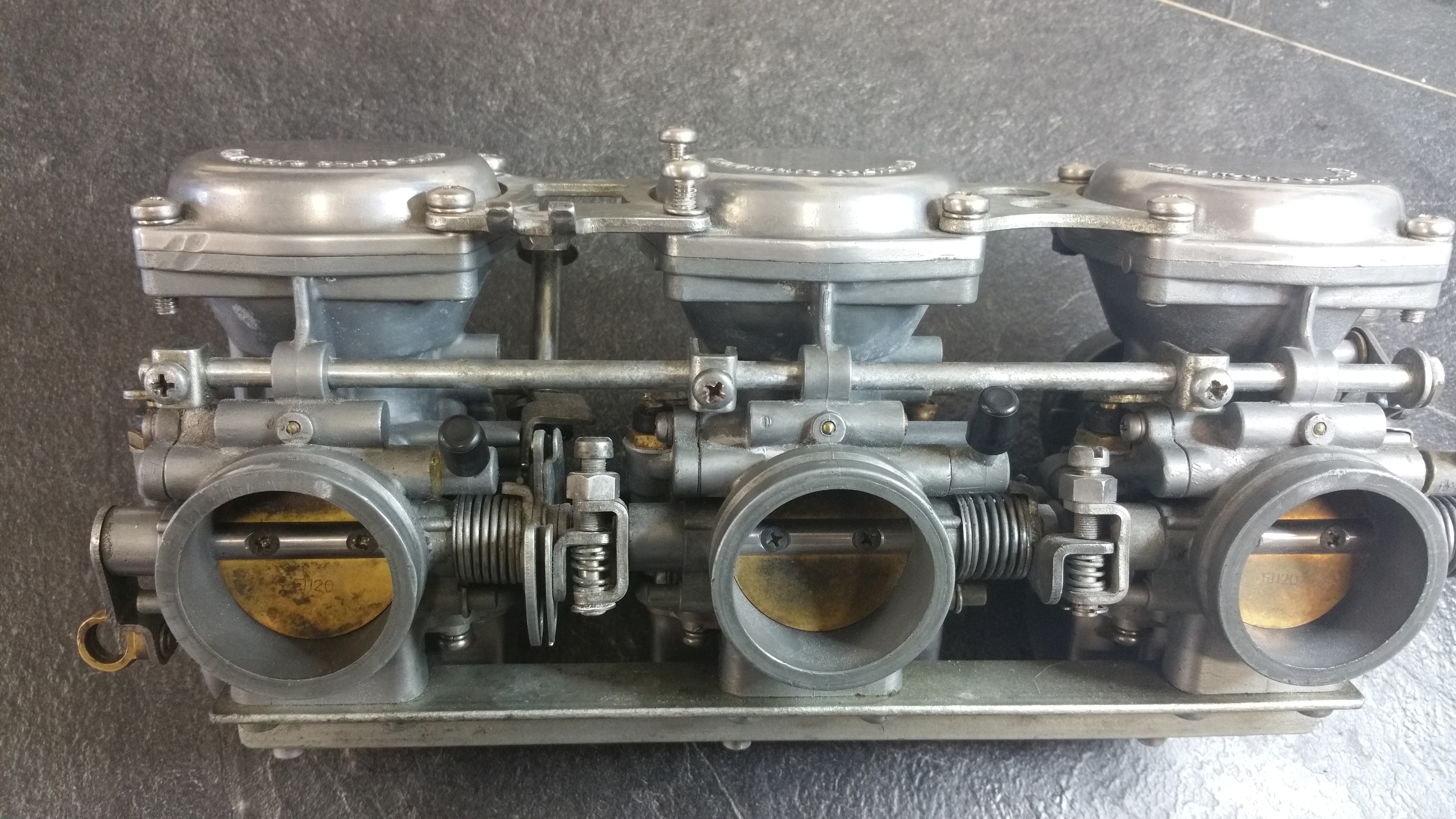
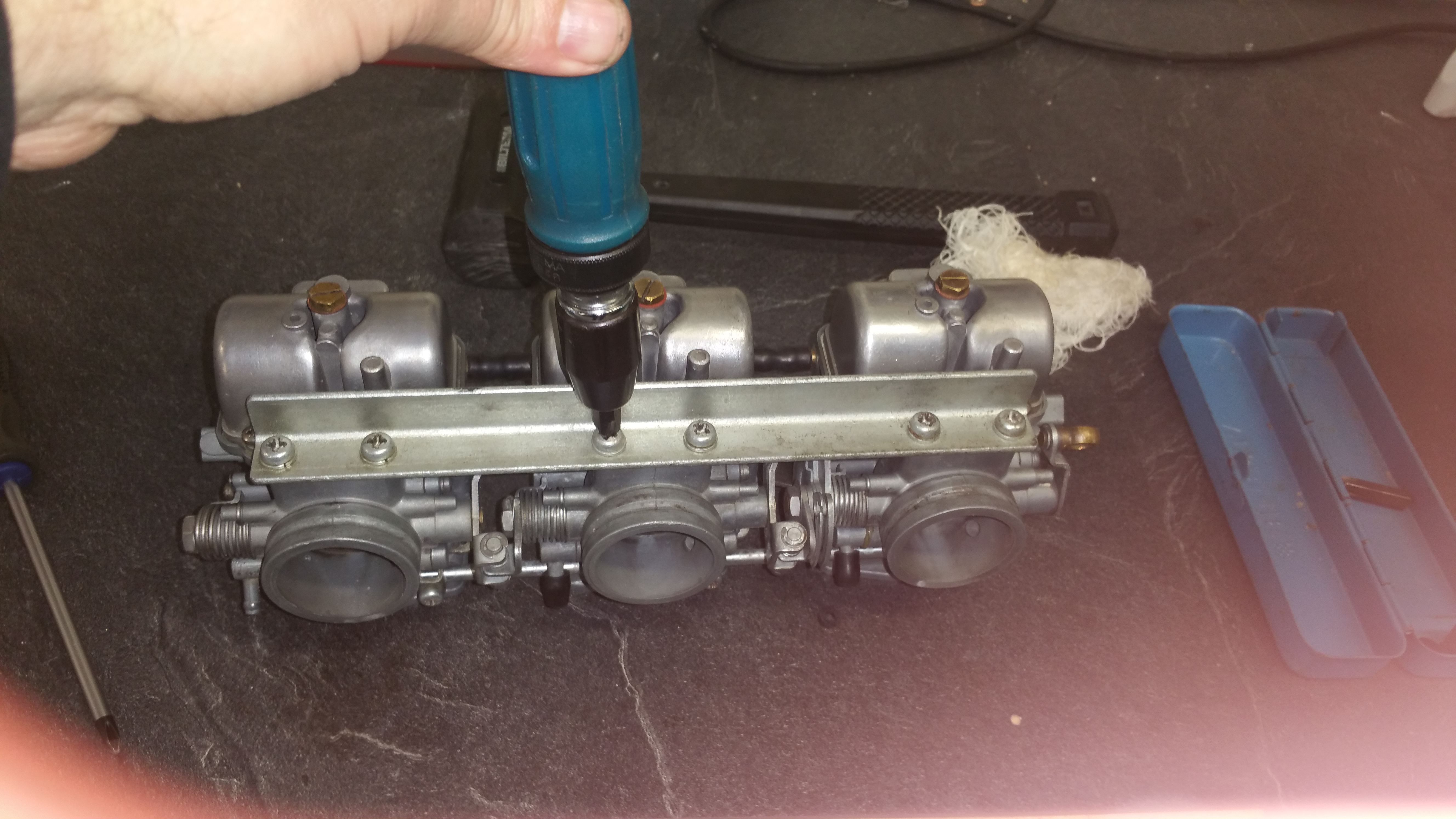
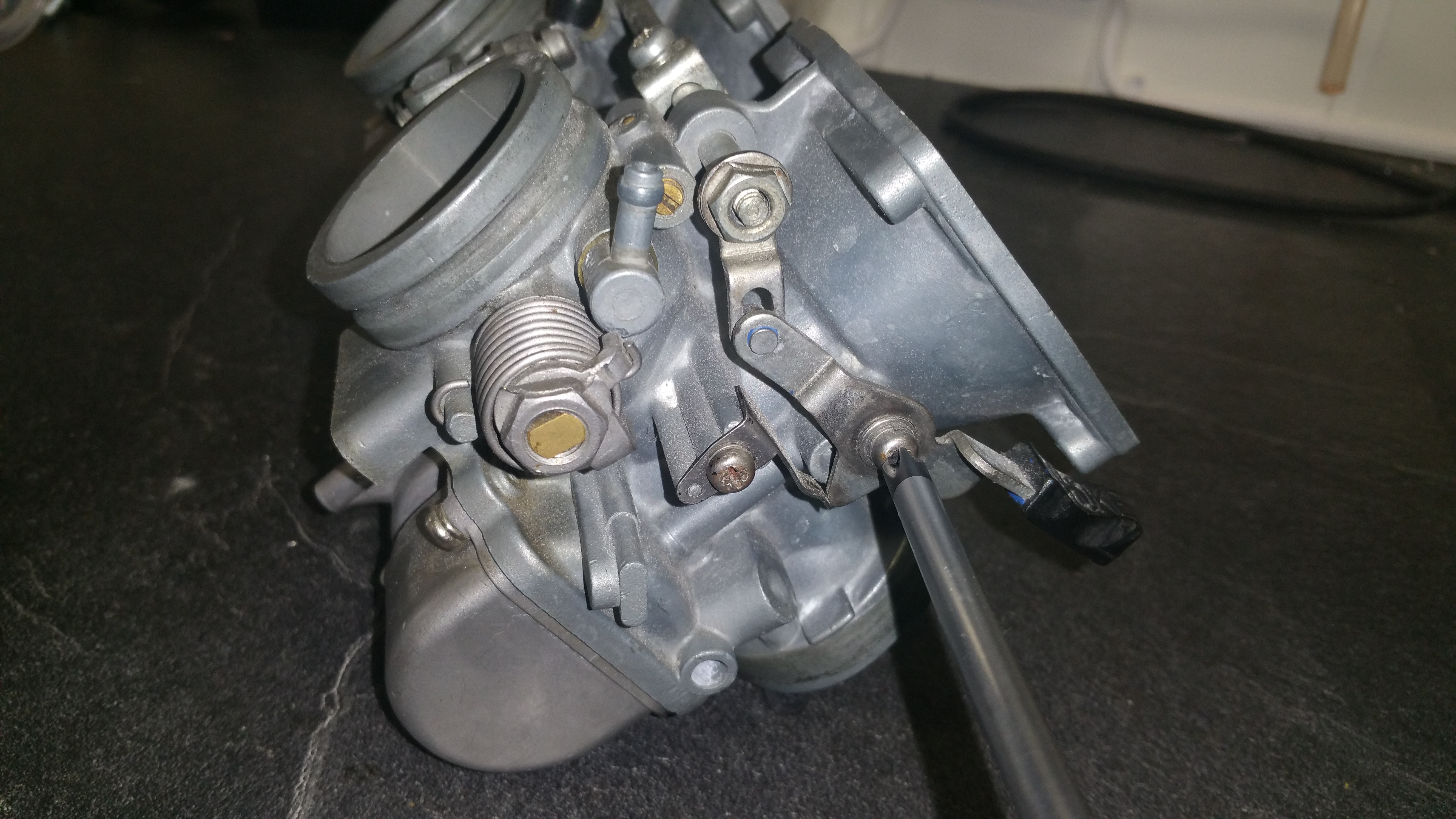
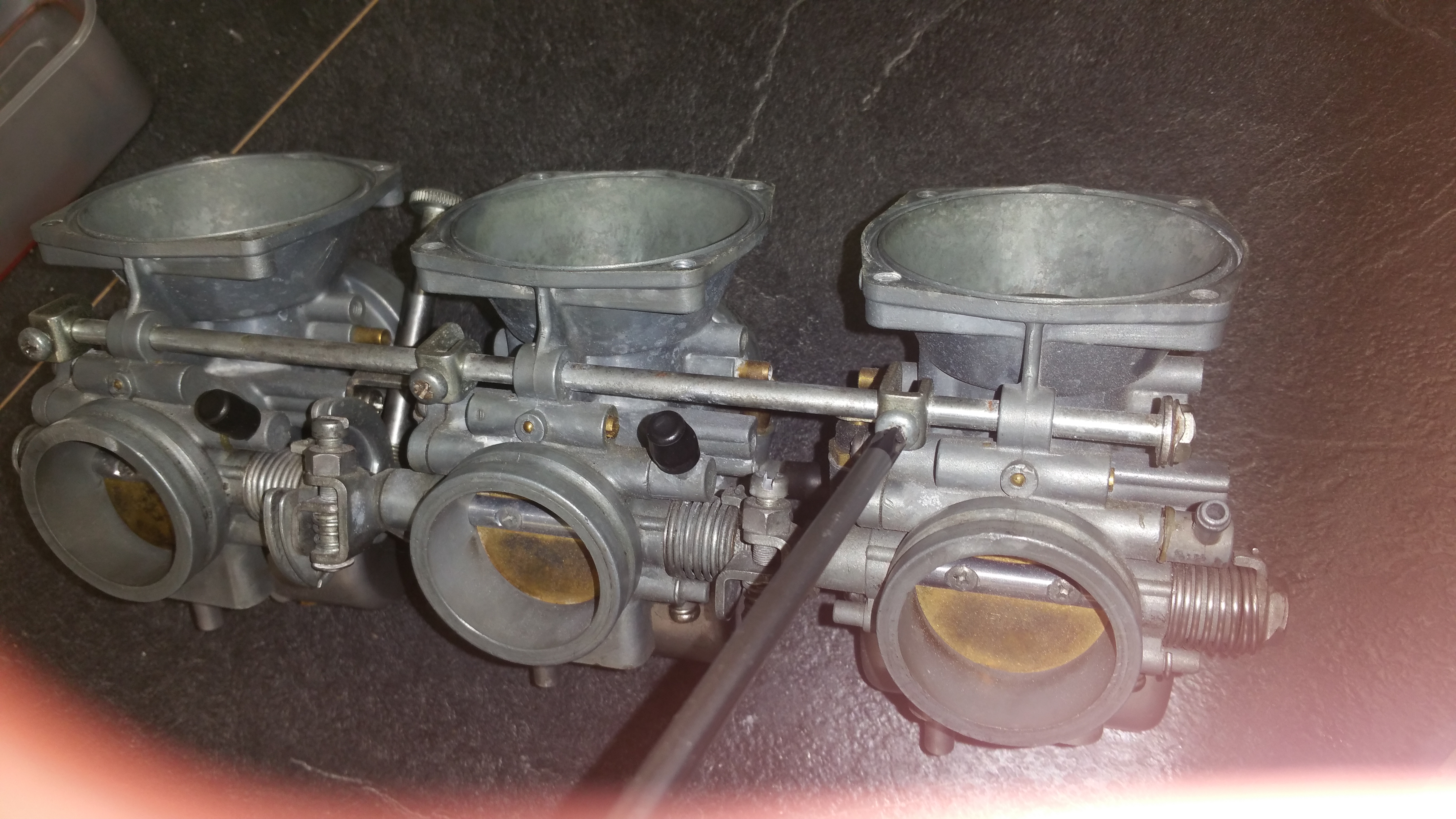
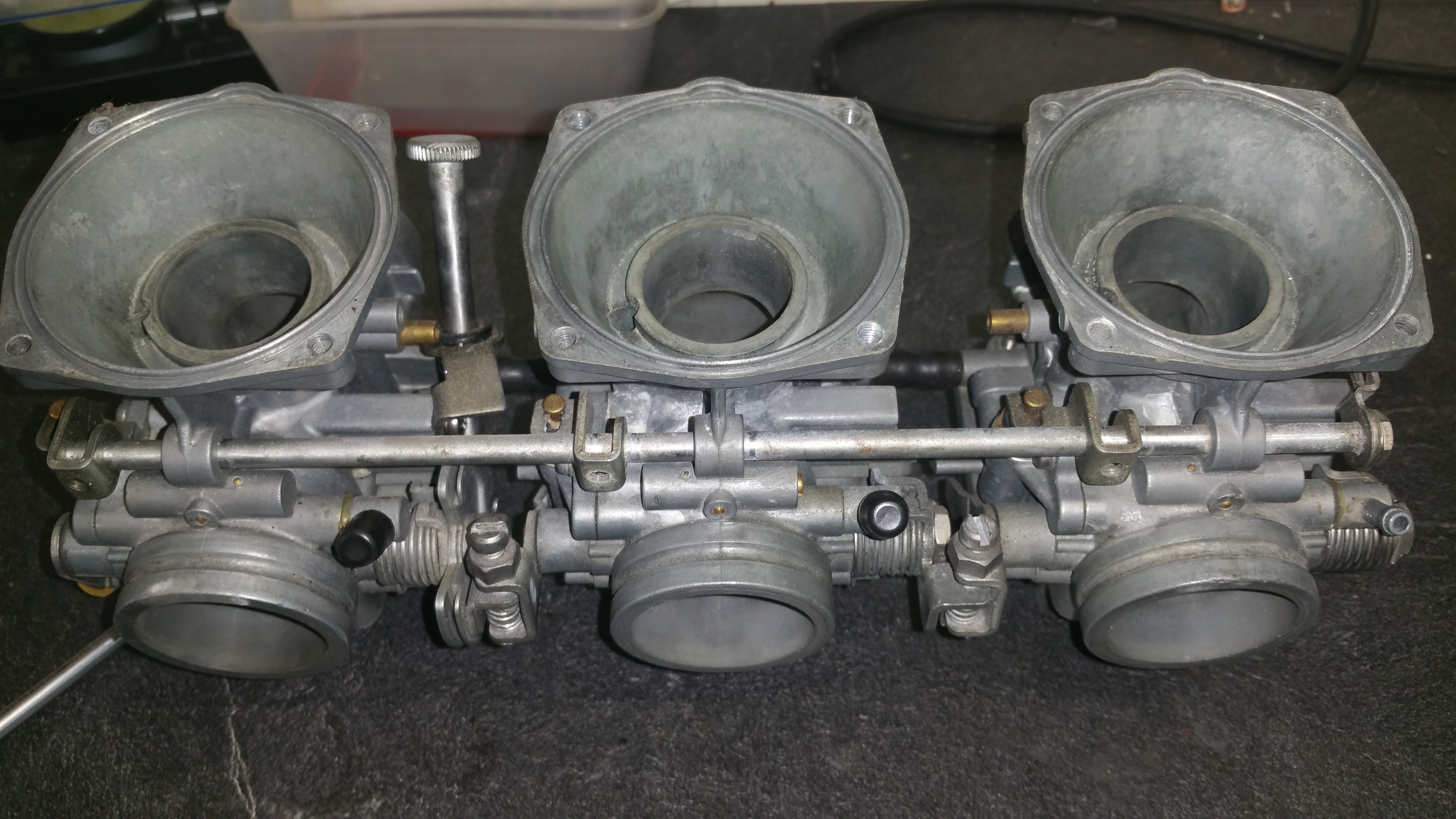
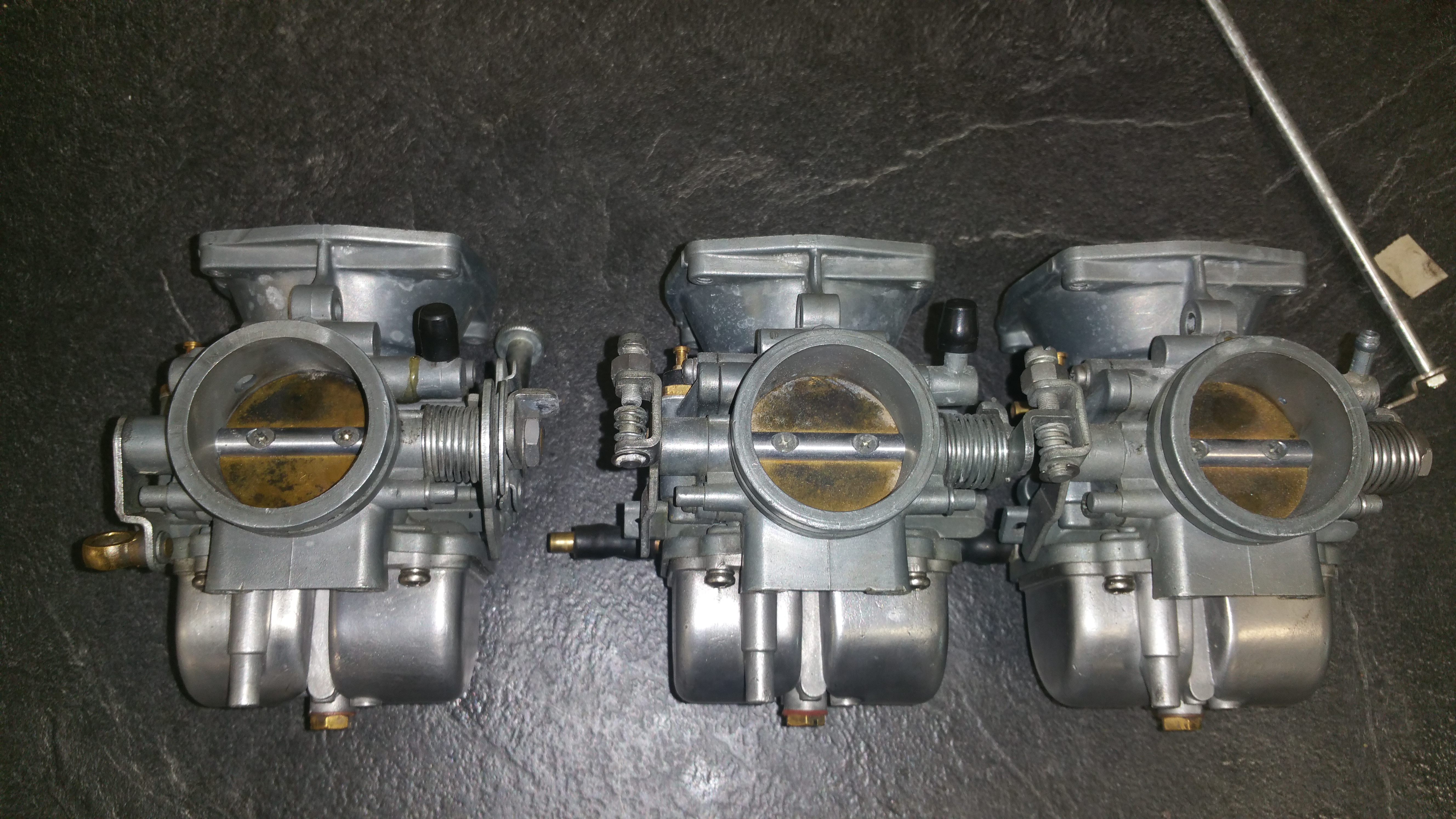
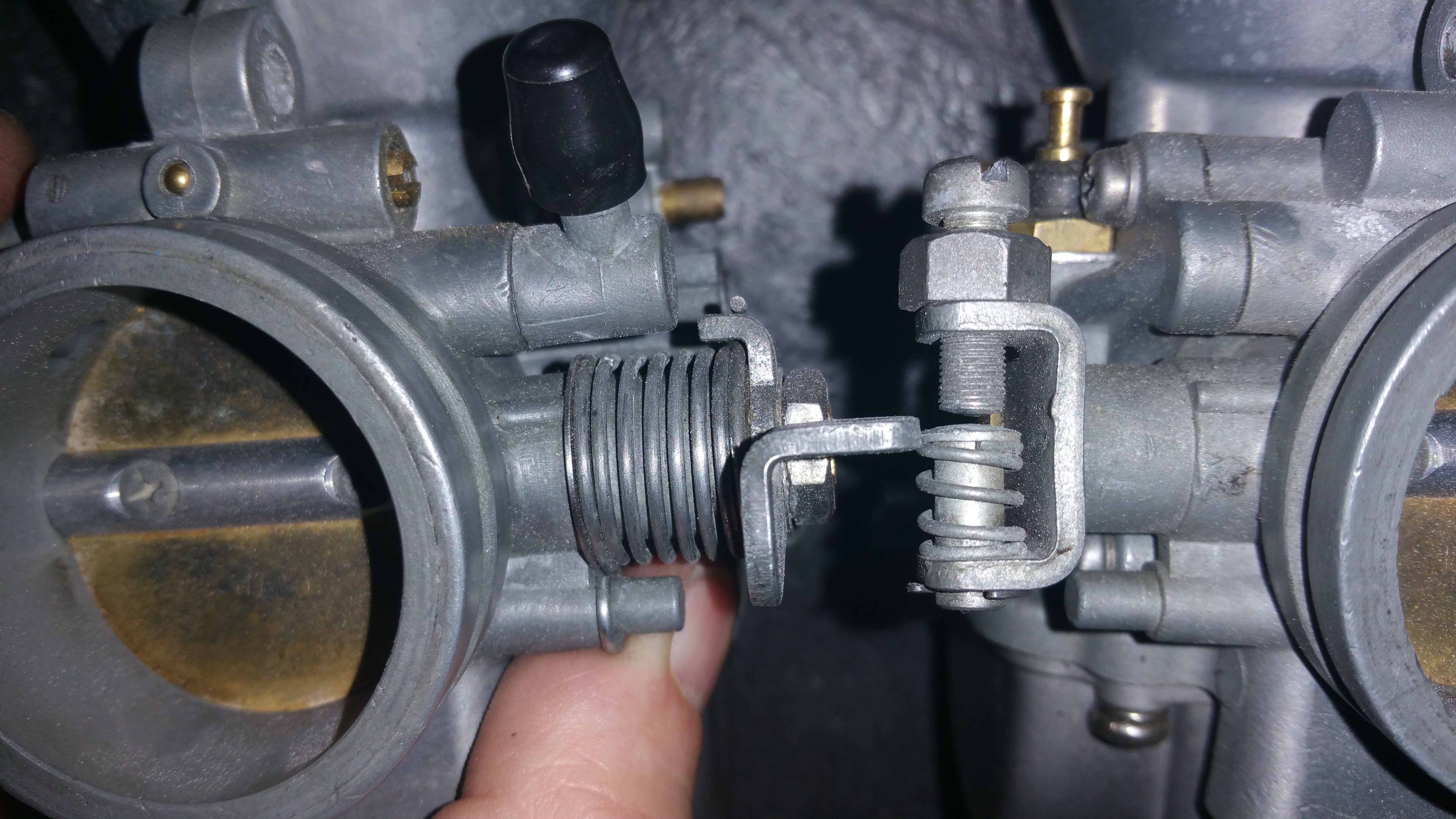
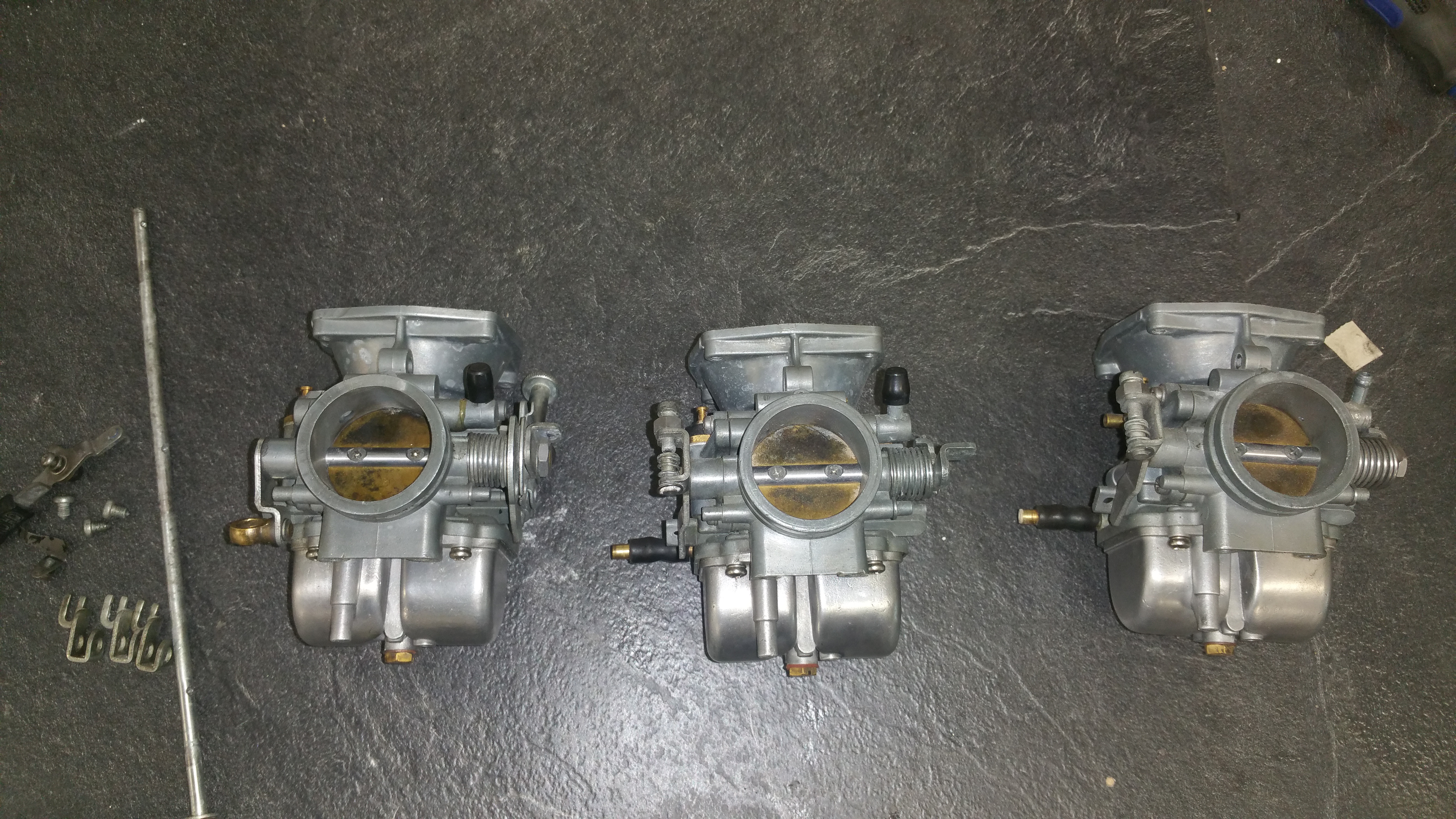
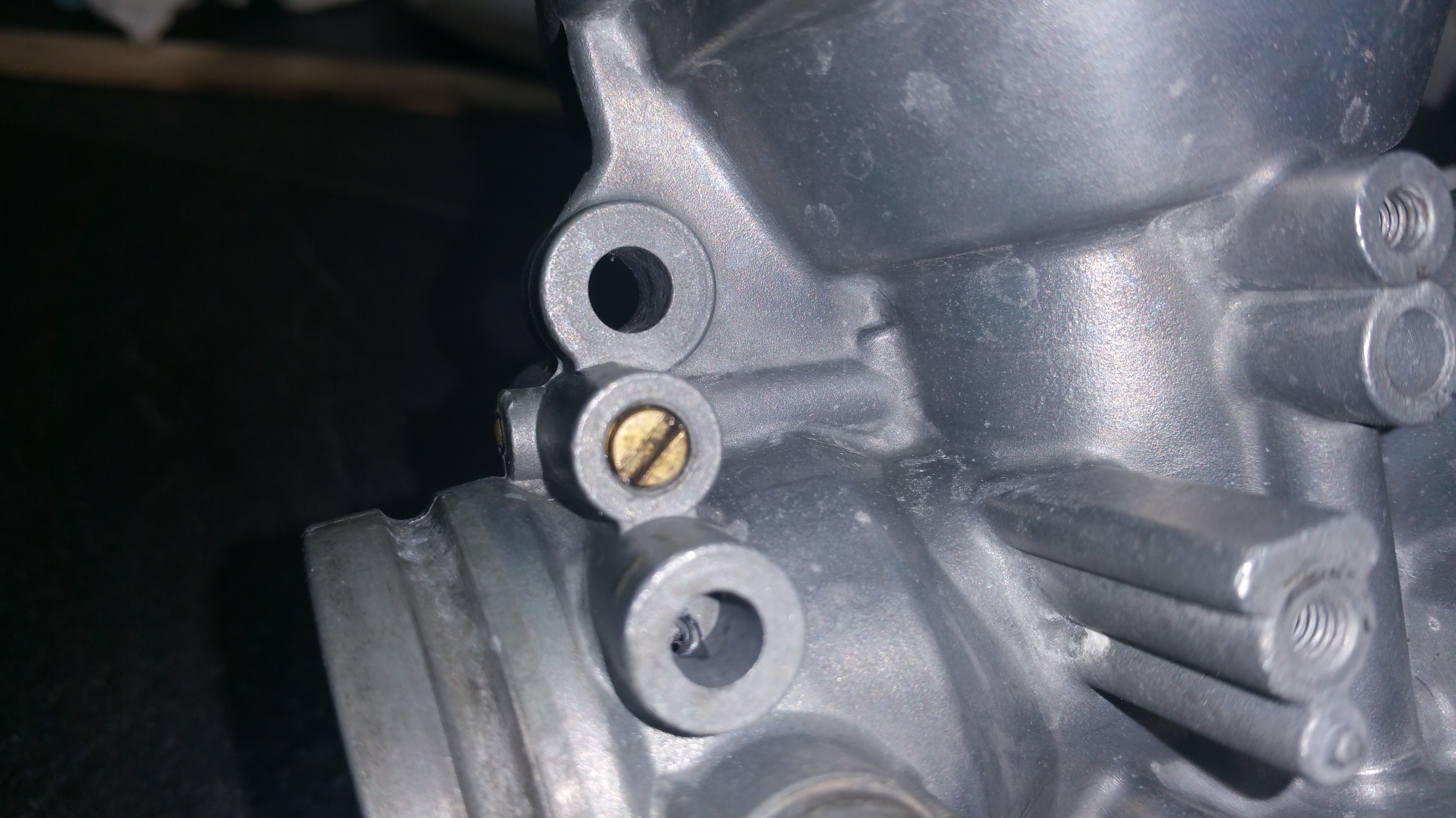
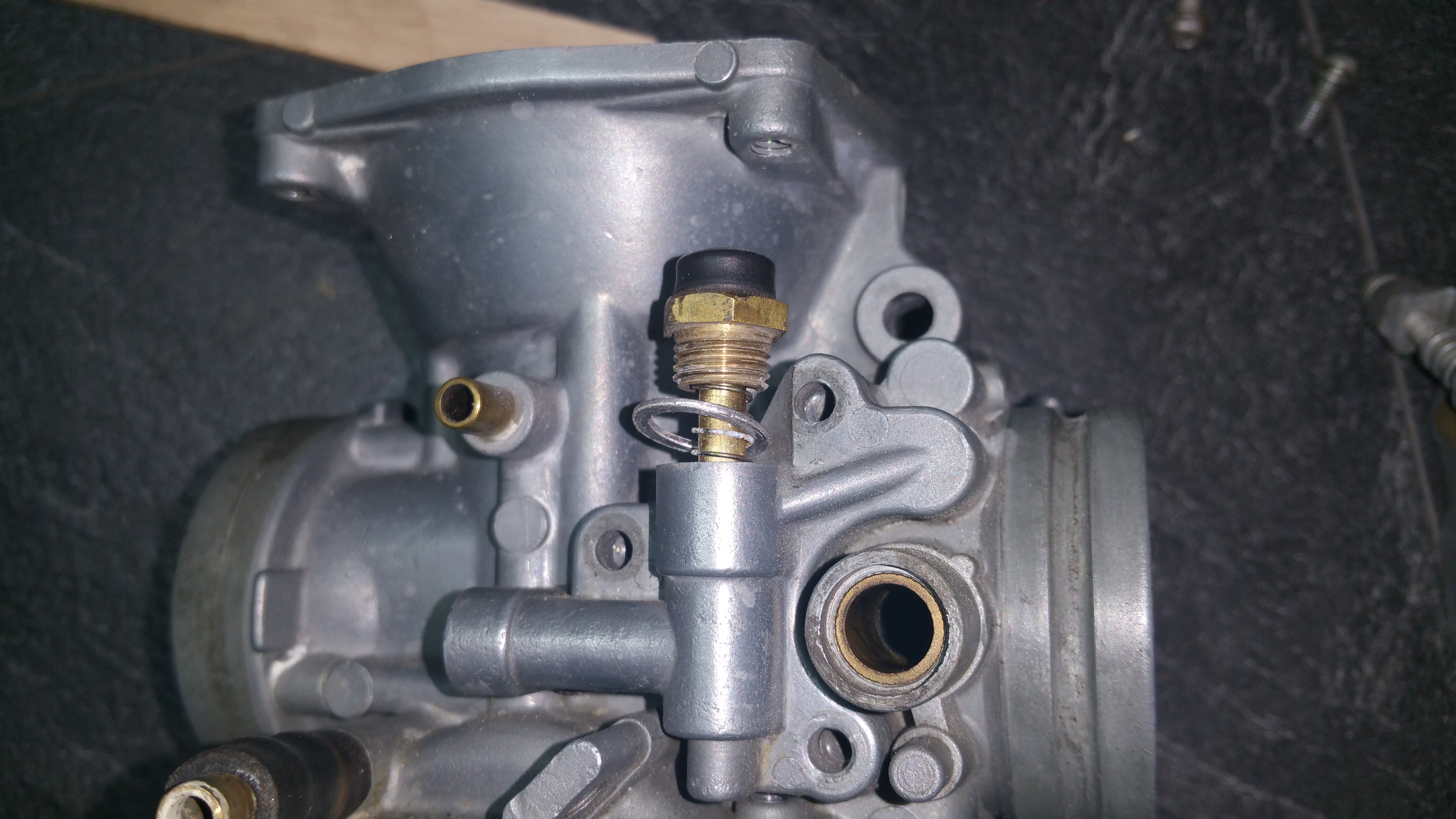
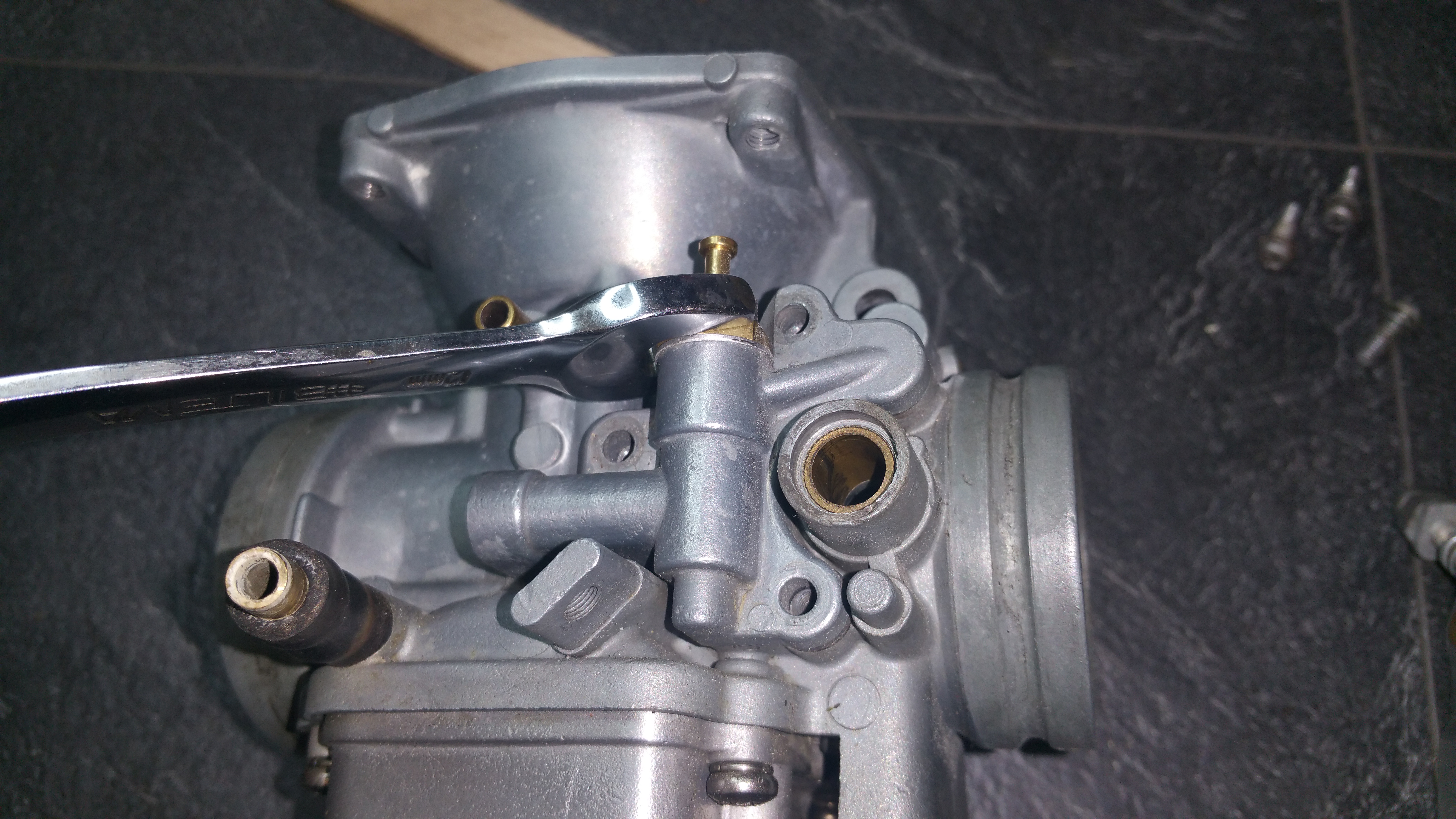
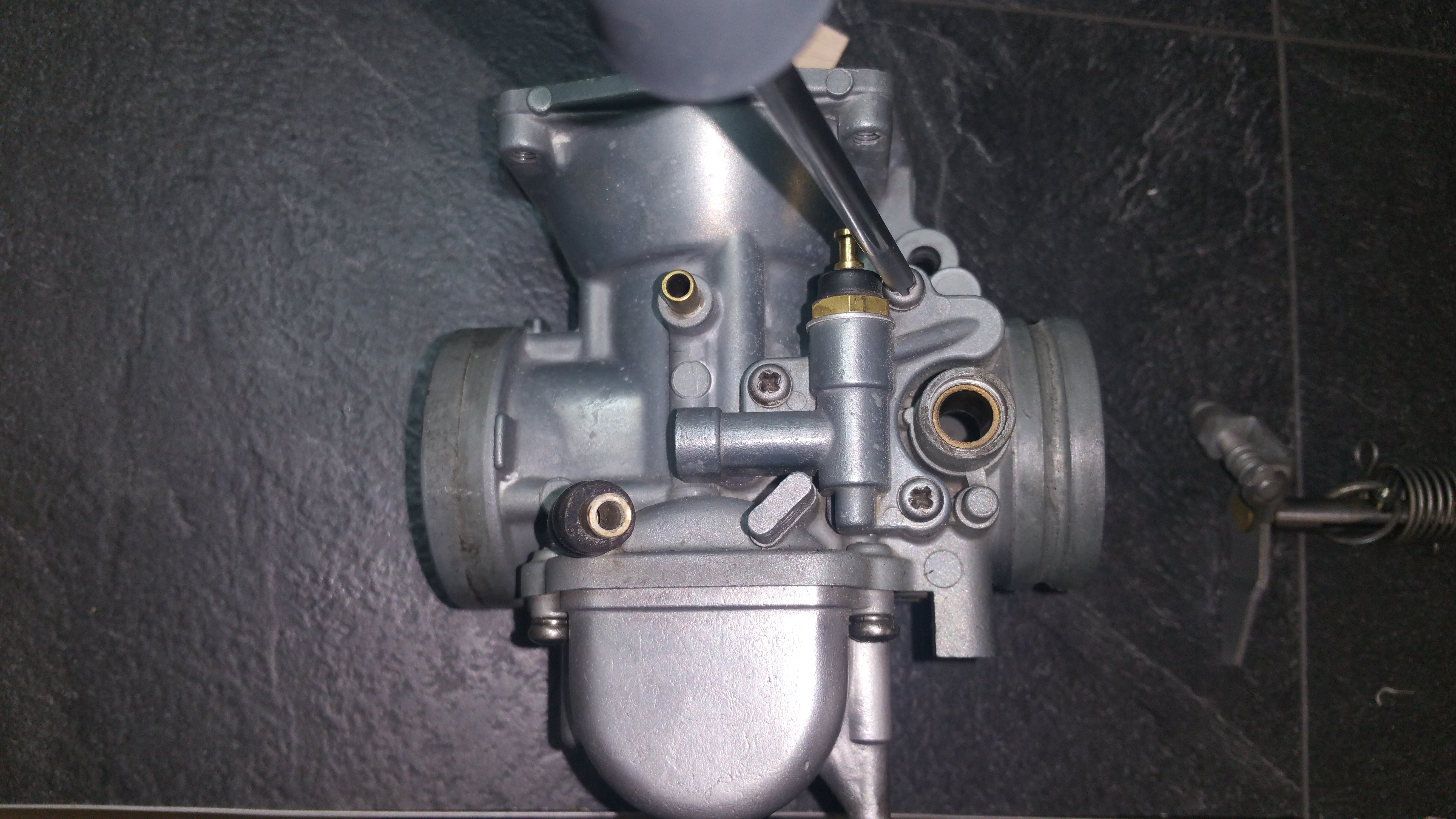
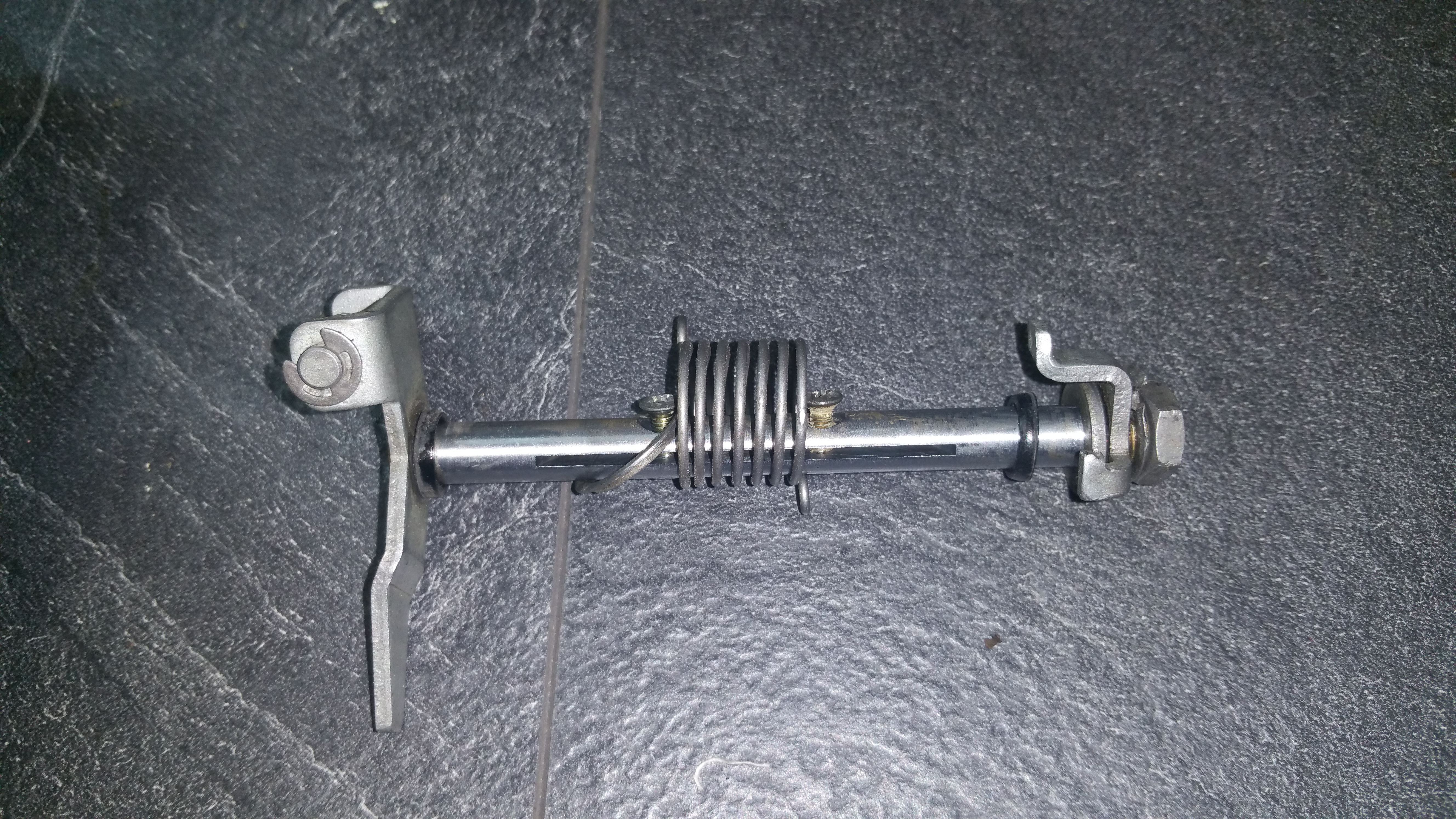
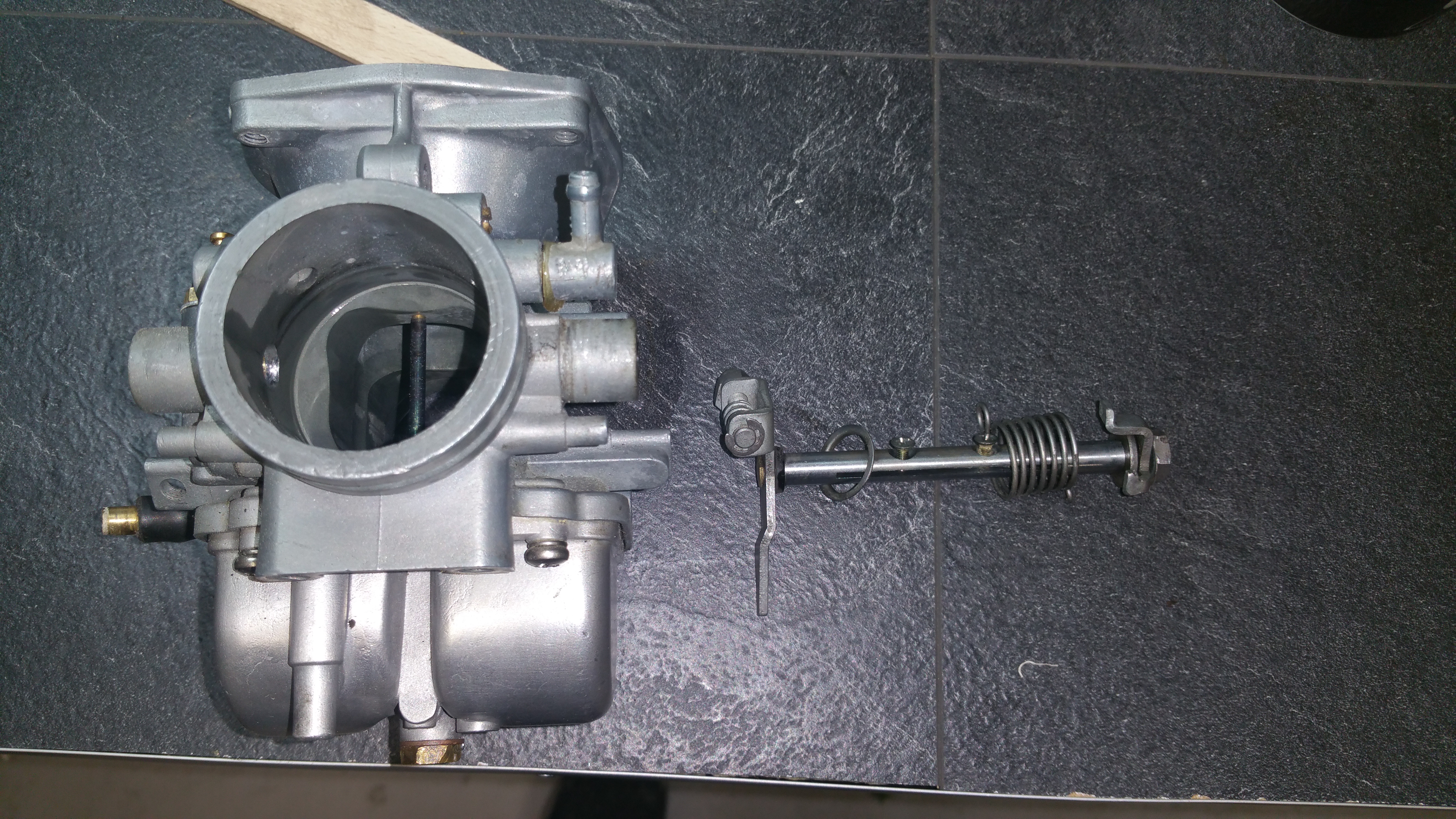
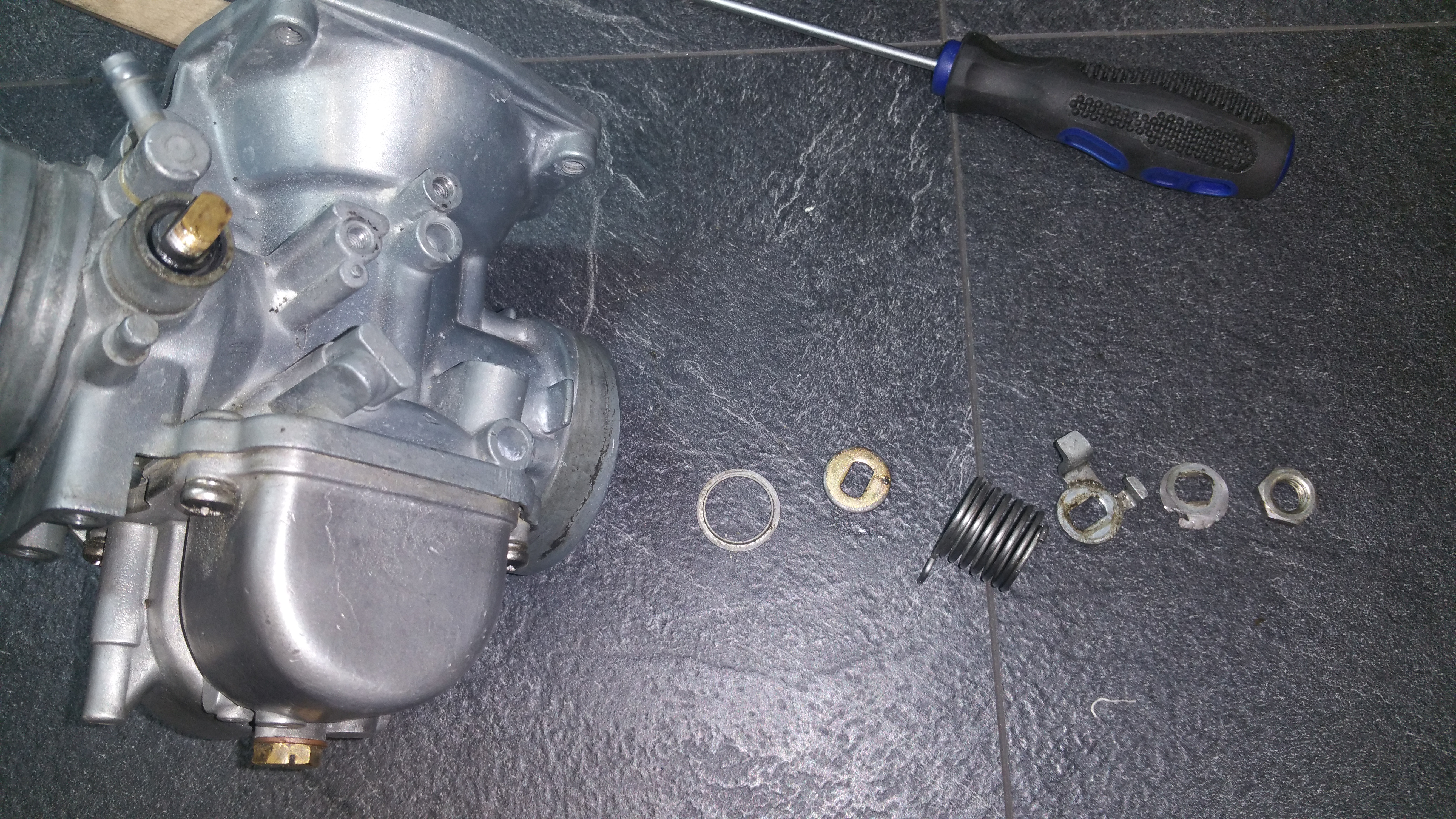
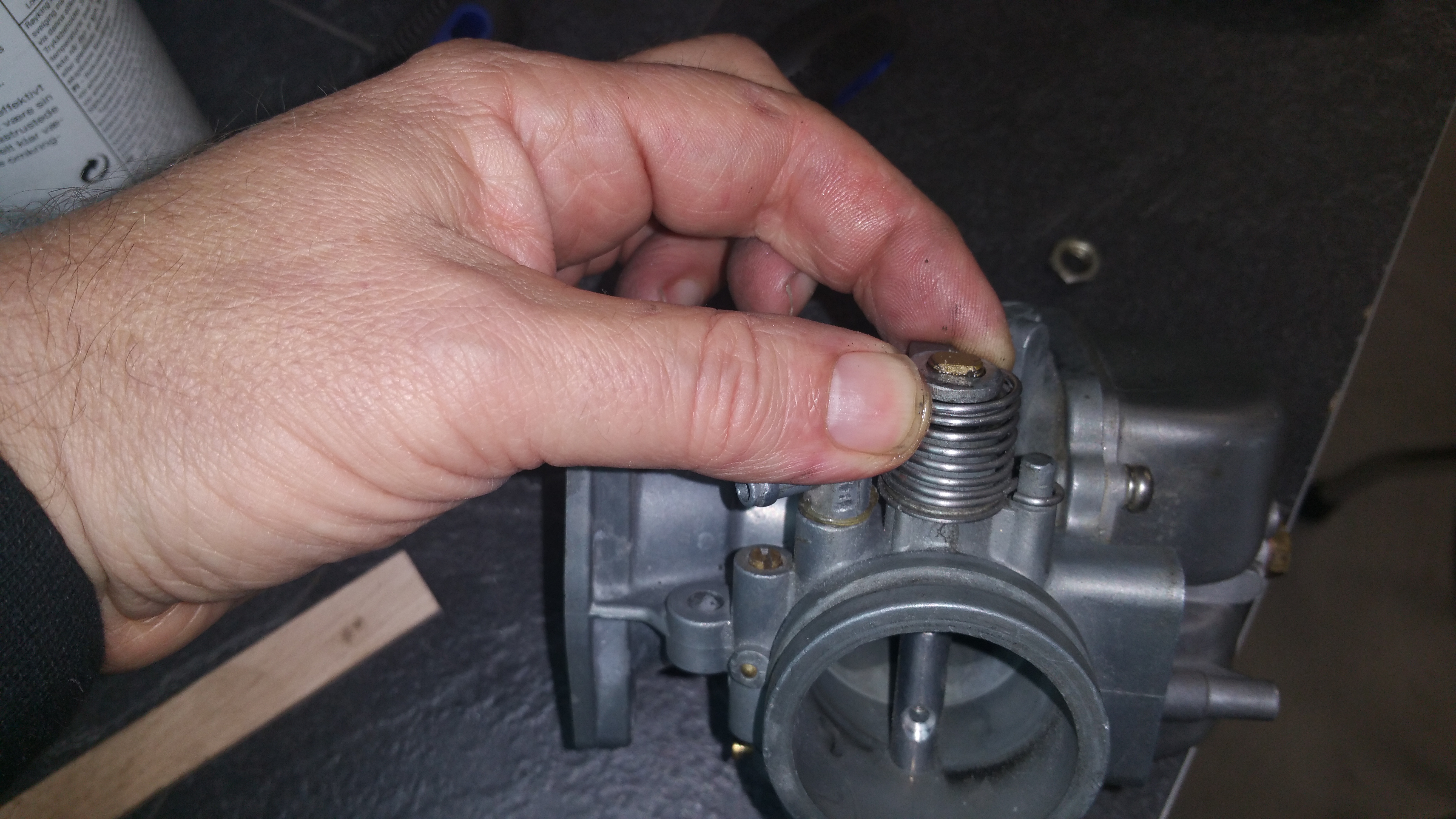
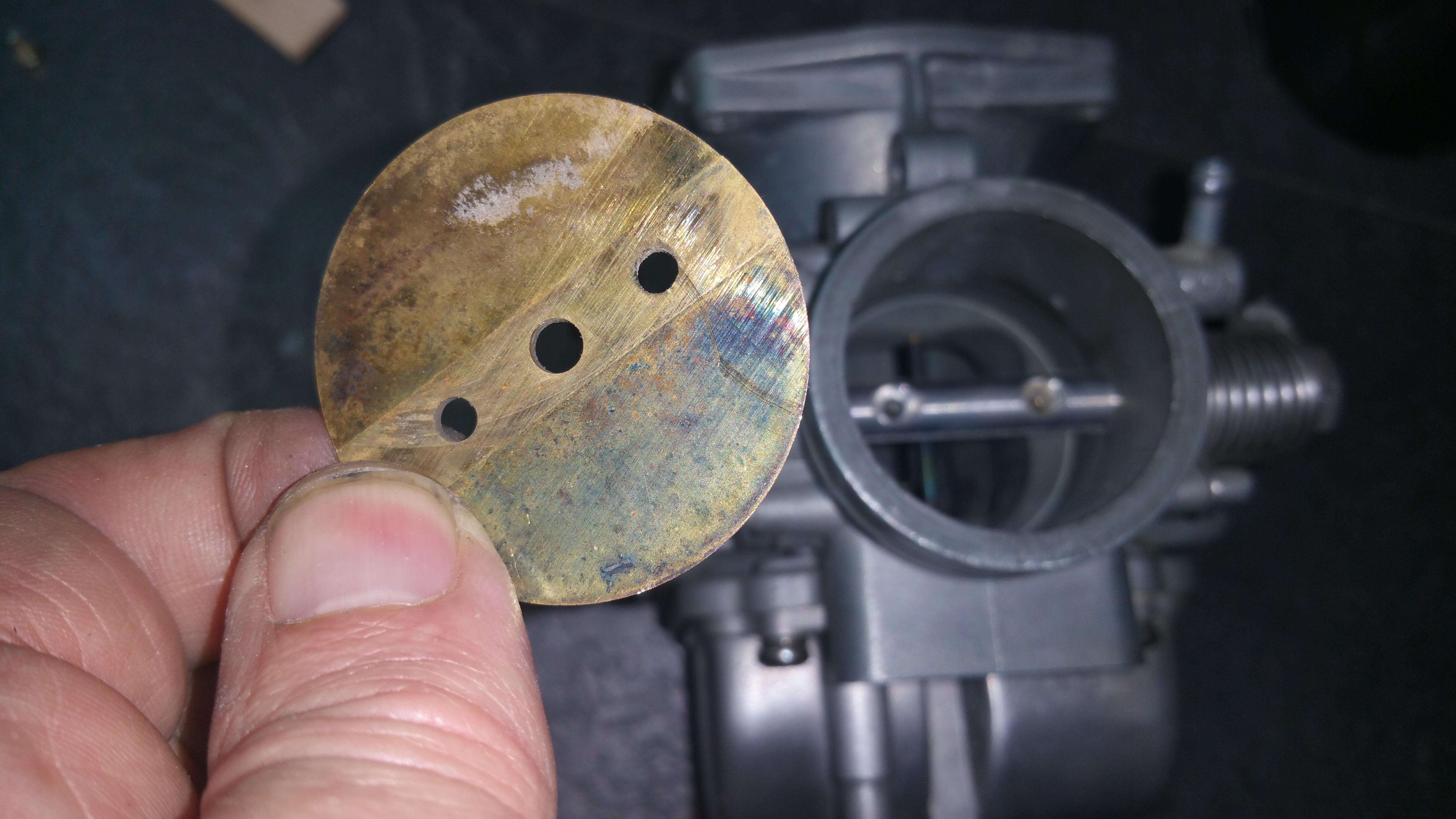
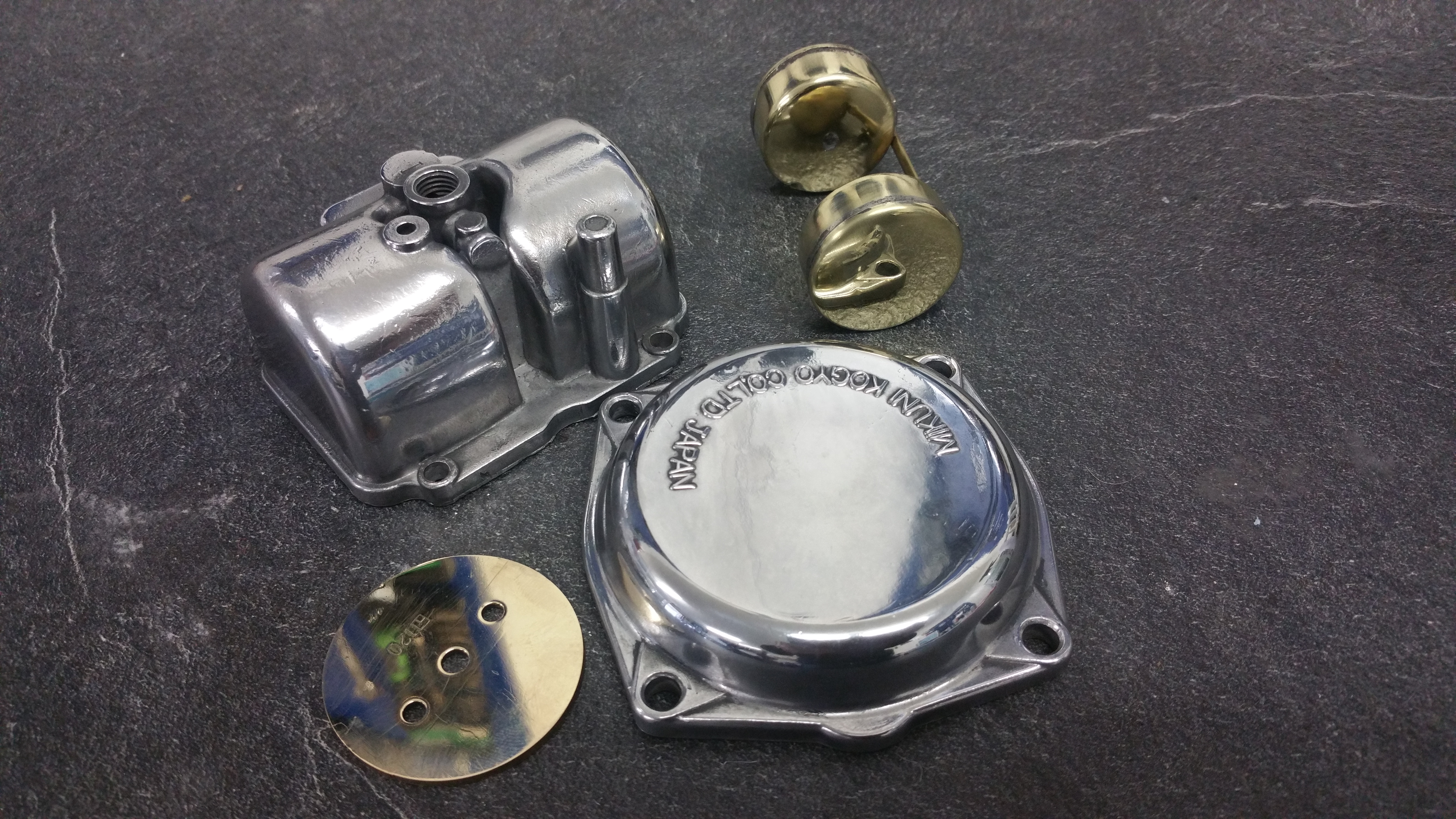
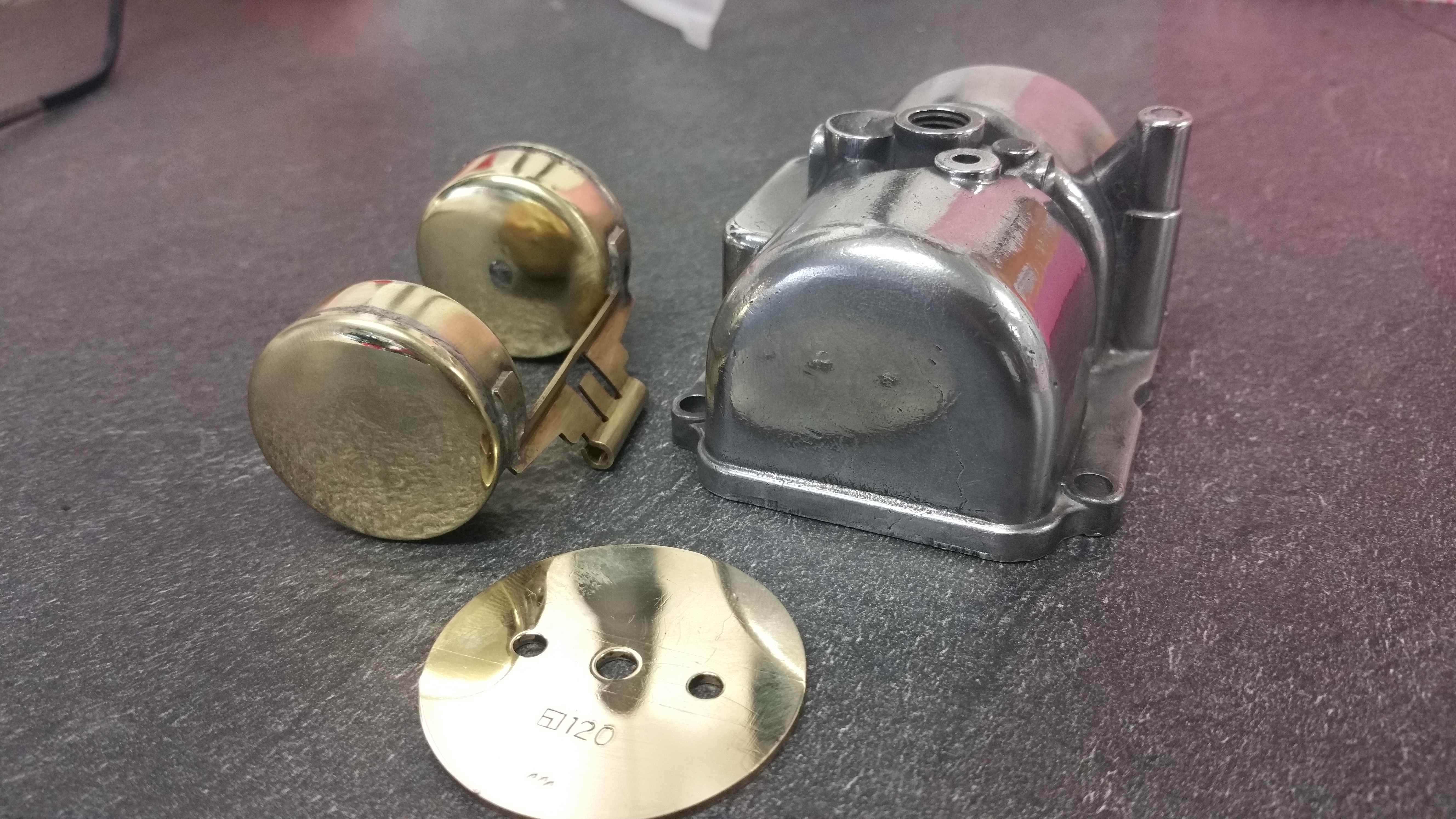
Splitting the carbs (pictures usorted at the moment )

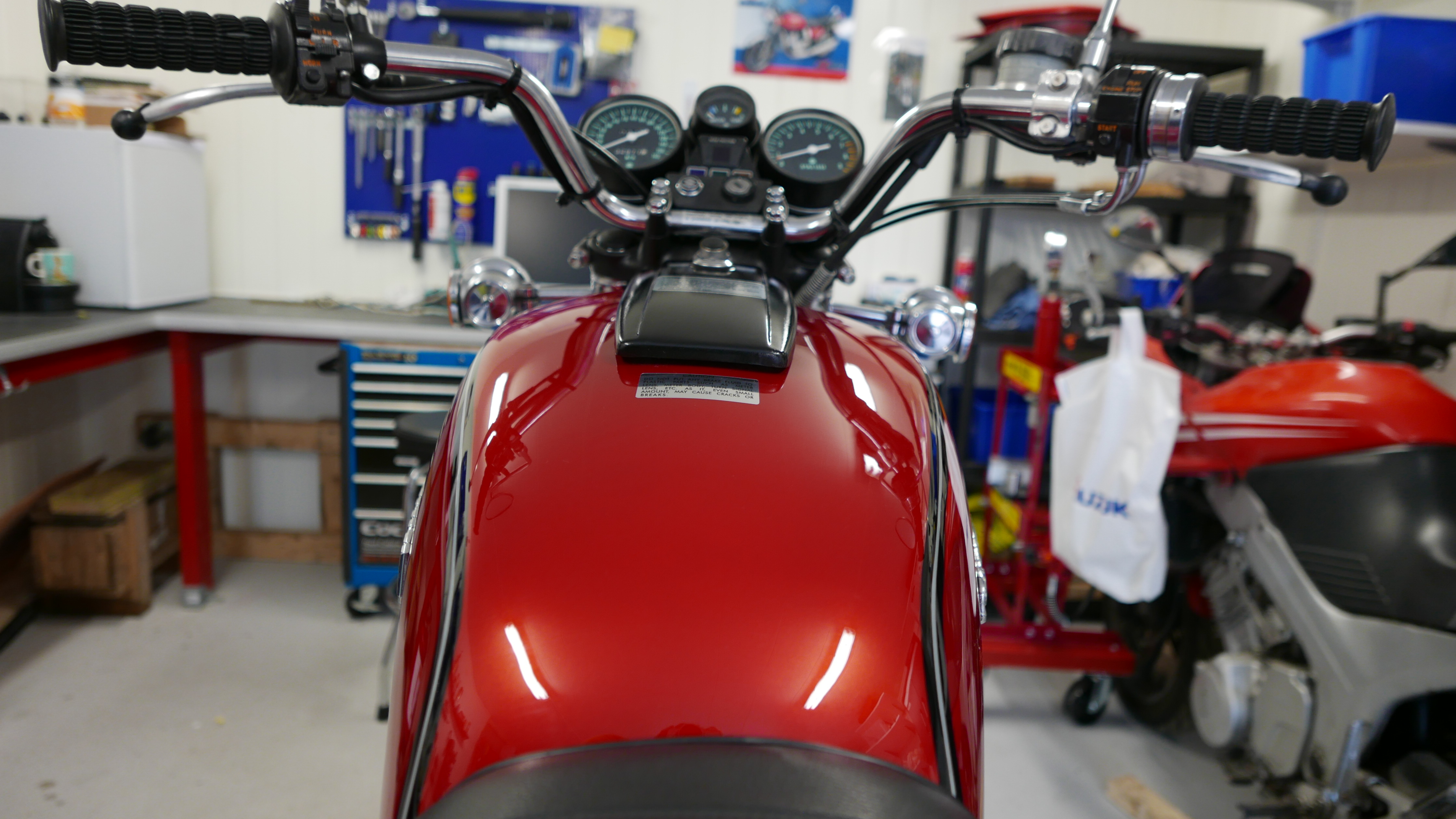
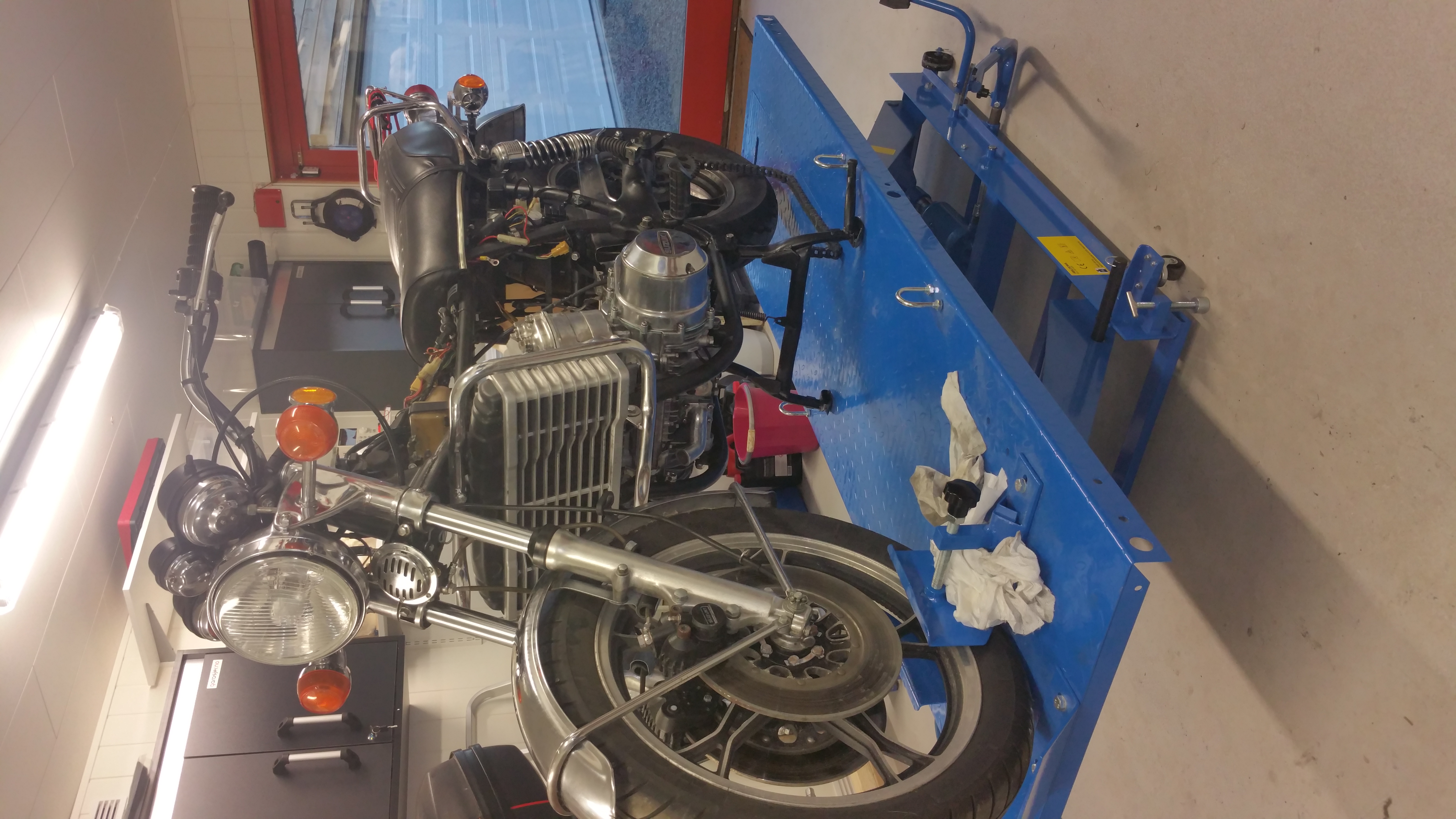
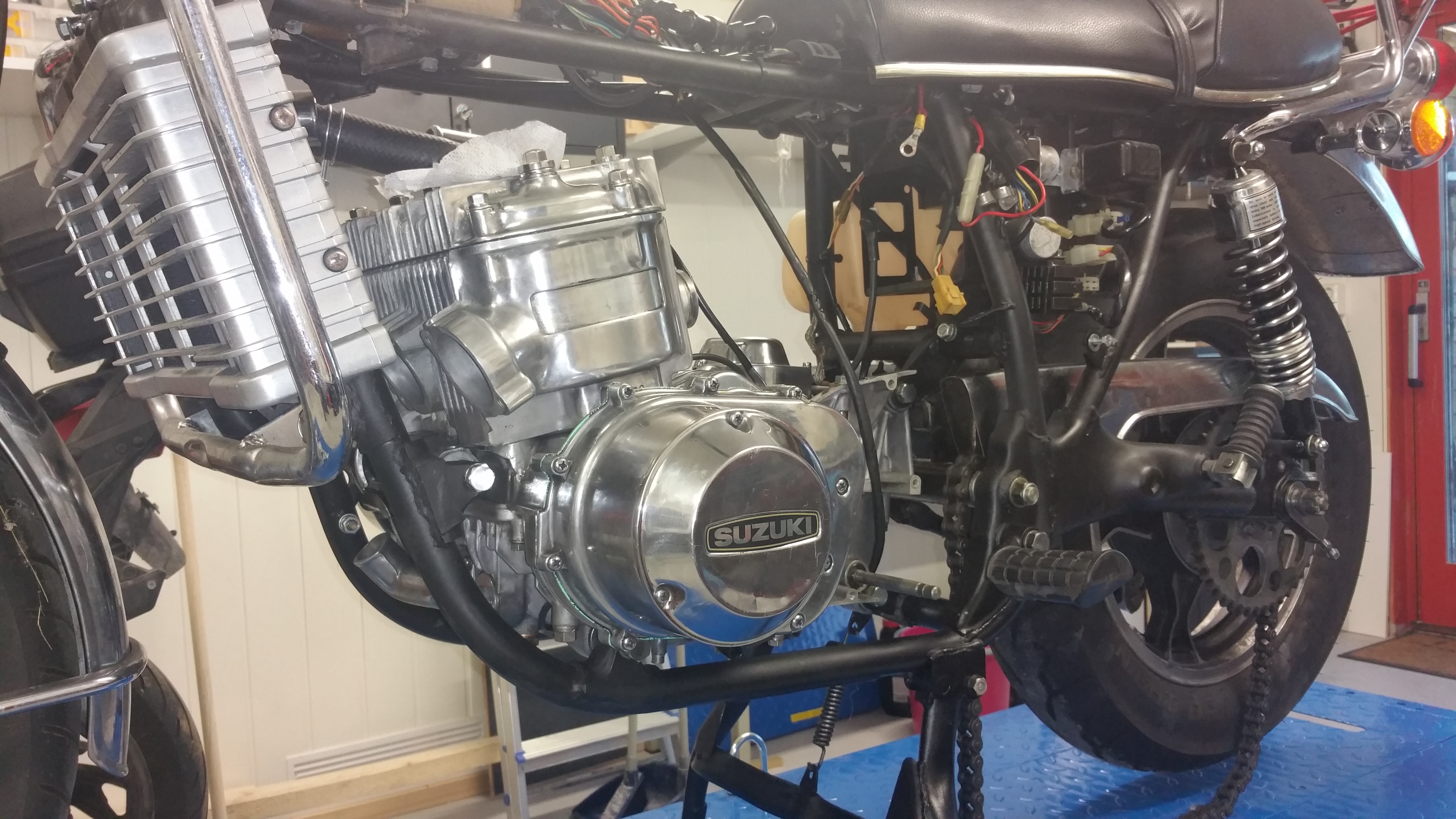
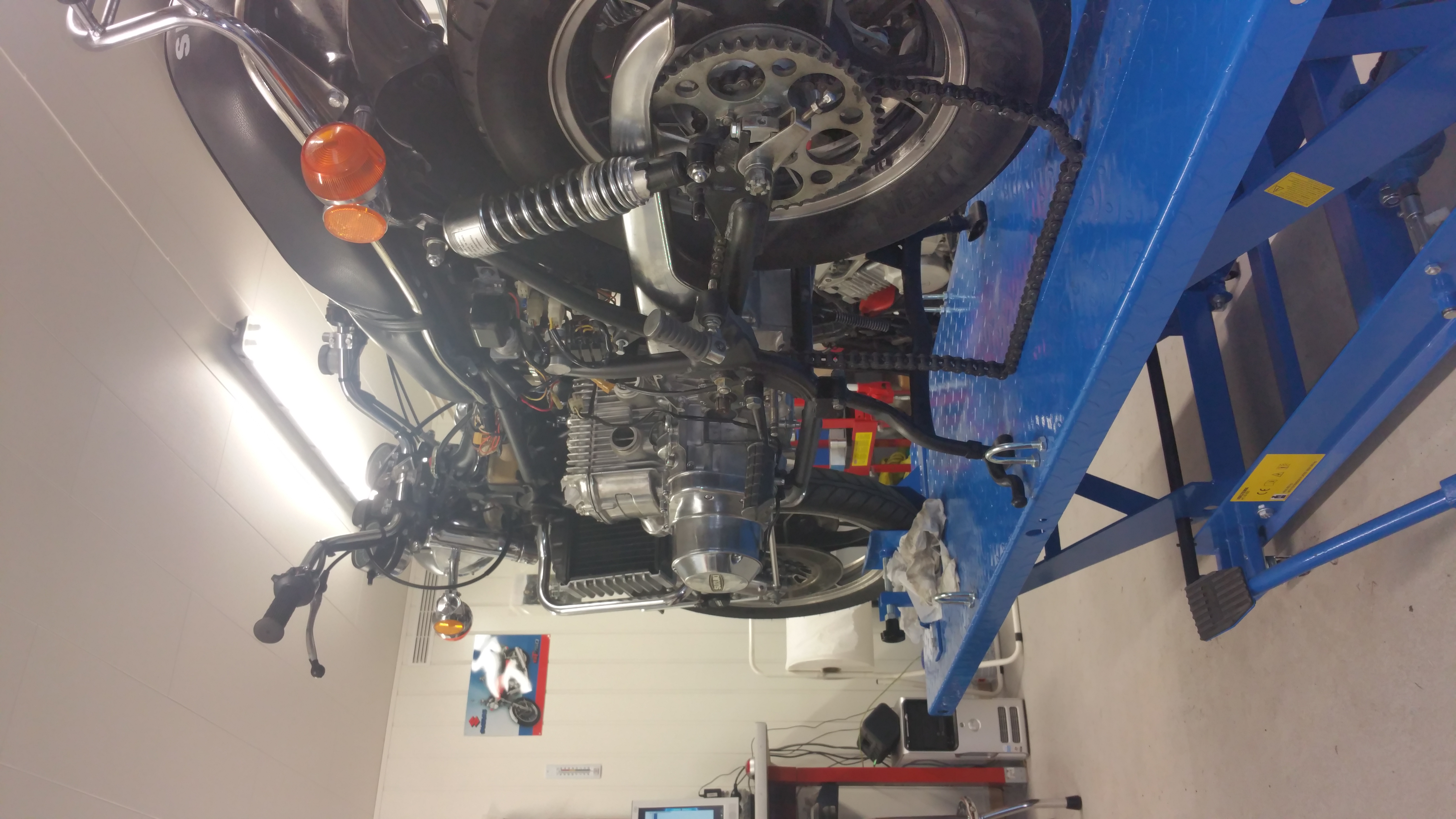
Have done some test runs and it all looks good. The first one was not, had to change the points and adjust the timing once more. Now it works fine. I’m so pleased to have the bike on the road again 🙂

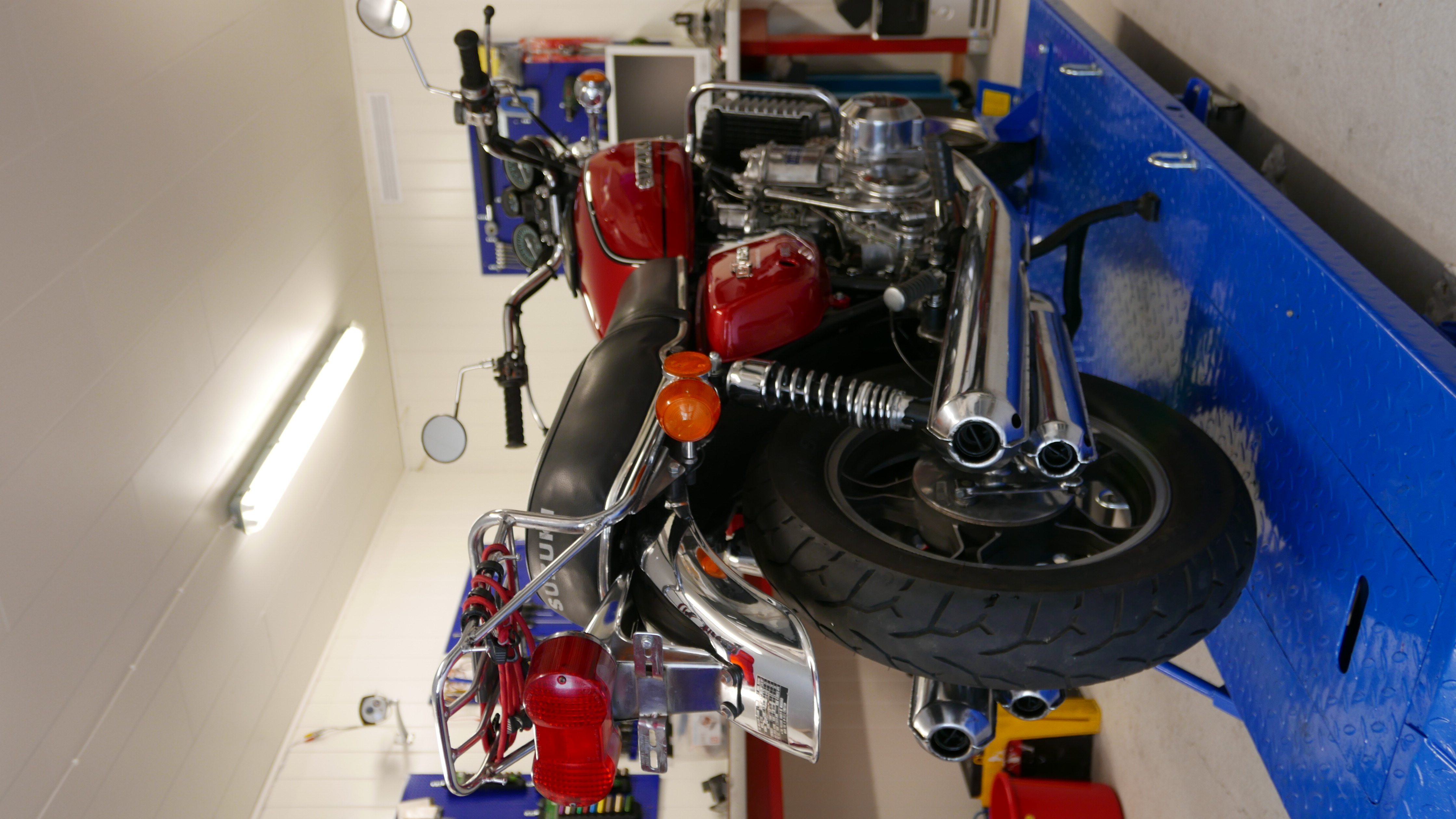
At last, almost two years since I started the engine rebuild it was time to verify if all my posts on the blog were done correctly. So far so good. Final answer will come after the first test run. Getting the license plate next week. Most of the work on the motor was done after I completed the “Man Cave” and the Man Cave was essential for a successful ending. Old and blind I need light and space for such a job. Hopefully this blog can be at inspiration for others working with the same GT 750 issues and pleasures 🙂
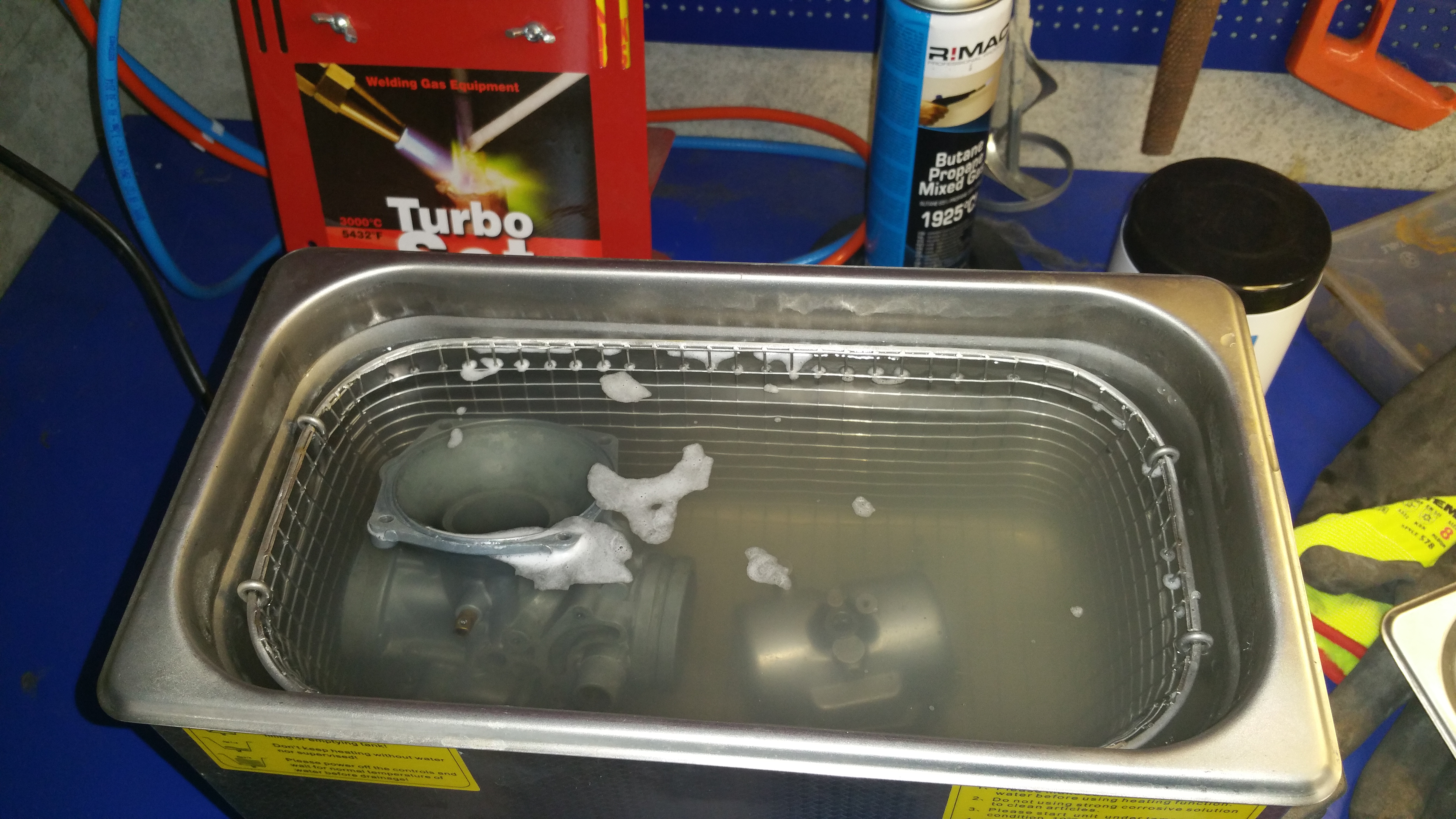
Put the kettle on:

Click on the images for detailed view


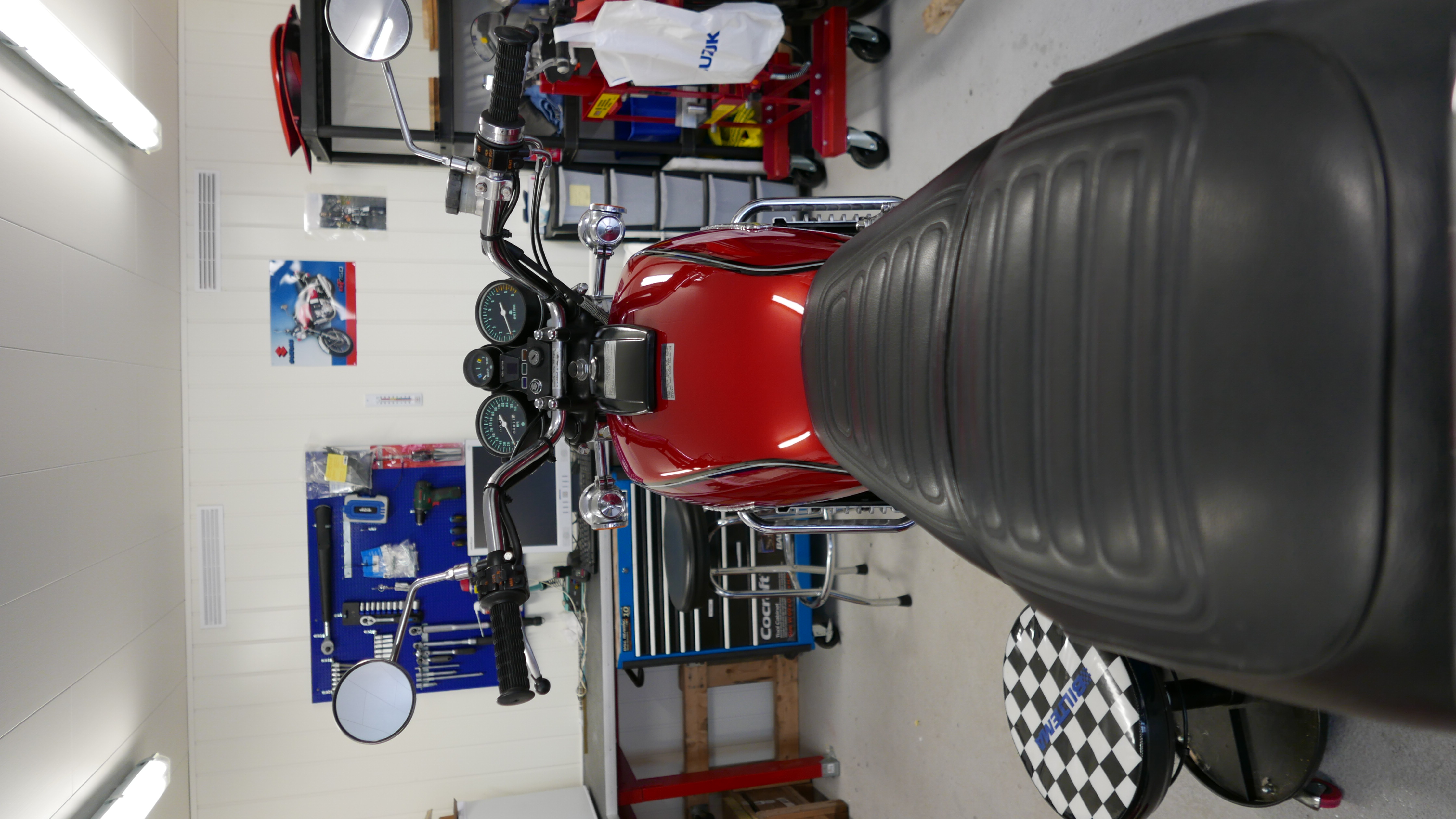
No decals are used, all hand painted by my nephew Thomas Grenasberg.

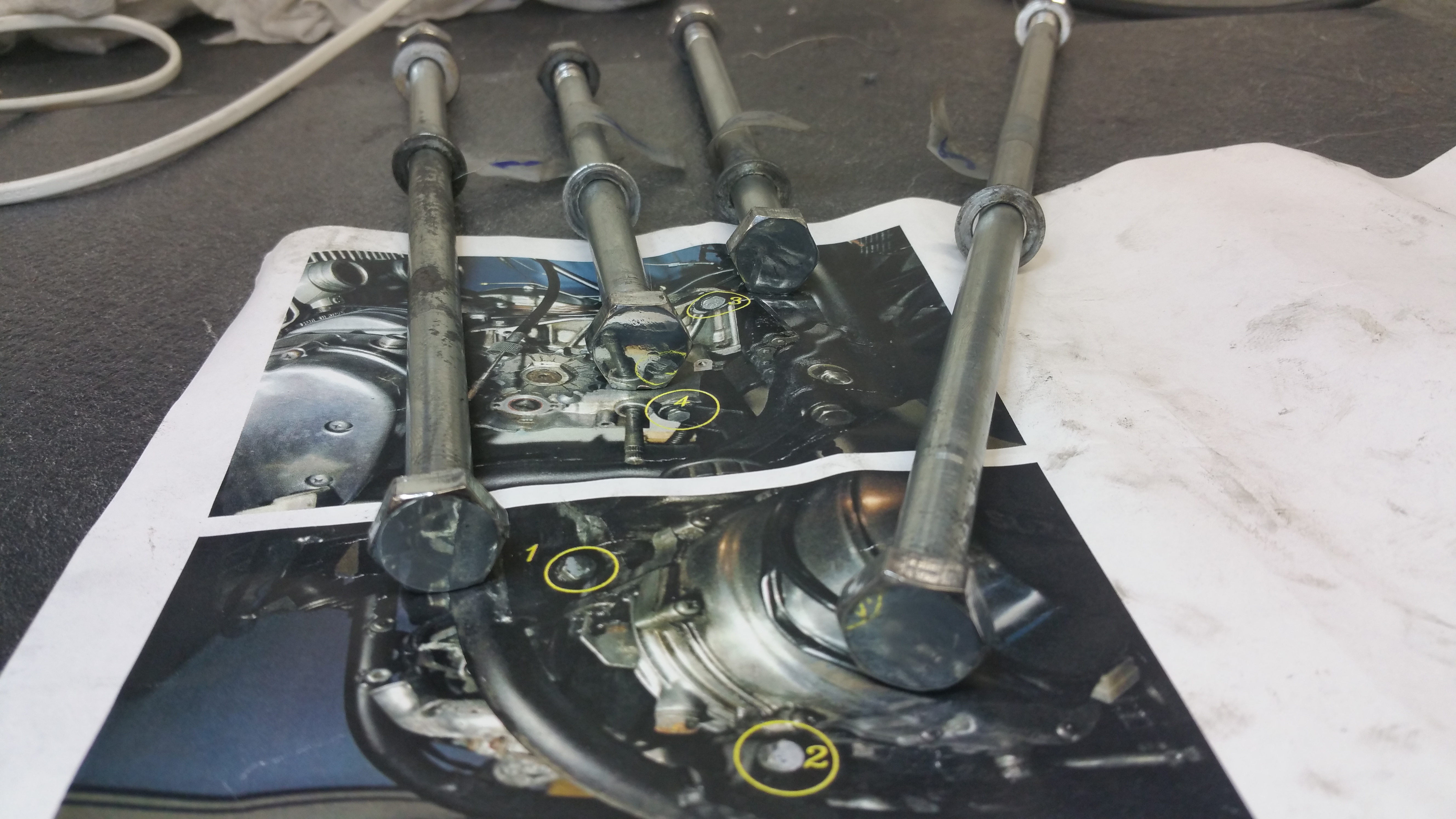
First some preparation. All four mounting bolts were labeled and shown on a picture taken before the dismounting.
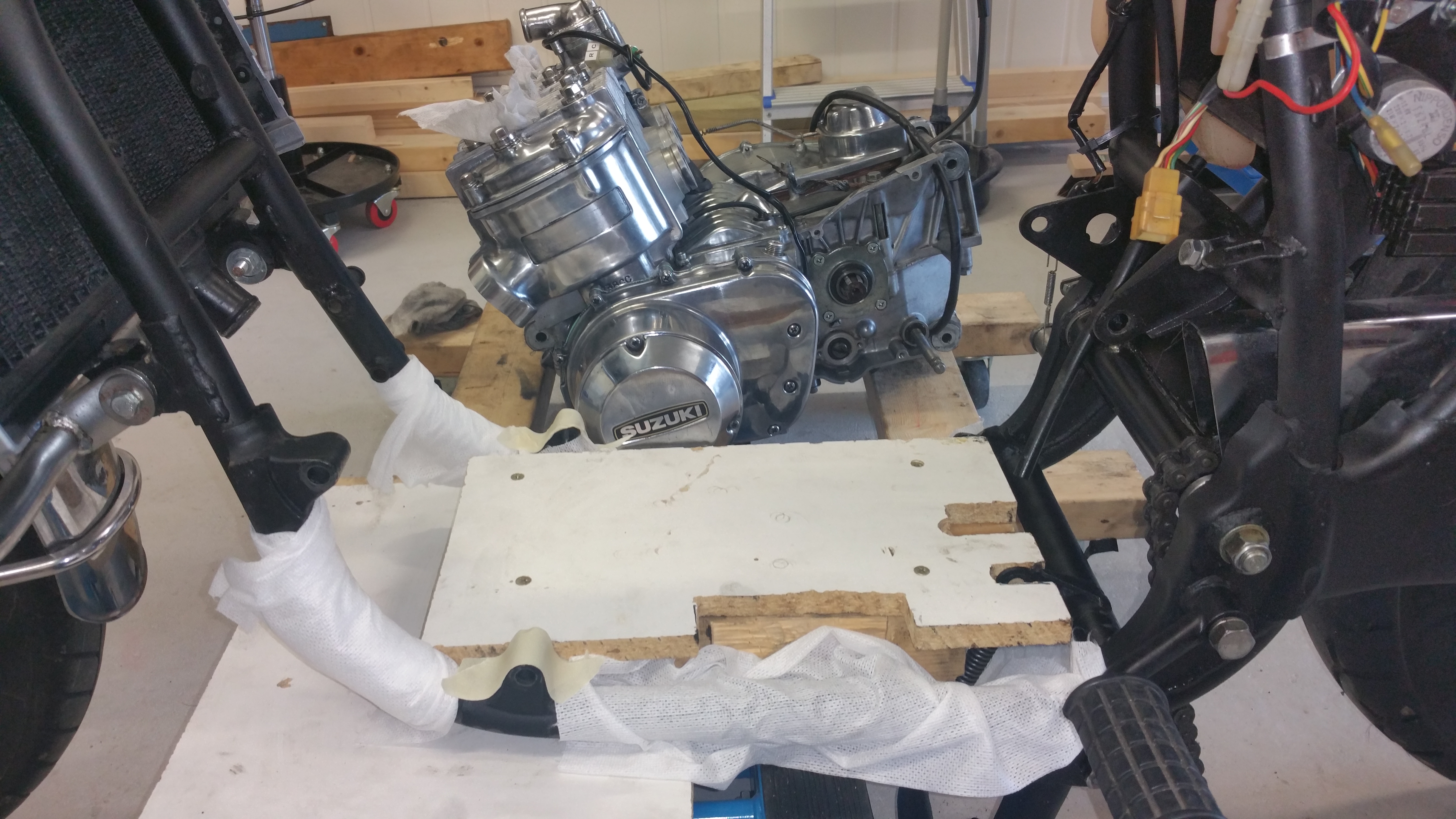
Using the small MC lifter to lower the wood frame.
Well in place on the large MC lifter
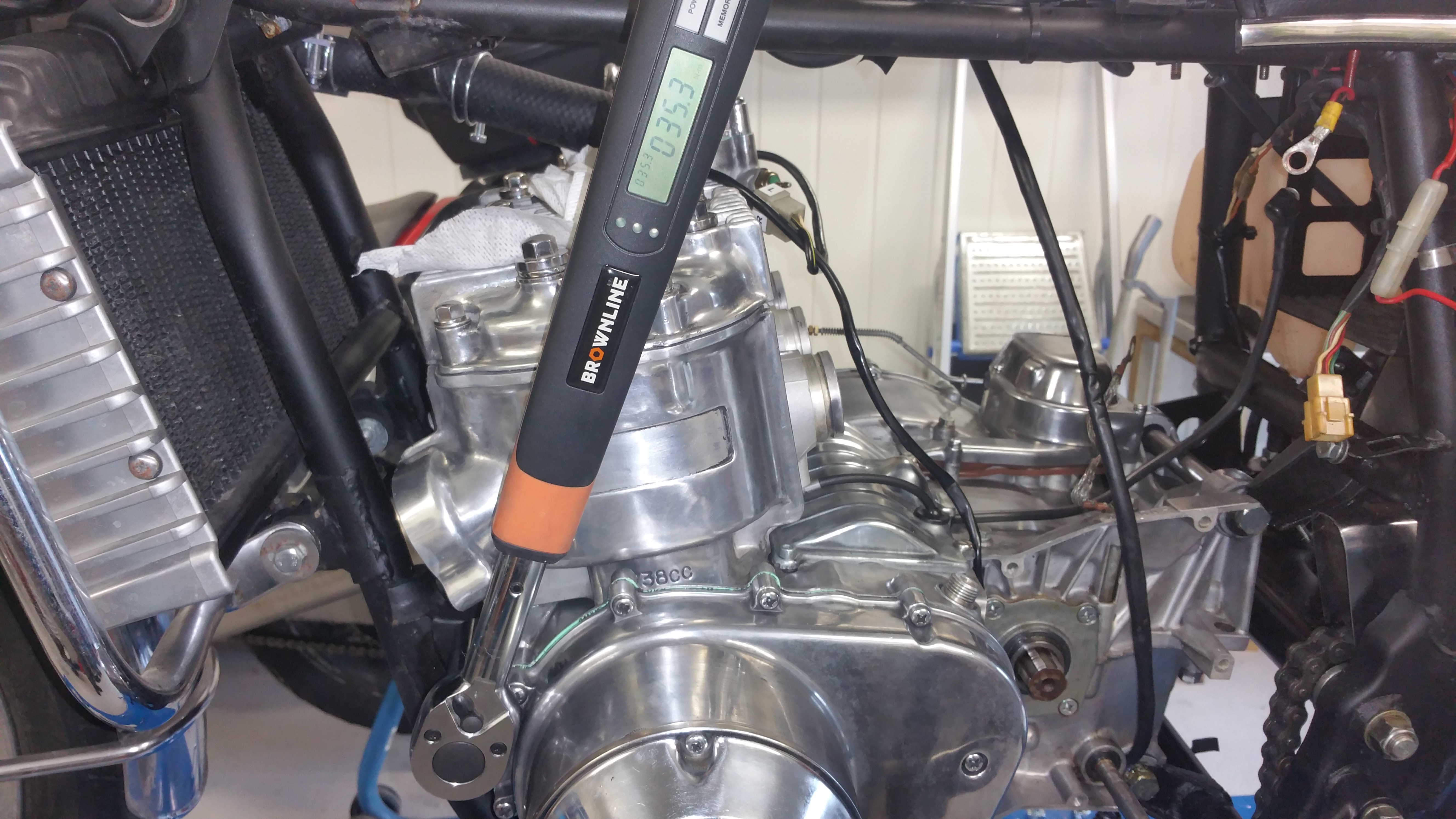
Torque settings : 35 Nm
Cylinder head:
Tightening order (red and green numbers on the bolts ) of cylinder head bolts. Red colour = 35Nm, Green colour = 18Nm
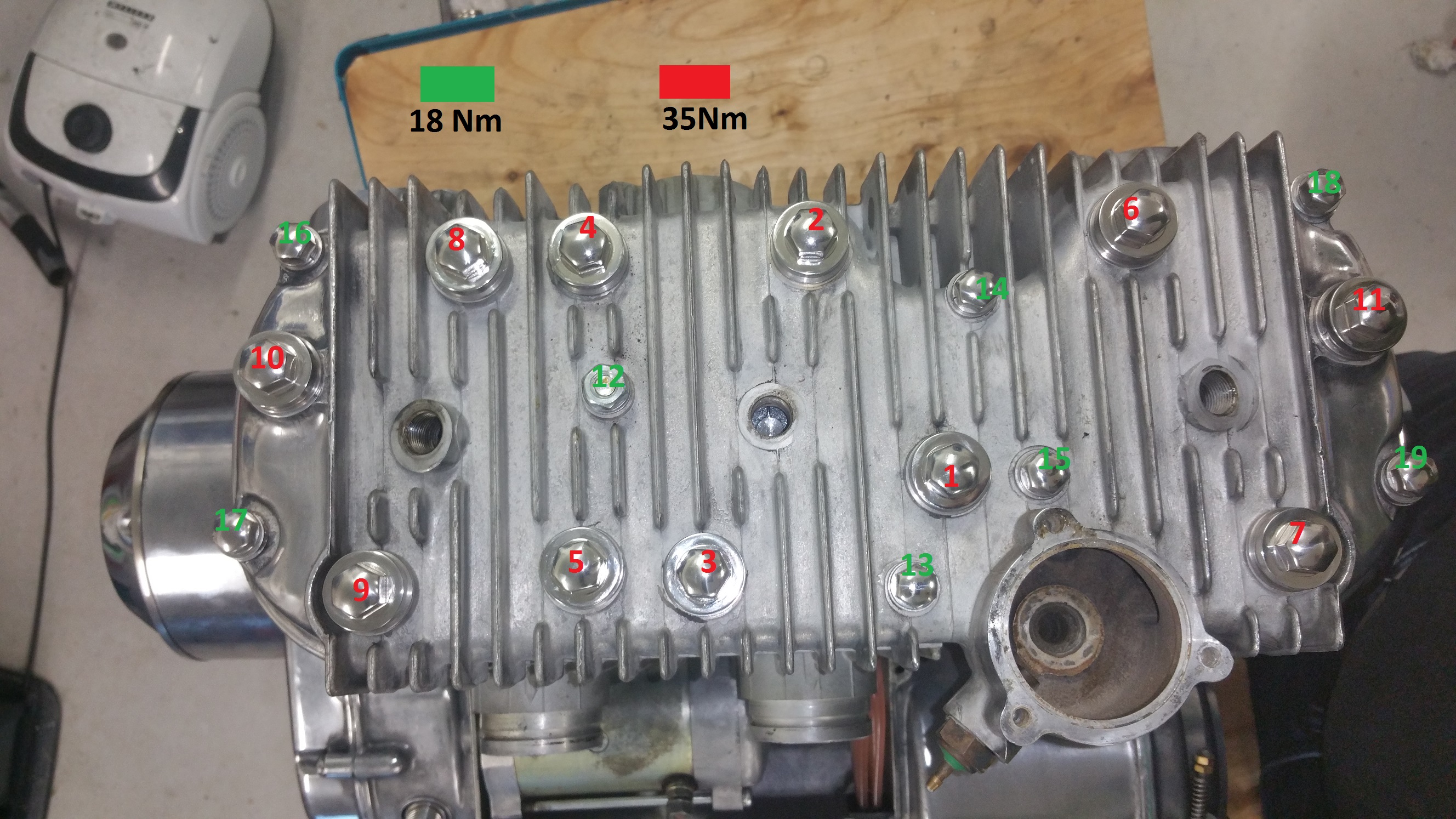
Click on the image for detailed view.
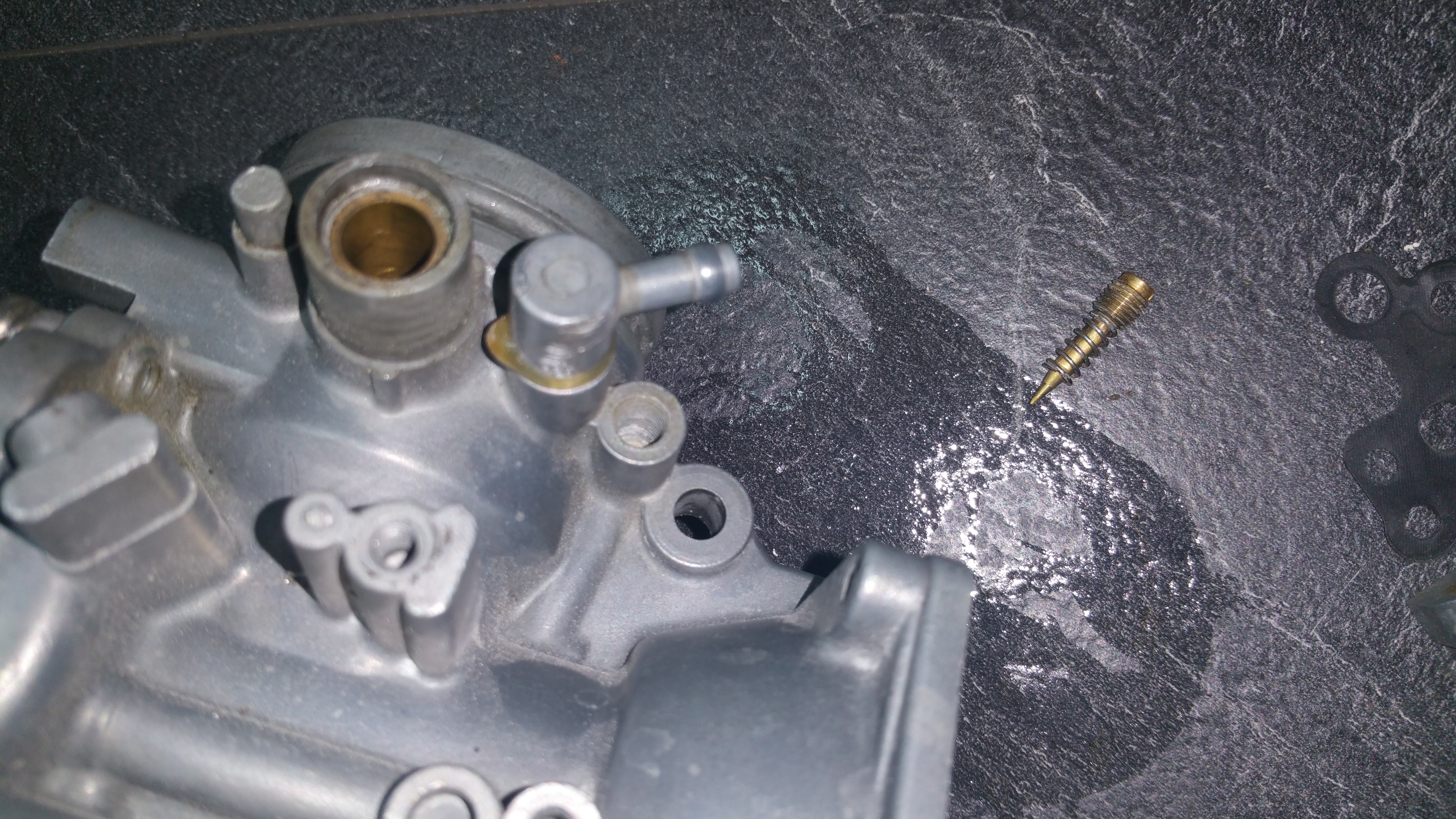
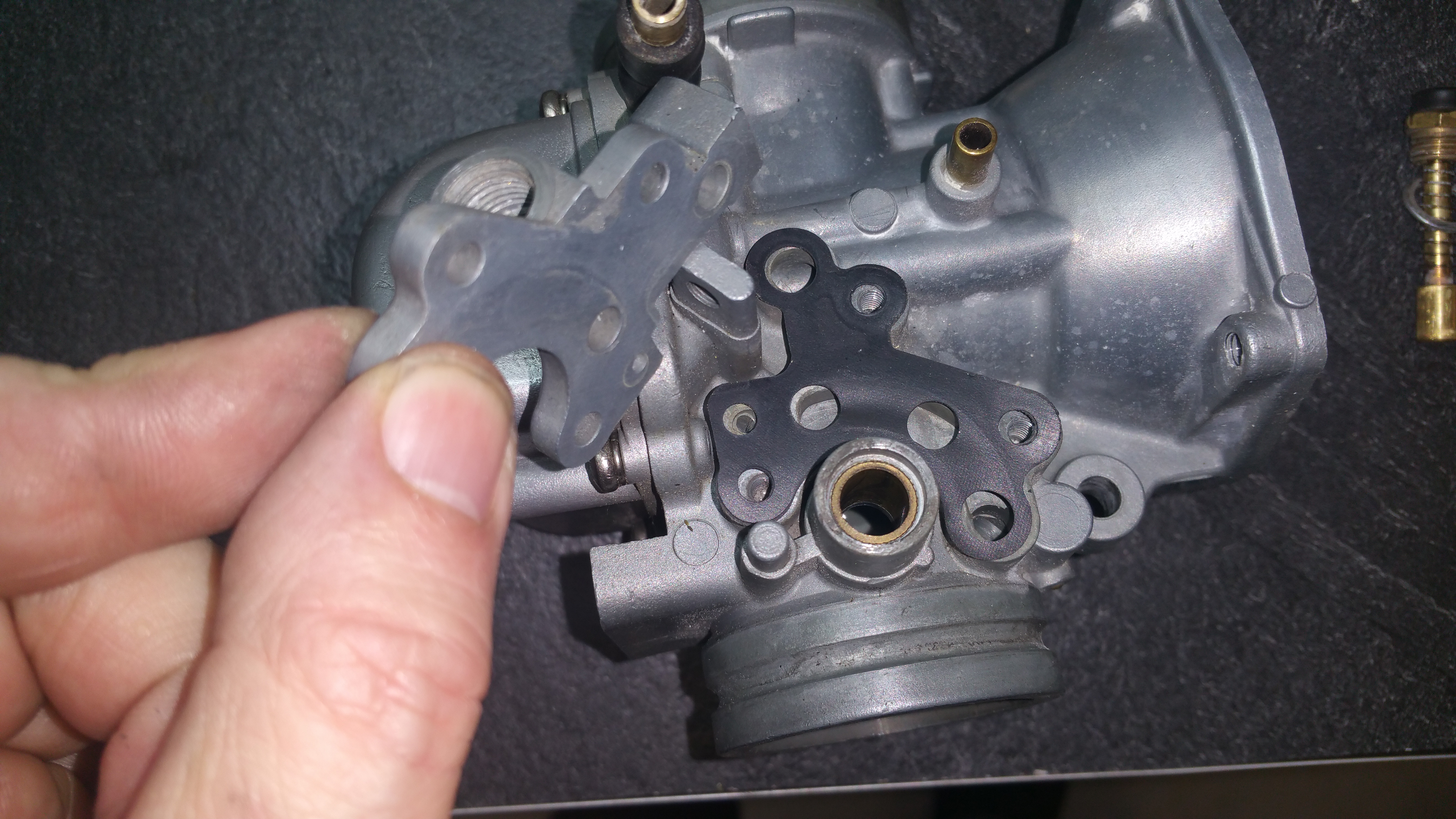
Oil pump and cover :
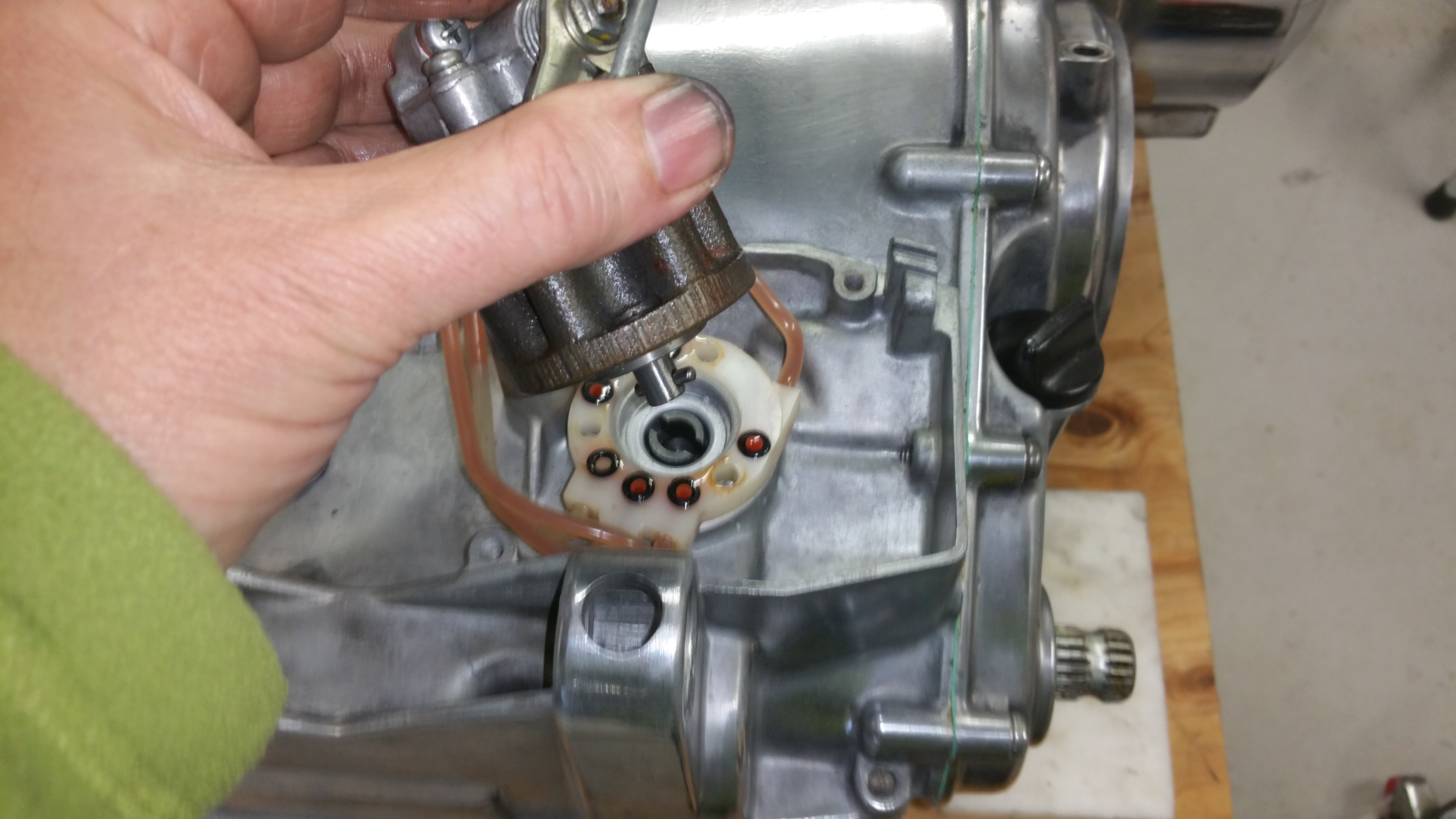
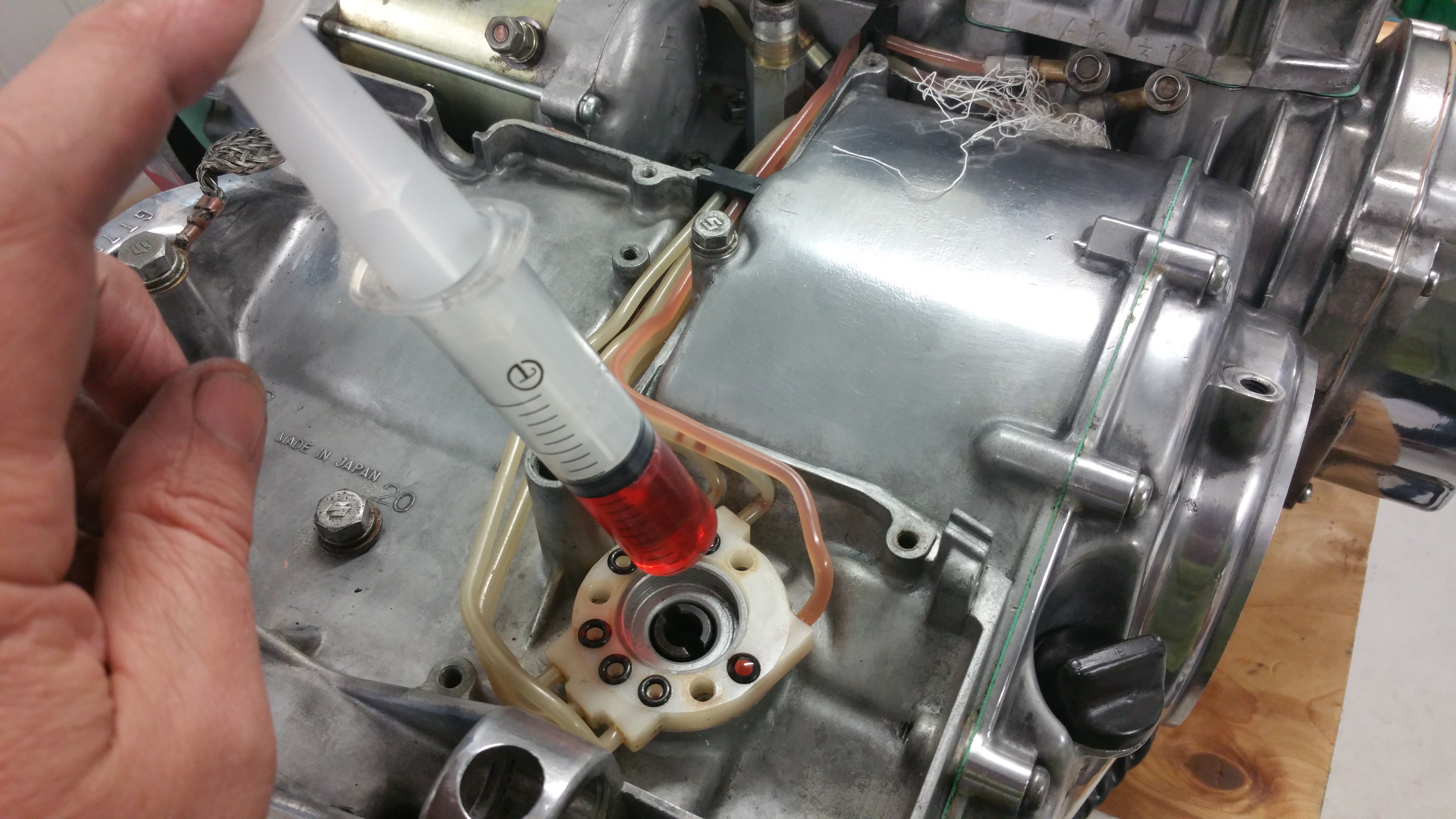
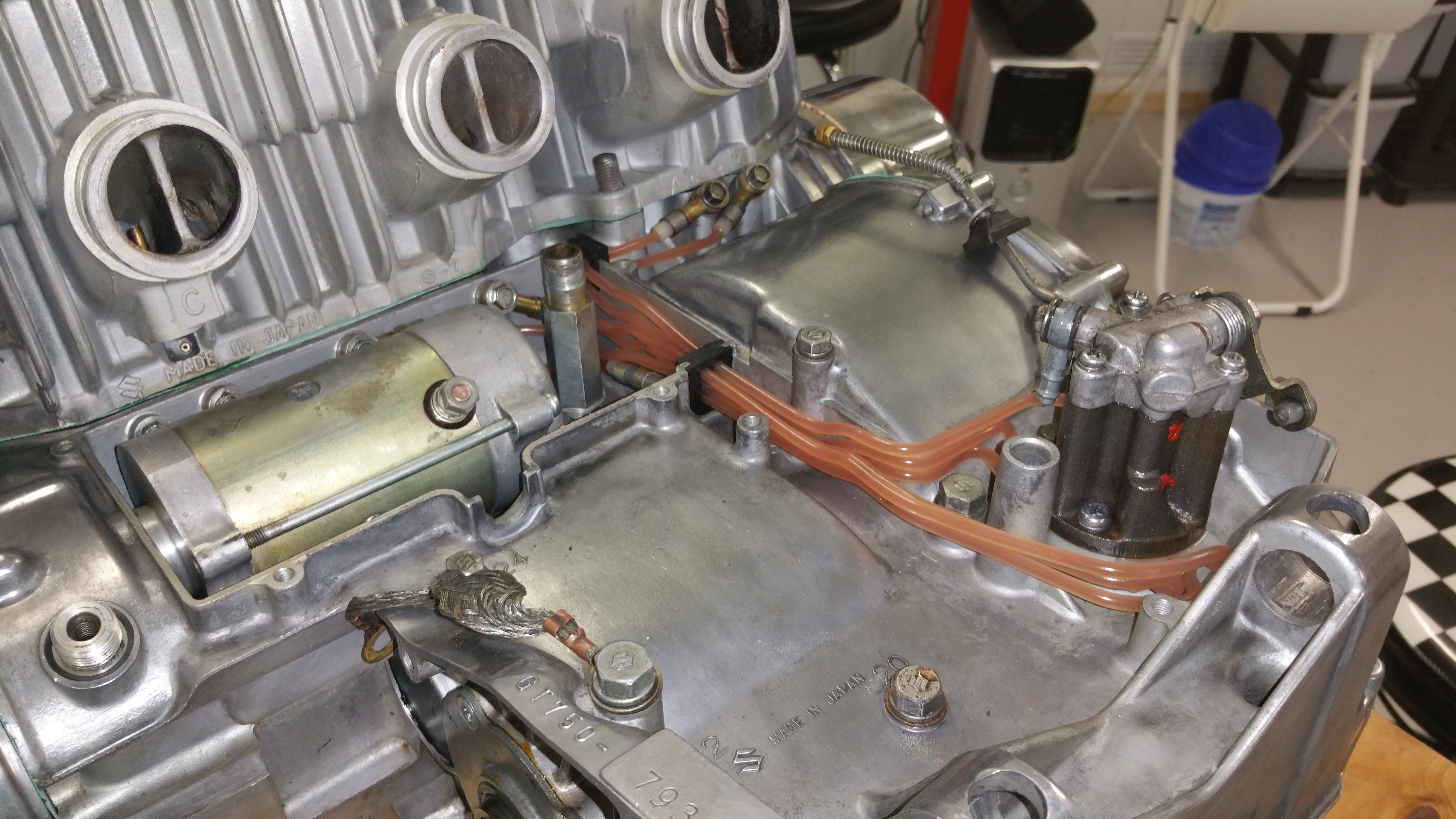
According to the information in fig 1 the SRIS tube from the front side should go from the left cylinder inlet ( see the label C in fig.2) to the center cylinder SRIS outlet port. The SRIS type 2 system. Center to Right and Right to Left, all according to fig.6-13 from the manual
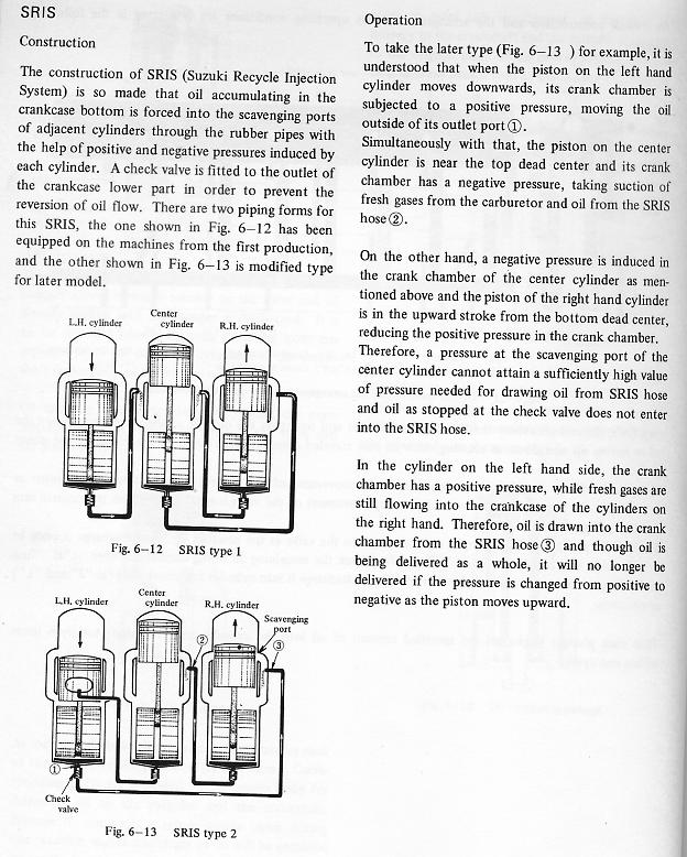
Fig.1
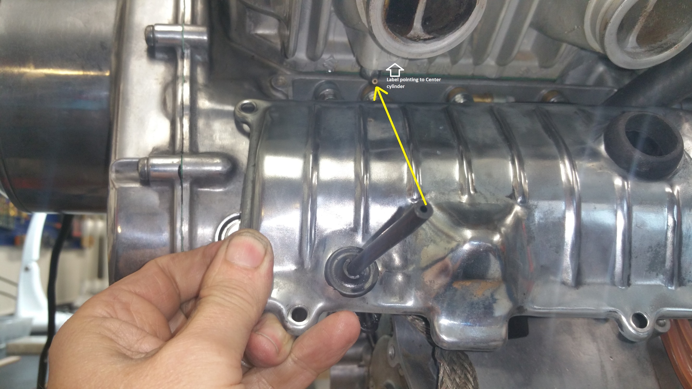
Fig.2
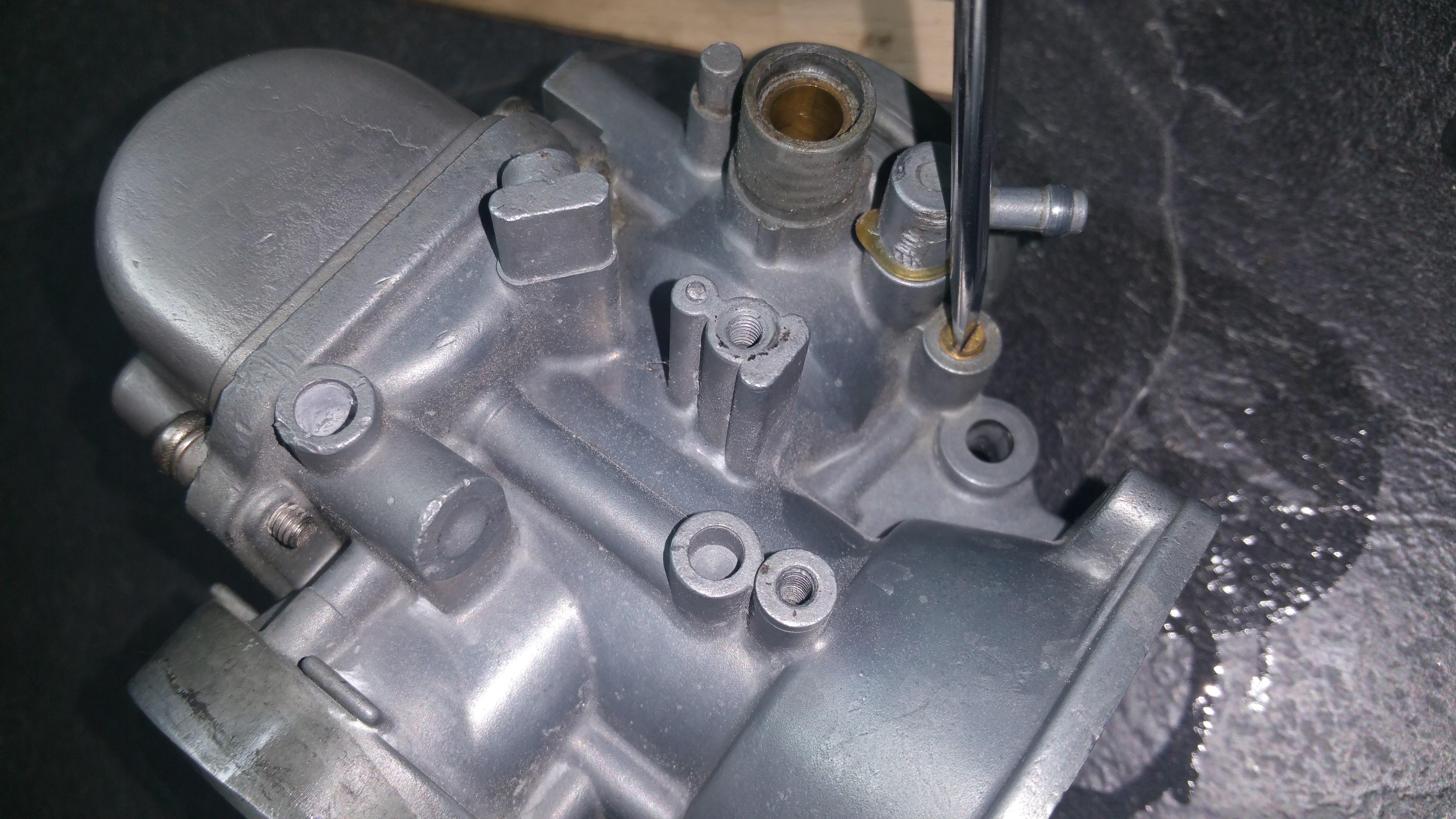
From left cylinder inlet
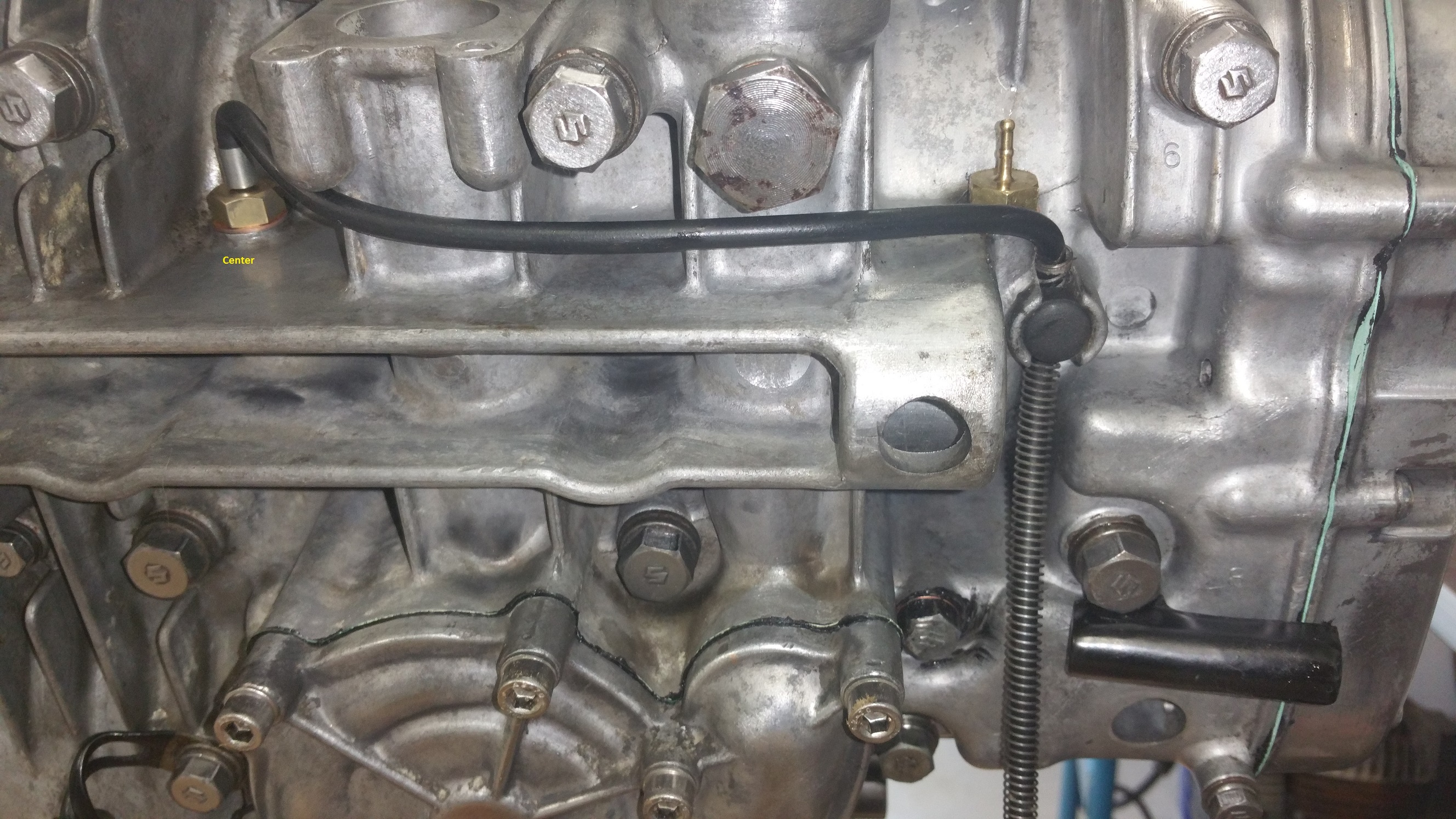
Fig.3
To the Center cylinder SRIS check valve outlet.

Fig.4
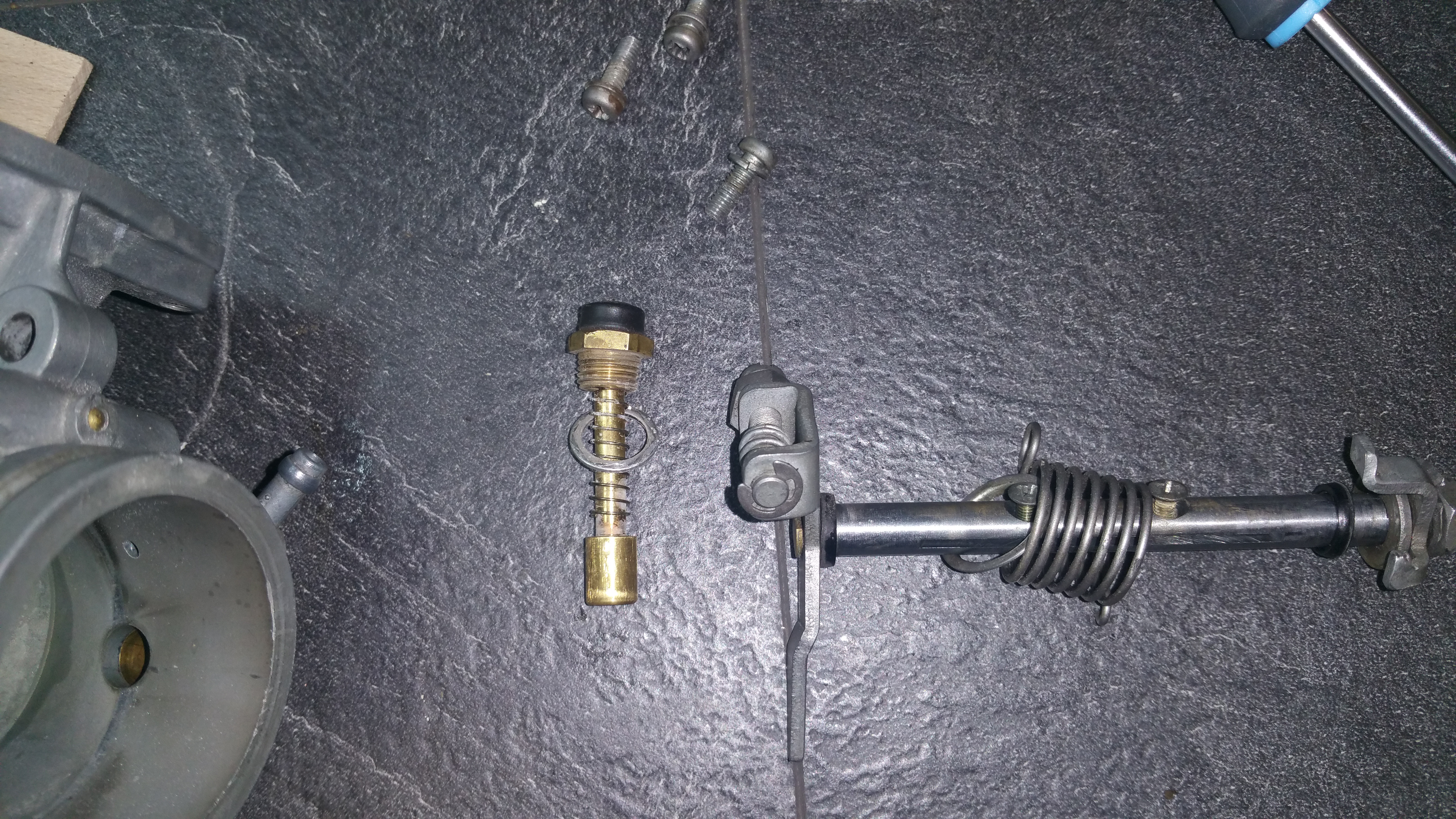
Fig.4 shows the two remaining tubes. From Right to Left (red arrow) and Center to Right (yellow arrow ) .
Adjustment procedure for setting the correct ignition timing.
Please read previous post regarding the functional description about the GT750 ignition system. This post will cover the adjustment of the points to achieve the correct timing.
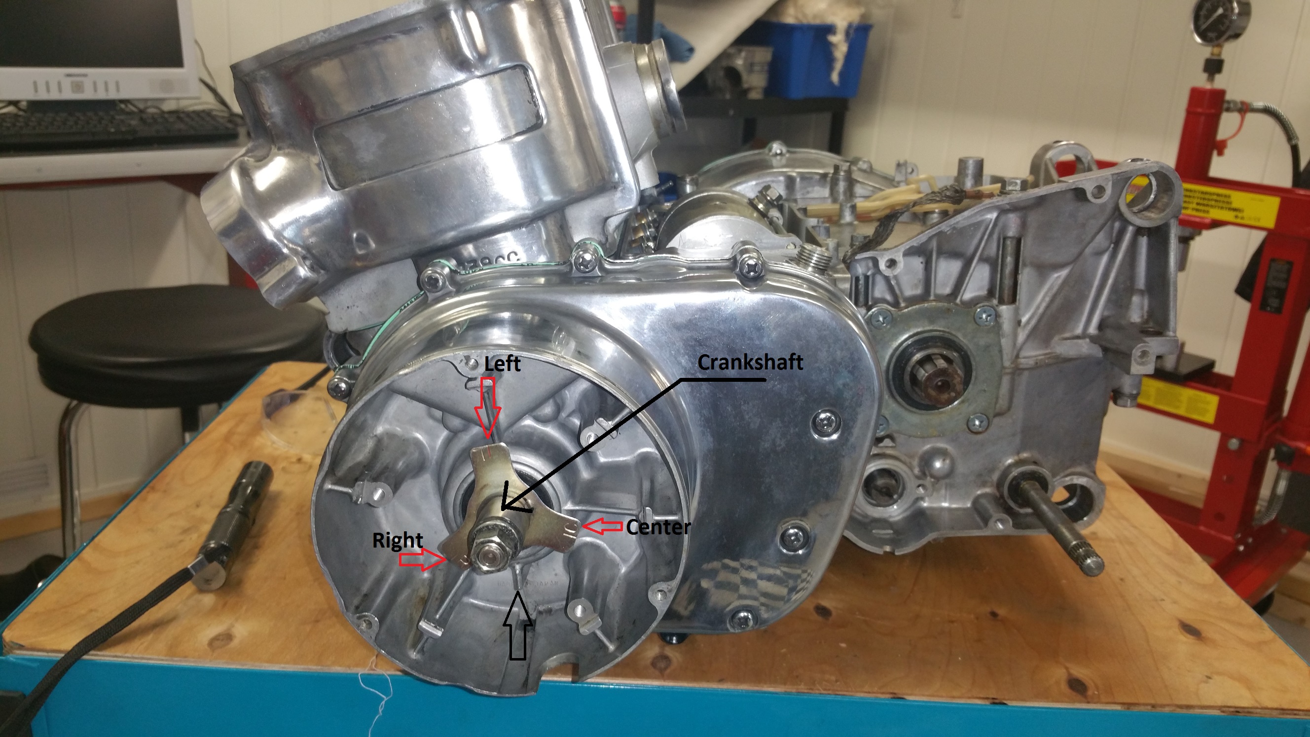
Fig.1
In fig.1 you can see the Timing Plate showing the BTDC marker for each piston. When the marker is aligned with the black arrow at the bottom of the picture the piston is 24 deg befor the TDC (Top Dead Center ) or 3,64 mm below the top. 3,64mm for L and R and 3,42mm for C piston. This timing plate was the Suzuki original idea regarding the timing adjustments and no other equipments than a lamp was needed for doing the job. Quite simple. The points should open when the markers are aligned.
That’s basically all you need to know, the rest of it you can easy figure out by yourself…
Clamp on the Contact Point base plate with all its assembly and do the adjustment.
Some guidance can be needed. Suzuki understood after a while, the procedure using the timing plate was not accurate enough. Some extra tools can also be handy for an optimized adjustment.
Tools:

Fig. 2
The Dial Gauge will be used to give a accurate measurement from the TDC down to the position where the points should open up (BTDC). I made my own instrument using a standard dial gauge and drilled a hole in a spark plug for mounting the gauge. The lamp is also self made. A LED lamp with a magnet at the end for easy fastening on top of a screw or other parts which are magnetic.
Adjustments:
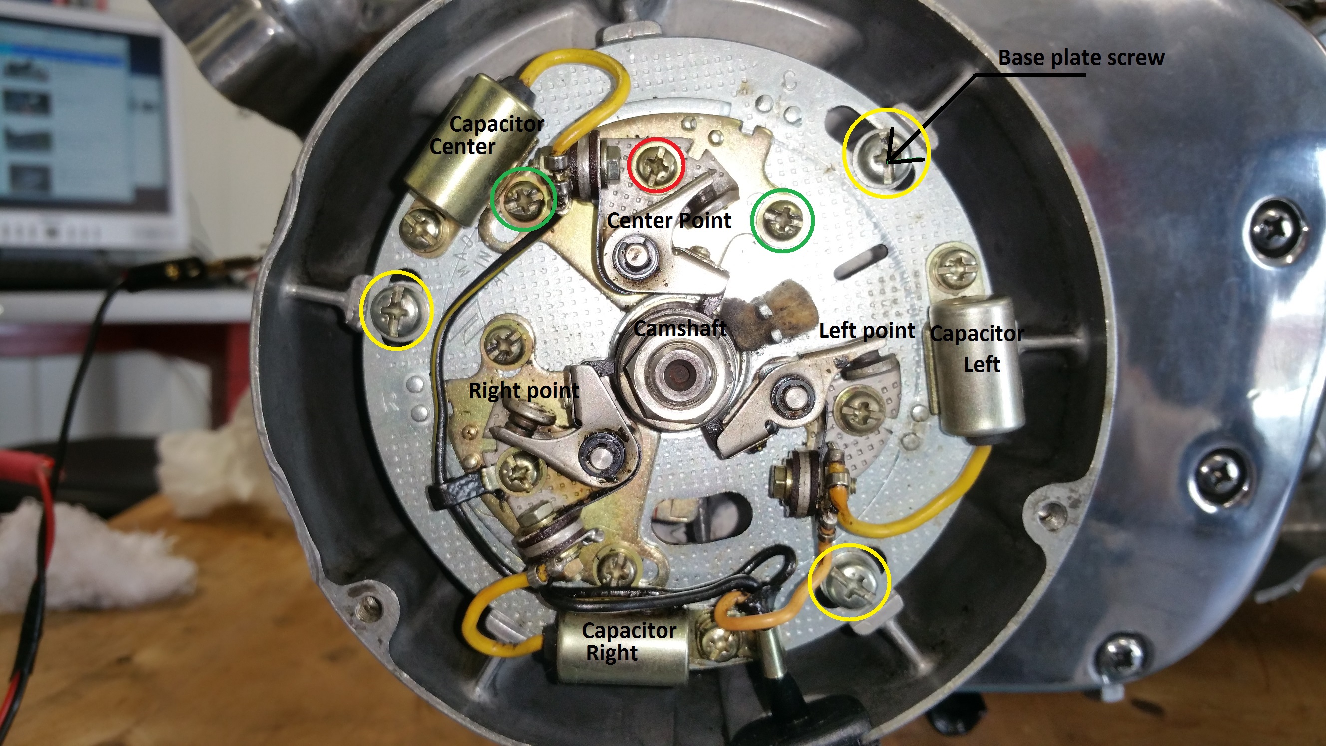
Fig 3
By loosen up the three base plate screws (yellow marker) you can adjust the timing of all cylinders. This is to be done when you install the timing plate assembly for the first time after a rebuild and you know the timing was more or less correct before the dismounting. Don’t loosen up any points individually before you have checked the timing using the following procedure:
Step 1, checking the timing the old way
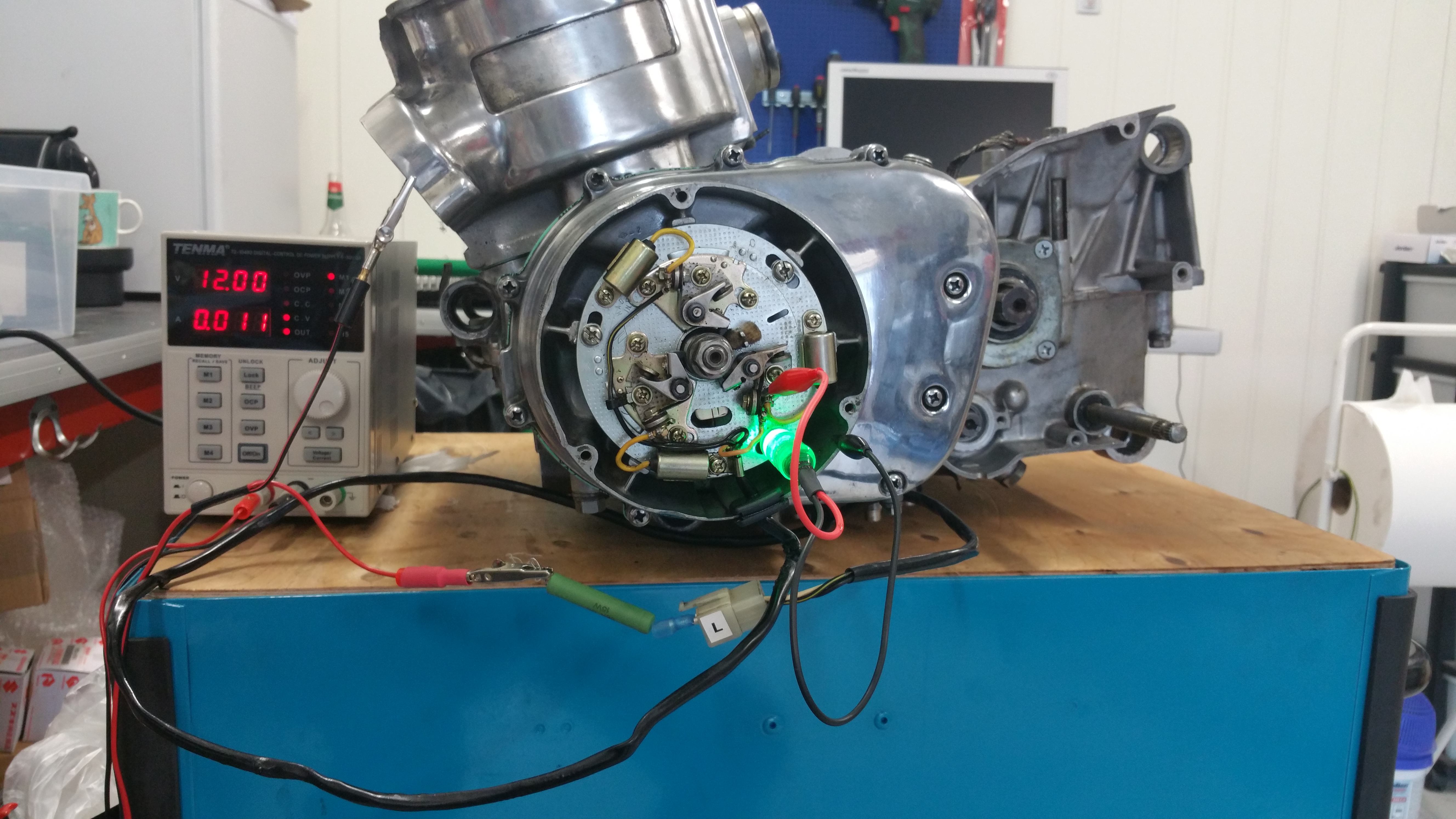
Fig.4
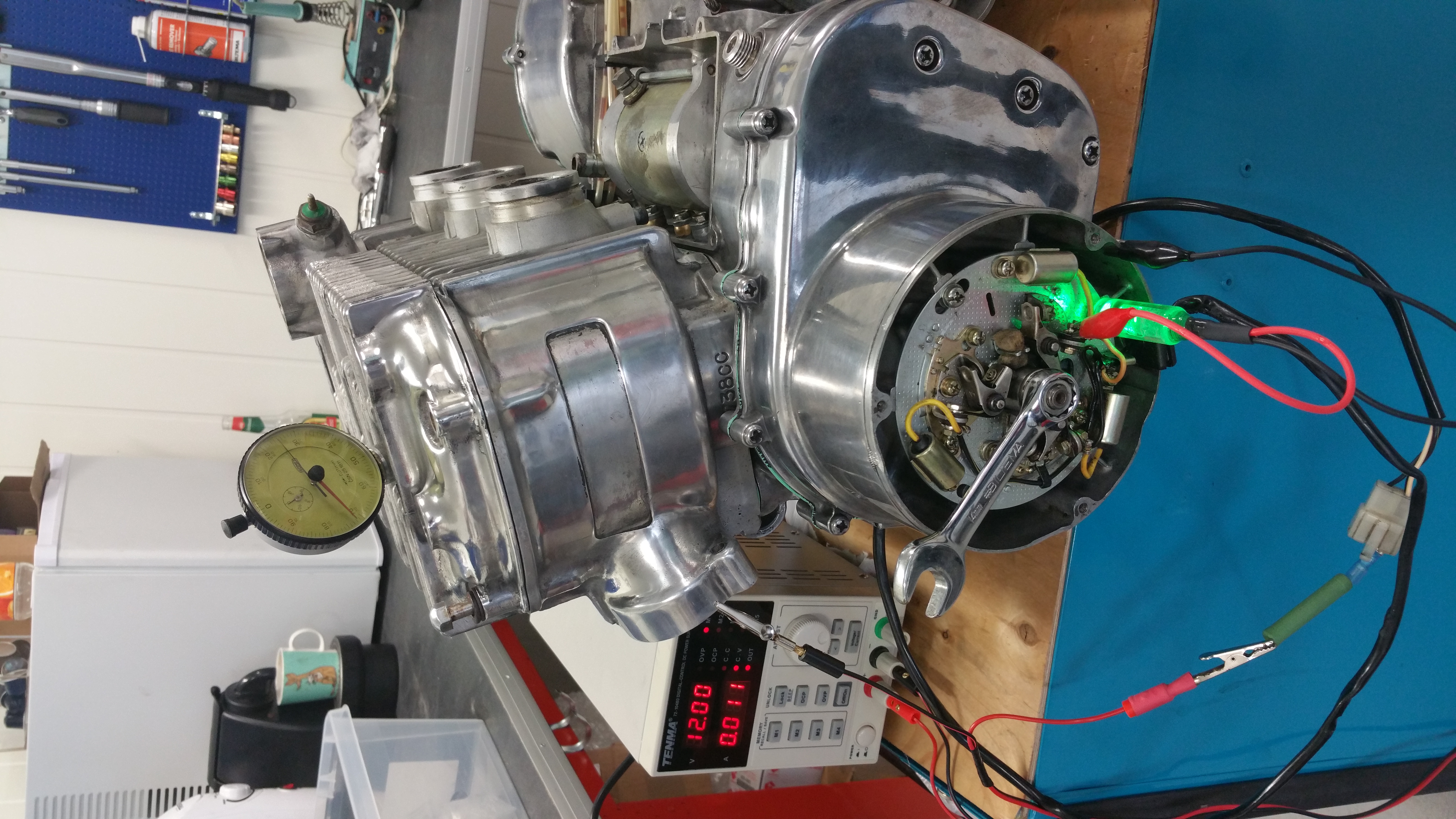
In fig.4 I do the timing adjustment using an external power supply and use a resistor instead of a coil and apply the + voltage to the Left point wire (white colour wire ) When the engine is mounted in the frame and the coils are connected the current will come from the battery trough the coils ( see previous posts and wiring diagram )
The lamp is connected to the yellow wire and ground on the left circuit breaker (left point ) If the points are closed the lamp is off. As soon as the points opens up the lamp will light. Remember, the points short the yellow wire down to ground when its closed. At open position the voltage at the yellow wire will be around 12V (depending of the type of lamp )
Step 2, restore previous timing settings
Move the crank counter clockwise until the lamp lights up. If the timing is correct the timing marker in the timing plate should be aligned, see fig.5. Red and yellow arrow on the picture shows the markers
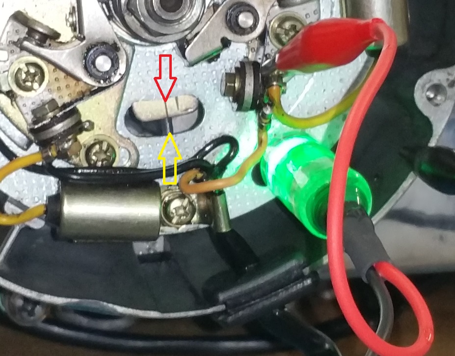
Fig .5
This is the BTDC for the left piston and the piston is 3,64mm below the top position ( TDC , Top Dead Center )
If this is not correct, move the crank until the markers are aligned and loosen all of the three base plate screws and move the plate until the lamp goes on and off. Secure the screws.
Now you are back to the original state before dismounting the timing assembly. Center and right points should also be OK at this stage if they were correct before the dismounting.
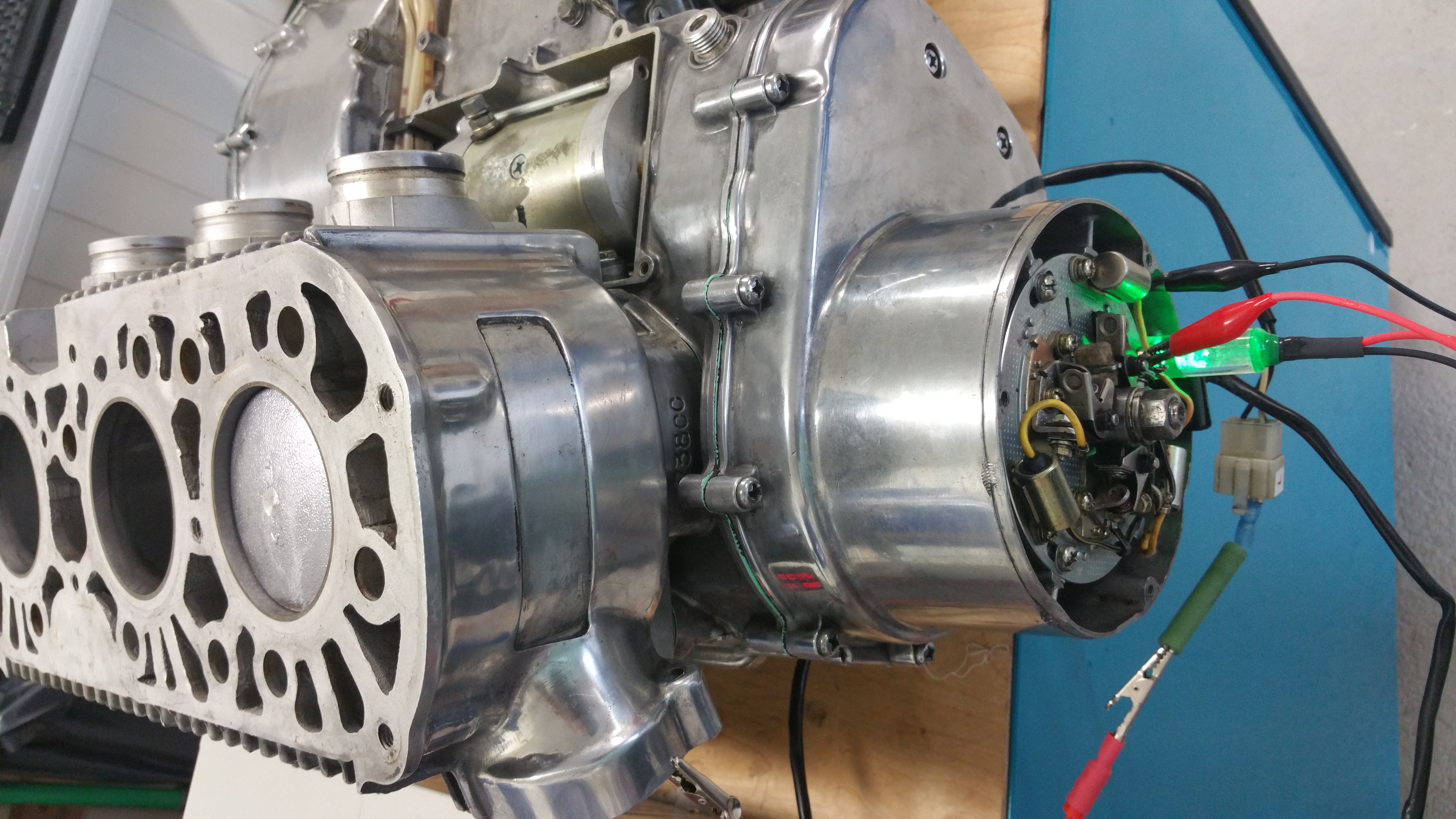
Fig. 6
In fig. 6 you can see the position of the piston at BTDC
Step 3, adjusting the points gap
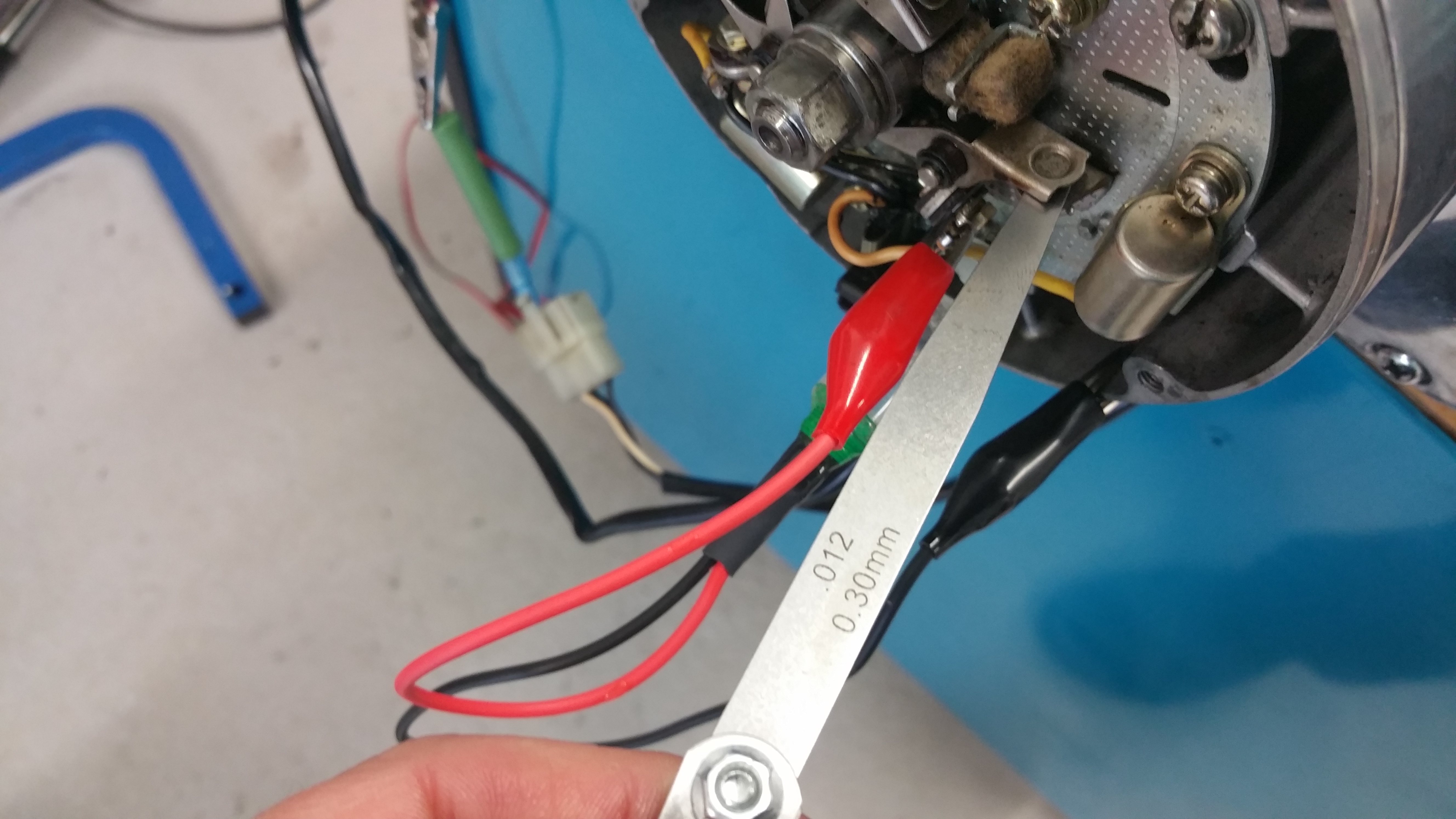
Rotate the crank until you have the maximum distance between the points. Measure and verify the gap. Should be between 0,3-0,4mm. If adjustment is needed, loosen the screw with a red label in fig.3. Check this for all of the three circuit breakers. Do this before the final timing adjustment. Any adjustment of the gap will also influence the timing and the timing has to be rechecked.
Step 4, accurate timing adjustment
As mentioned before, Suzuki recommend not to use the timing plate as the final adjustment. A dial gauge is needed to get this correct.
There are different type of dial gauges on the market. Suzuki has a special one with a zero function. I use a standard type but capable to measure several mm. Whatever procedure you decide to use, this is important : Don’t count mm while rotating backwards. From the BTDC rotate the crank the normal direction (counter clockwise). The distance from BTDC to TDC is 3,64mm for the left and right pistons and 3,42mm for the center piston.
If the timing is wrong, rotate the crank until the distance is correct and loosen the points shifting plate ( two screw with green label in fig.3) Move the plate until the lamp goes on and off. Fasten the screws and repeat the measurements. Do this for all of the three circuit breakers (points)
IMPORTANT NOTE !
The procedure above is not compliant with the procedure in the Suzuki service manual, page 94.
Suzuki use a battery driven lamp / buzzer to measure the points. The leads out of such a device gives light / sound when you short the leads. The points does this short and the lamp will therefore go out when the points open up and will light when the points are closed, exact the oposite function of a test lamp using the voltage from the battery on the bike. One more time, opposite light function compared to my description above.
If you didn’t get this, read it one more time and give it a try on the bike.