See the service manual for the procedure how to hook up the clutch cable and do the adjustments. I will also update this post later on when I do my own clutch adjustments.
The picture above shows the function of the neutral switch. The shifting switch (Part 44) is attached to the gear shifting cam. In neutral position the switch will reach the contact point inside the housing (part 39), this will lead to shortening the blue wire down to ground. Since the lamp in connected from the blue wire to +12V, the bulb will light up in neutral position.
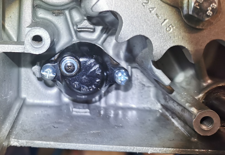
Make sure the contact points are cleaned and polished at the inside and outside of the housing. I added a new washer and screw too.
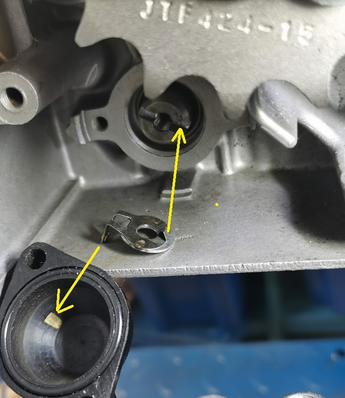
Before mounting, put the engine into neutral position. Make sure the switch is mounted with the lip into the groove at the end of the shifting cam. If so, the contact point in the switch will meet the contact point in the housing.
To verify the function, measure the conductivity from the witch down to GND. Should be a short (close to 0 ohm) when the engine is in neutral position.
When you add the wiring harness, the blue wire from the alternator cable should be fastened to the switch.
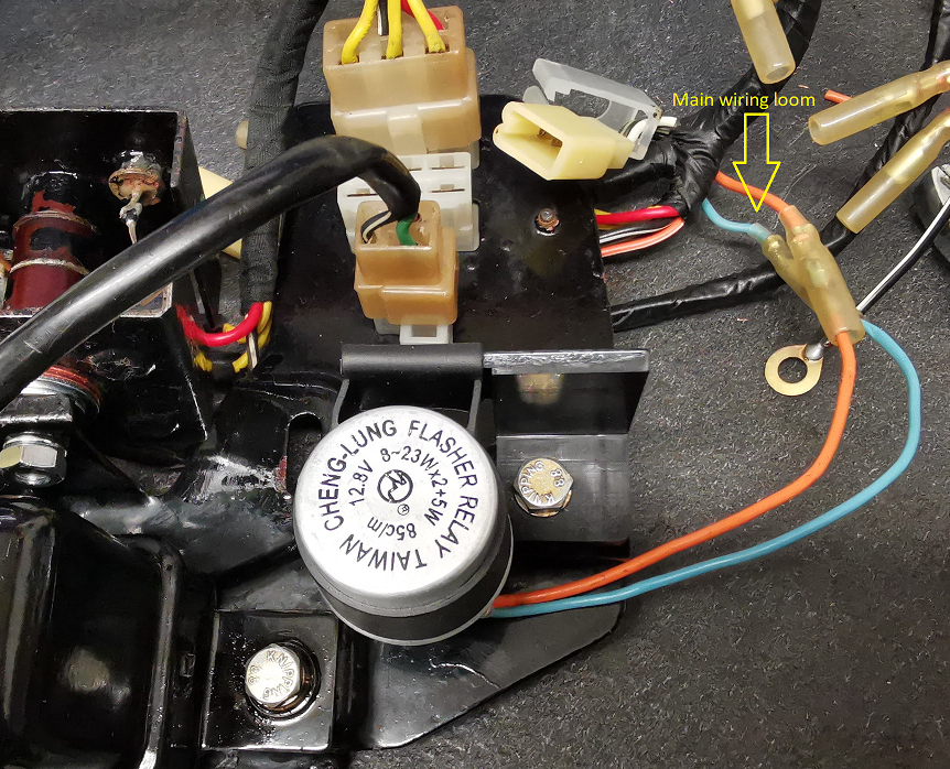
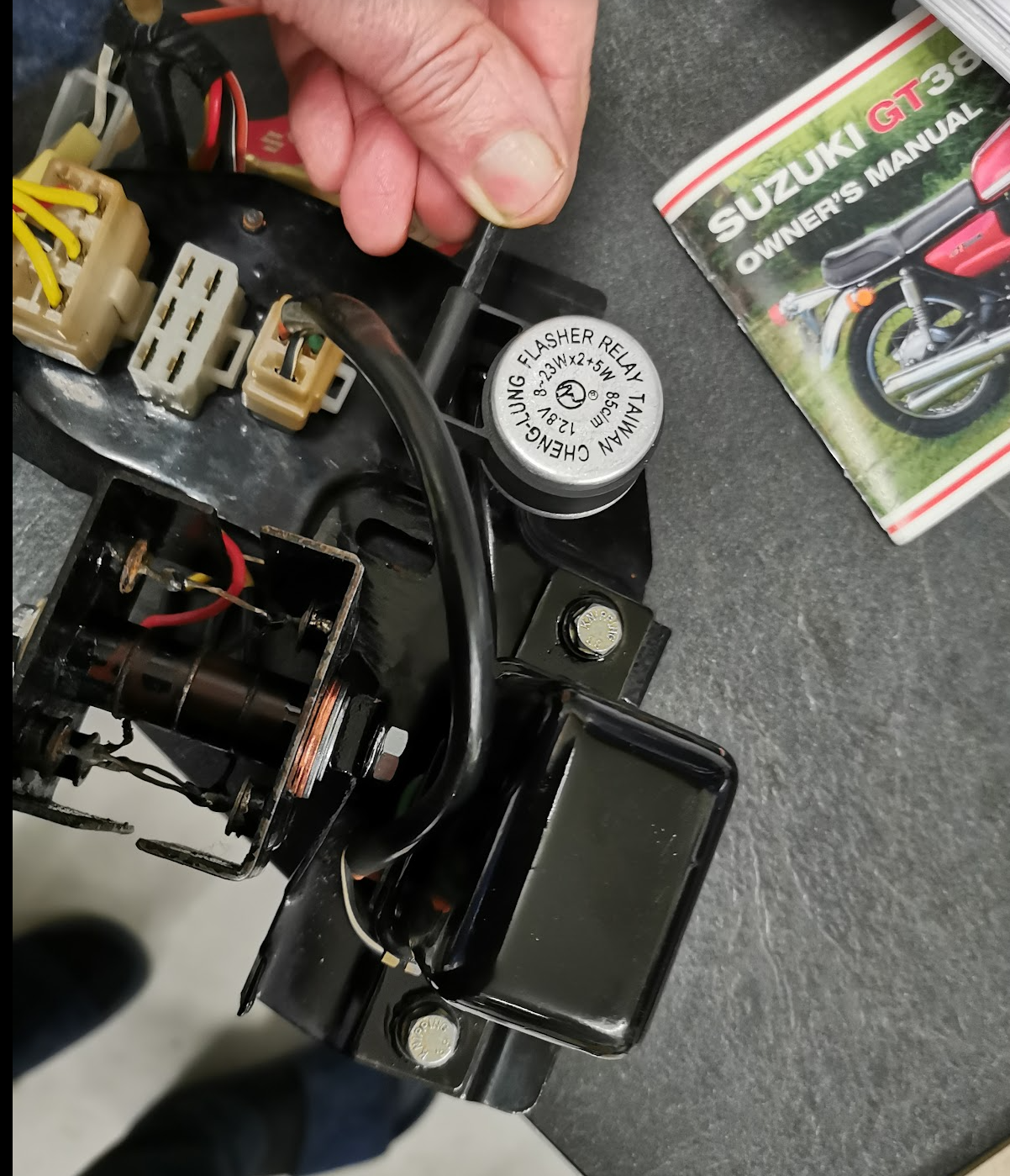
The original indicator relay was missing on my GT380J model. A ugly replacement relay had been fitted, but was not properly fastened in the rubberband due to its square shape. I had to go on Ebay to search and found a round type of relay, a bit smaller compare to the real thing but looks nice.
Because it’s smaller I can’t use the old bracket with the rubber mount. I made a resin 3D printed bracket so I could use the rubber mount that came with the new relay. Like this:
Resin printed and cured with UV light.
The STL file of the bracket can be downloaded from the link below.
New terminals to the wire so it will fit into the original wiring loom from Suzuki. I also did a test of the relay to verify the function.
Important to use the correct color coding. Orange to the + wire (orange wire is the + battery voltage after the ignition switch) and blue to the indicator lamp. ( the casing of the indicator must be grounded. Note! the blue wire to the indicators will not be blue all the way to the lamps, please see the wiring diagram for details. The 2-wire relay is connected in series from the battery (after the ignition switch) to the indicator lamps. Controlled by the switches, left and right lamps will then get the voltage applied from the blue wire on the relay.
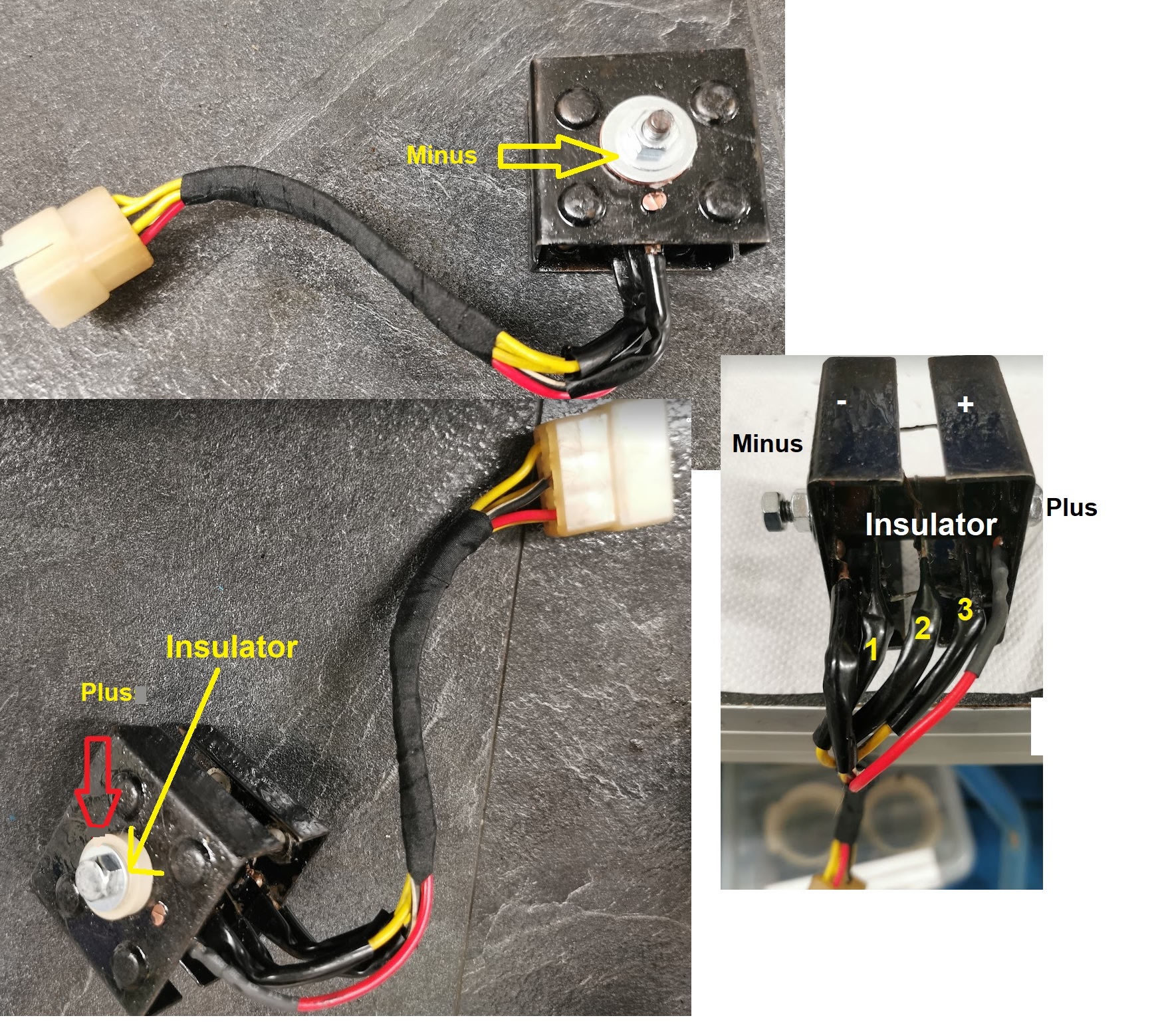
Mounted together with the rectifier and the regulator relay.
Note! The rectifire in the picture above is mounted different compare to how it came with the bike. I turned the recifire upside down and made a proper ground to the negative part of the diode casing to achive a better ground down to the frame. The + part with the insulator is therfore at left side of the picture. Please see my previous post about the rectifier:
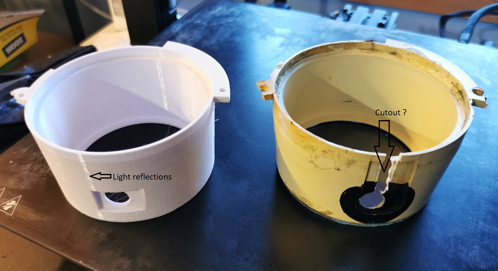
This is how I made the inner housing for the speedometer. I did the print in white PETG, able to withstand higher temperature compared to PLA filament. The STL file can be downloaded for free from the link below. Can be printed in with support to the build plate.
The original housing had a cutout for the reset-knob for the trip counter. Don’t know why, but it is probably done because difficulties when mounting the clock with the knob attached?
For the rubberpart sealing the reset-knob shaft, I will make my own fix. Can’t be bought so I will try to make something from a rubber tube and see how it works. If I face any difficulties when assembling and need to modify the 3D model, I will upload a new STL files on this site.
The orange wire is the +battery voltage, but after the ignition switch. The green wire is the +voltage to the rotor and the white and black wire is the GND wire.
The regulator on GT380 and GT750 works in the same way. The purpose is to control the rotor current and thereby adjust the magnetic field so the generator (alternator) and rectifier gives about the same outputvoltage regardless of the rpm.
The case got sandblasted and repainted. The contact breakers in the relay were sanded a bit to achieve a good connection and the current flow was thereafter tested with a power supply.
The pictures below shows the different stages from 1-3 depending of the voltage to the relay coil.
The diagrams are a bit difficult to read, they are only meant to be a reference for the different stages in the pictures above. Details about the diagram and how it all works are explained in my previous post, the Alternator.
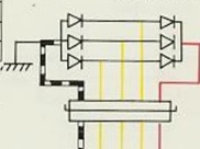
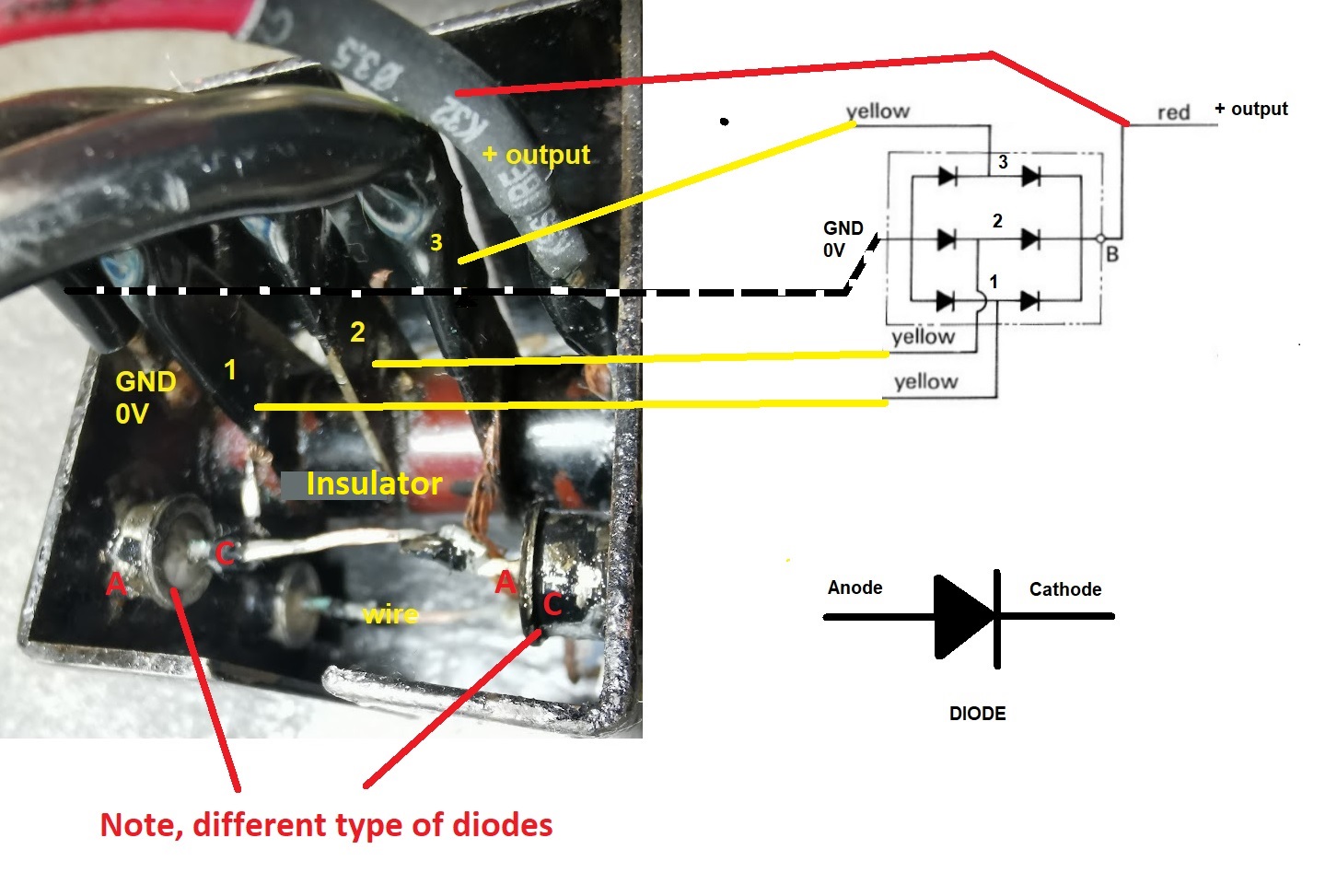
The figure above is a copy from the wiring diagram. It shows the 3-phase rectifier with three yellow wires as AC input and the plus (red wire) and GND(ground 0V black and white wire) as DC output. The wiring diagram also shows the housing (one of the heatsink) is grounded.
Note! I had a look on my GT750A model. An other type of rectifier (the smaller one) and the black and white GND wire is missing. All the grounding is done direct through the mounting bolt. Only four wires, three yellow and one red to the connector. A bit confusing, because the detailed wiring diagram for GT750 shows the GND wire, but not in the owners manual for GT750A. I assume it’s done different from 72-77 models.
GT750A version, no black & white GND wire.
If you are uncertain how the rectifier works with all 6 diodes, please review my previous post about the alternator for GT750 and GT380. There you will also find link to YouTube explaning how it all works.
The rectifier in the image above is from the J model. You can might find a different package on later models with smaller heatsink, but they all works in the same way.
You have six diodes, three with the anode connected to the case and three diodes with the cathode connected to the case.
Please note, the rectifier has the heatsink splitted in two parts. One is the pluss output ond the other one the minus output (GND) . If you scratch off the pain from the positive heatsink and by accident short the heatsink to GND you short all of the voltage to ground on your bike. Note! the heatsink is connected to plus, not the bolt. The image shows how the bolt going thrugh is insulated. I did a small mod using making the insulator in peek material to improve the design a little bit. The other part of the heatsink shall be grounded to GND according to the schematics. Mine was not and I’m not sure if it was wrong mounted or it is common not to do do. Anyhow, both options will work, but if not grounded all of the current to GND has to go through the black and wire to GND. I did it in my way and made better connection to GND from the heatsink.
Remember to remove paint to achieve a proper connection to GND.
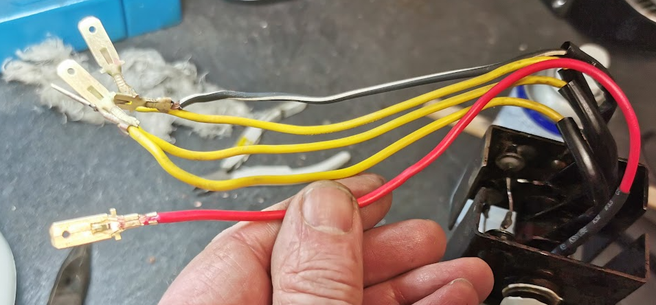
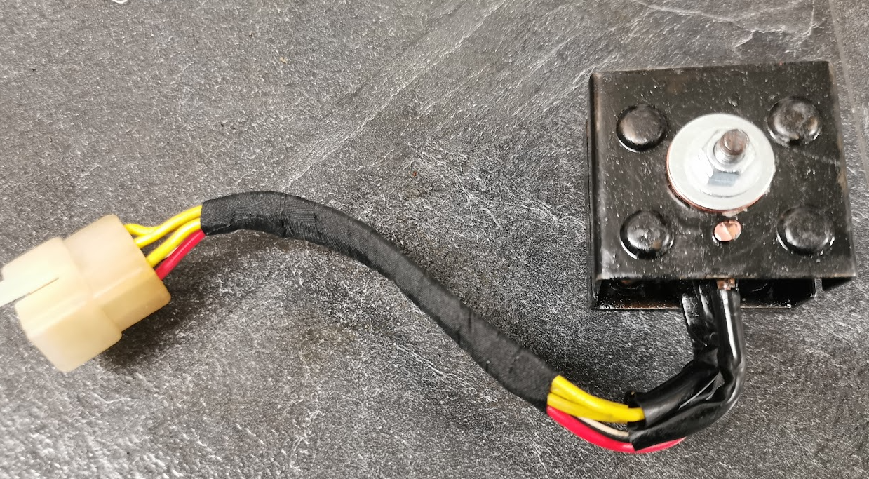
All of the connectors where polished and the red wire who was broken got replaced with a new wire and connector.
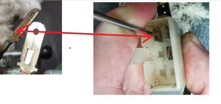
To remove the terminal from the connector, use a flat screw driver to bend the lip down and pull the terminal out from the rear side. Remember to bend the lip back to normal position when inserted.
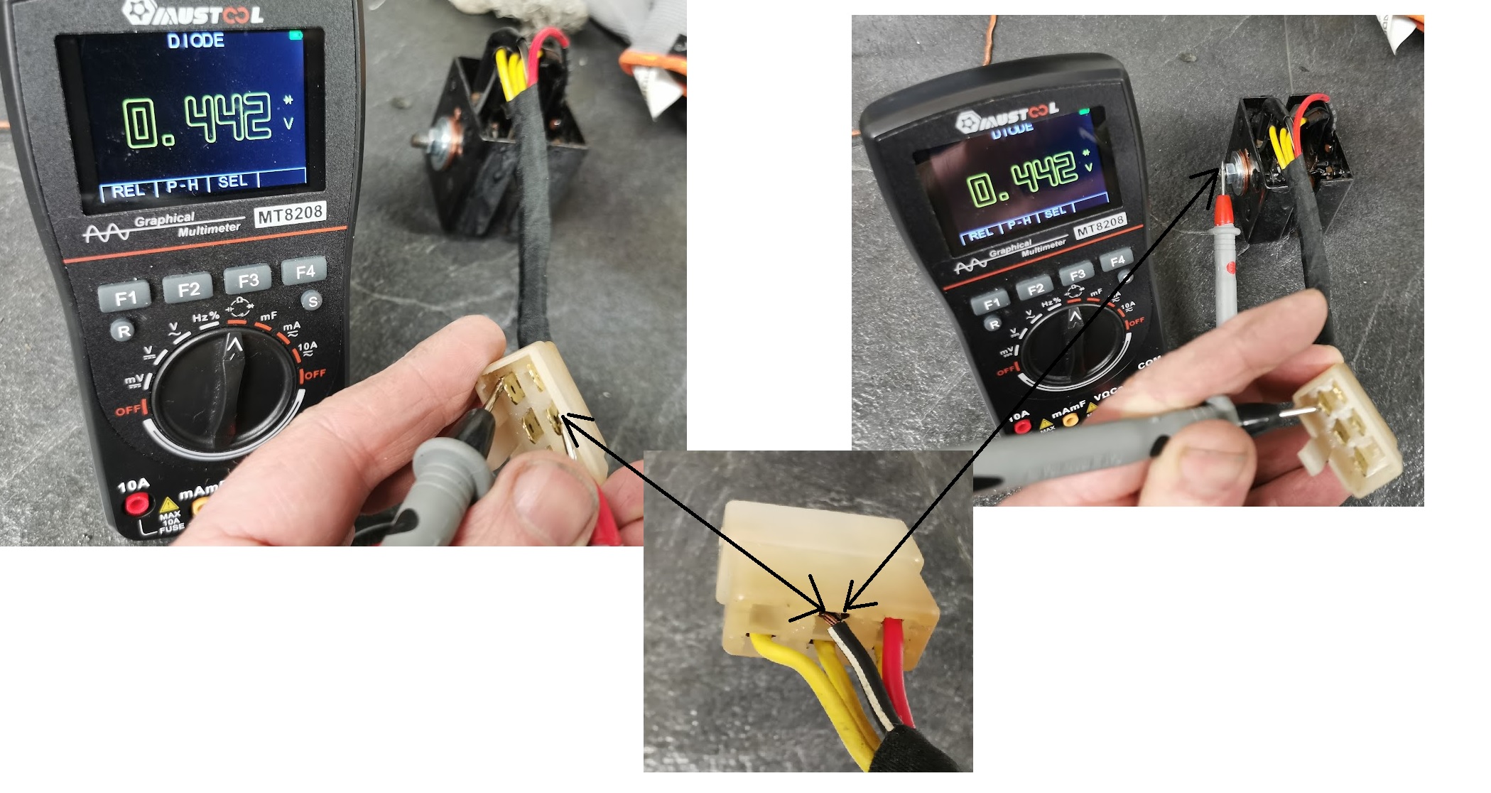
Diode testing:
When using a multimeter for testing, switch to diode testing and do the measurements. Positive terminal(red test lead) on the anode and negtive terminal (black test lead) on the cathode. Measure all six diodes, but keep track of anode and cathode. Since the three of the diodes have the anode to GND you can also measure to the heatsink insted of the black and white GND wire/treminal
The instruments shall give you a value for about 0,45V, and no voltage if you swap the terminals ( positive on cathode and negative on anode).
Measure all six diodes, but keep track of anode and cathode. Since the three of the diodes have the anode to GND you can also measure to the heatsink insted of the black and white GND wire/treminal.
If you don’t have any multimeter you can use a small 9V battery as input and and a test lamp at the output. When you swap the polarity on the 9V battery applying power to the yellow 3-phase input the lamp shuld still light, and do the same betwen all phases.
This post will be about the oil pump, for both the GT750 and GT380, old and new models.
The information below is my understanding based on testing and iformation given to me. If something is wrong, please let me know and I will updatate my blog.
Some basic informations:
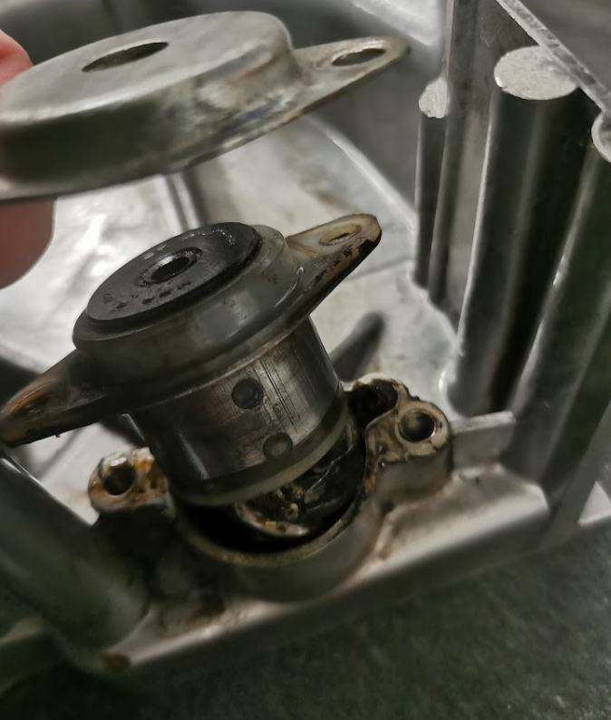
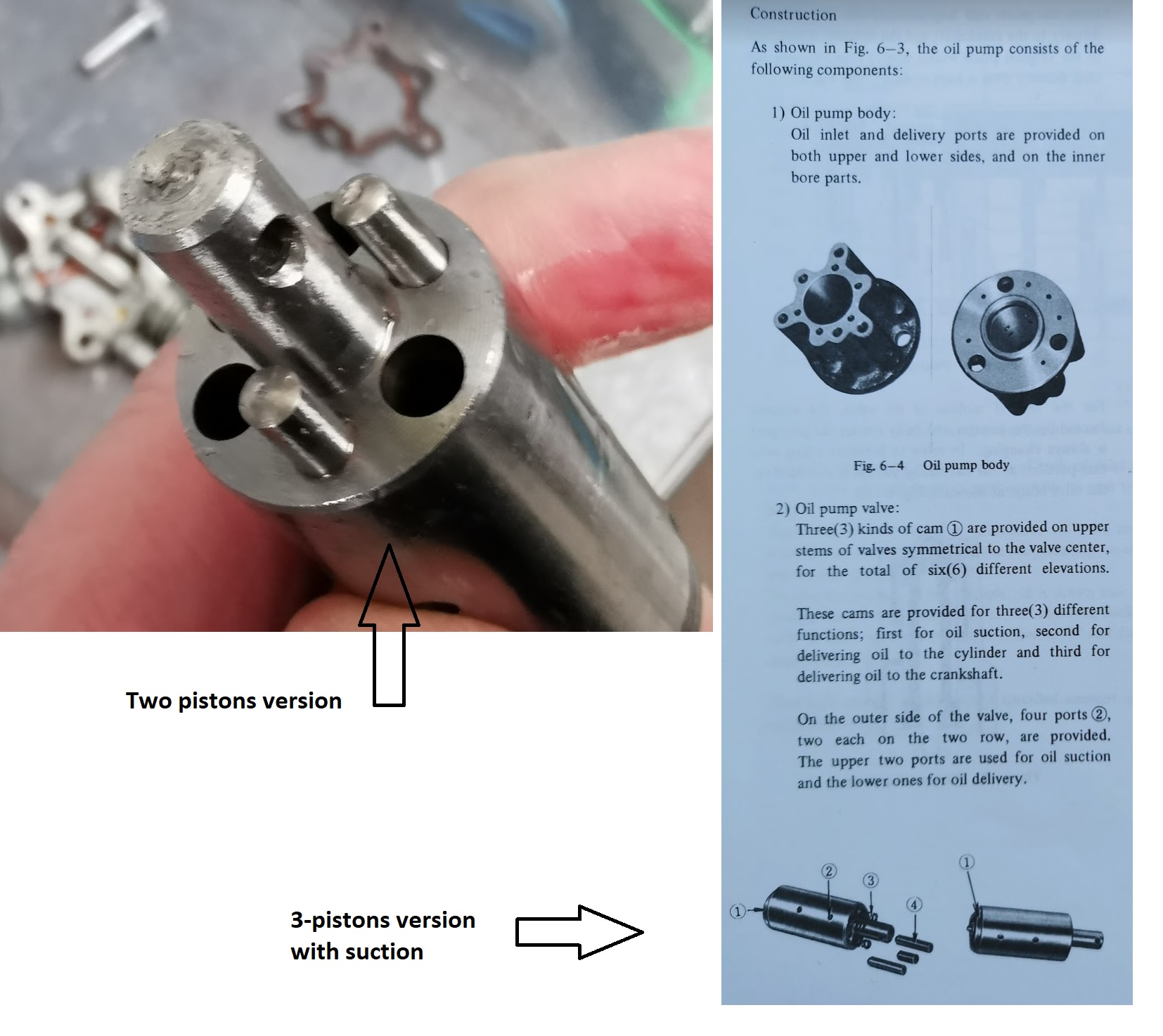
As the picture above shows we have an early model of the pump using one extra piston for suction. On later models the gravity from the oil tank above the thank do the job, and Suzuki decided to make it more simple with only two pistons.
Note! Never,ever go away from using the oil pump and only mix oil into the fuel, if so the crankshaft will not be lubericated.
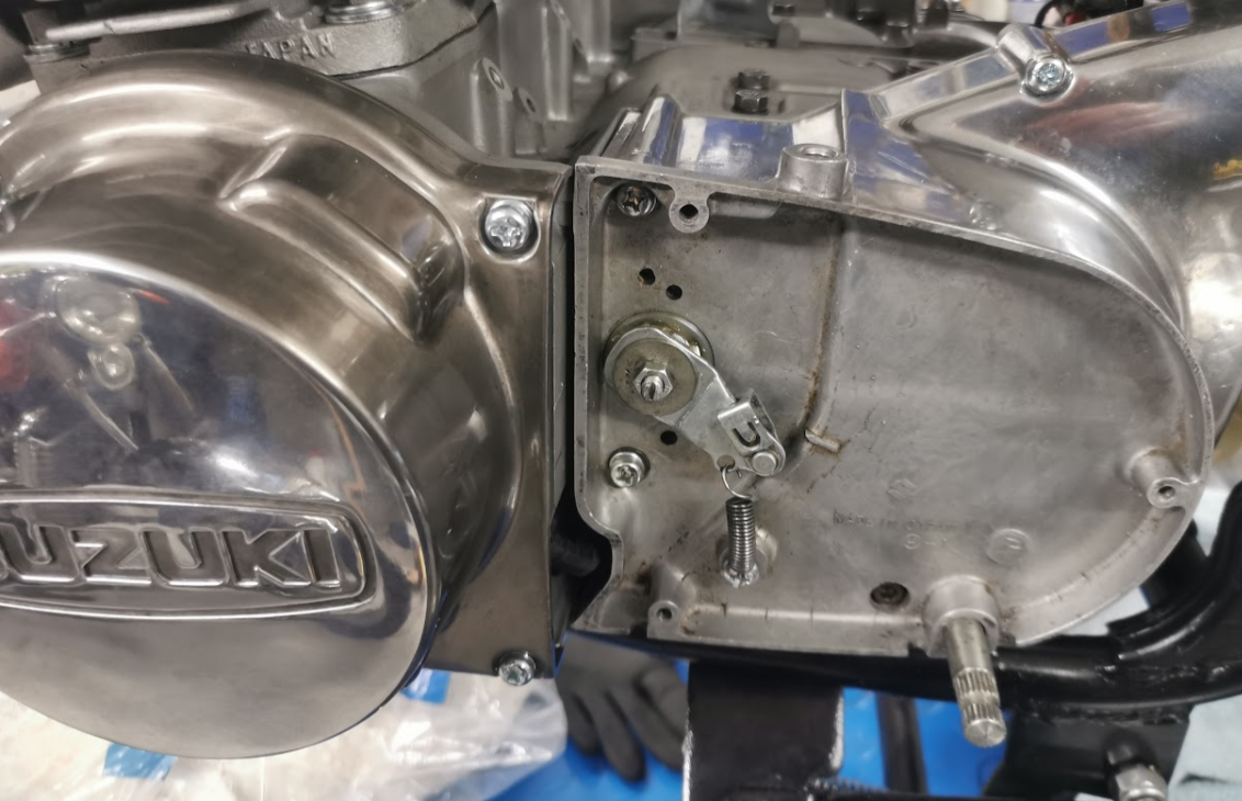
Are all pumps interchangeable ? Yes, all of the GT380 to GT750, old and later models, but there are some differences. Later models for GT750 using the vacuum carbs have a different arm connecting the throttle cable, see the picture below:
The punch mark and alignment marks are at different location (order) on J-K (GT750 models and all GT380 models) compare to the latest GT750 models. The alignment procedures are also differnt, see the picture above and the service manual.
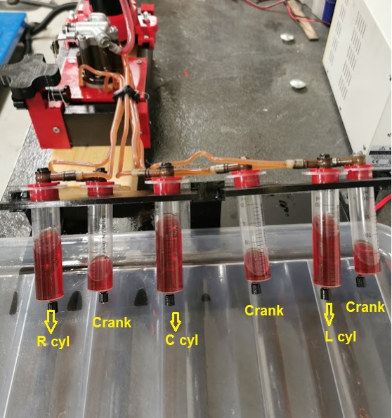
Test setup:
The speed of the pump is controlled by a DC motor and most of the parts are 3D-printed.
The shaft running the pump is made of brass and locked in position by two ball bearings.
Lesson learned after the testing:
At normal operation the cylinders get more oil compare to the crankshaft, but one important observation:
At the first punch mark there are almost no oil coming to the cylinders, only to the crank. On my test with two later models with only two pistons and no suctions, this was the case. A bit scary to watch. On the early model with three pistons and suctions I got a bit of oil to the pistons at the first punch mark as well, but no much. As soon as I increased the throttle it all worked as normal. Most of the oil to the cylinders and less to the crankshaft.
In the video below the pump is running between the first and second punch mark.
On my GT750 the oil consumption is close to 100ml per. 100 km, as it should be. In test above the rpm of the pump is 1hz ( 60 rpm) and refer to the engine that will be about 4000 rpm. The consumption from the test looks very much the same as I see on my GT750, but the 3-piston pump with suction gives a bit more.
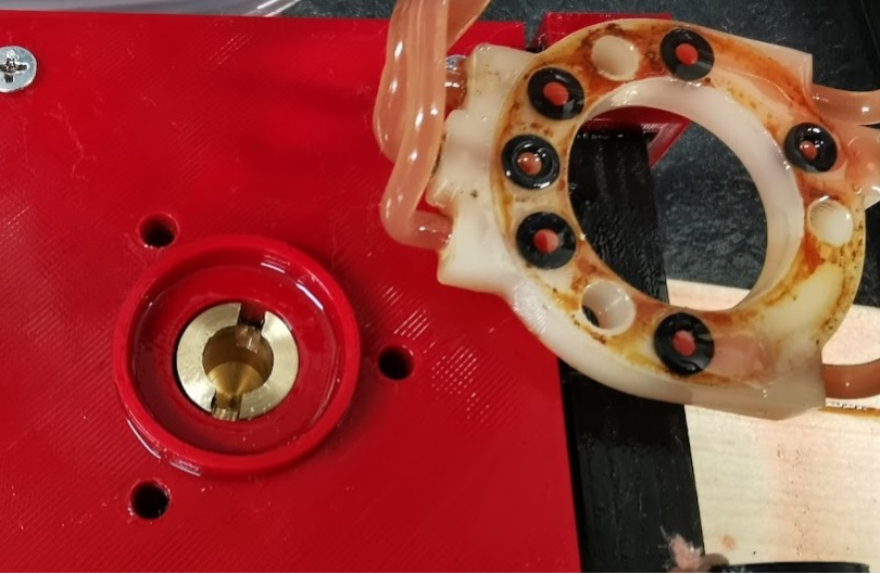
Gasket:
I ordered new gasket from E-bay, but to start the testing I made my own by scanning the old one and cut new with my laser cutter:
Seems to work fine. Since I have paid the money for new ones, I might swap the gaskets when they arrives.
Note: Points or breakers are the same. I usually refer to the breakers calling them points.
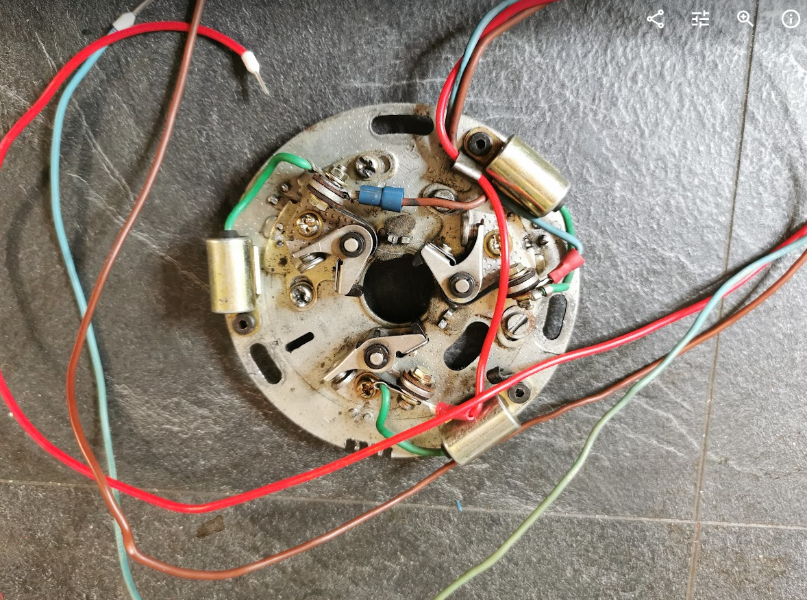
As mention before, my GT380J project was in a horrible state when I bought it. No exceptions when it comes to the electronics. Wrong connectors and terminals. Wrong color codes on many of the wires. The wiring for the contact breaker was a mess too and I had to make it all new according to the wiring diragram.
This is how it was, wrong wire colors, wrong type of screws, and missing connector.
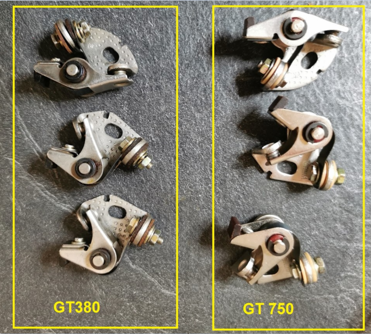
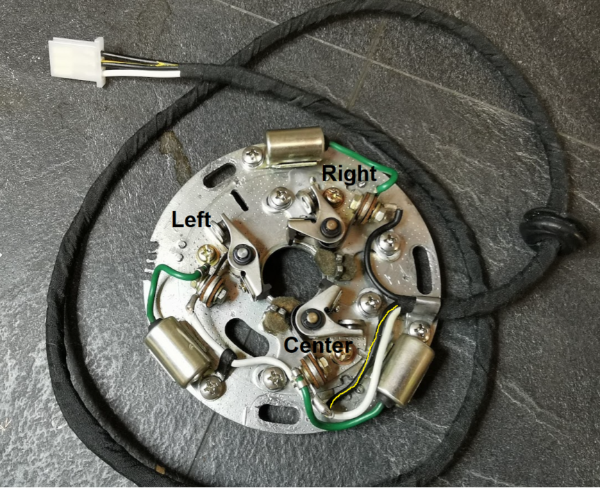
By the way, be aware of the difference from GT750 to GT380. Since the points are located on the right side of the bike on GT380 and left side on GT750, they have to be mirrored. Don’t buy the wrong ones.
The left point is locked direct to the main plate and has therefore a different shape compare to the center and right point.
Where to start ? I found this picture below on E-bay and it looks alright compare to the wiring diagram.
The picture also gave me some idea of the cable length.
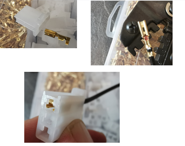
Connector:
I bought a kit from China with a lot of connectors and terminals making it possible to fit the corresponding connector in the main wiring harness.
Connection to main wiring:
Note, on the GT380 the connector goes directly to the main wiring, not through the connector plate as you see on the GT750.
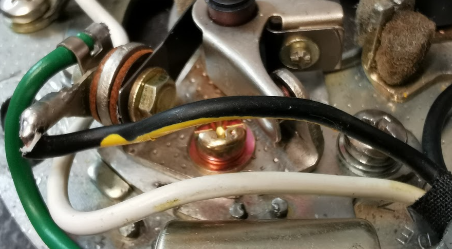
I was not able to find a black wire with yellow stripe, and as you see, I painted the yellow stripe to get the color code correct.
Left point: White
Center point: Black and yellow
Right point: Black
How to fit the contact breaker and adjust the timing will come in a later post.
You will also find a colorized diagram in the categories Electronics \Wiring diagram. The one above is a copy from the J model owner’s manual (1972 J model). The black/white version above is perhaps more easy to read, and is unique for the J (and K I think)
This is a trial assembly of the side cover, just to see if it all fits. The covers on top of the engine are also loose. Will be removed before I load the engine into the frame. The crank lock nut has to be tighten after the engine is bolted into the frame. I should have tighten the nut before the cylinders were mounted and blocked the rods when doing so, but now it’s to late. Will therefore lock the front sprocket when tightening the nut. Difficult to be done before the engine is bolted in the frame.