Browse Author: tore@grenasberg.no

Gauges

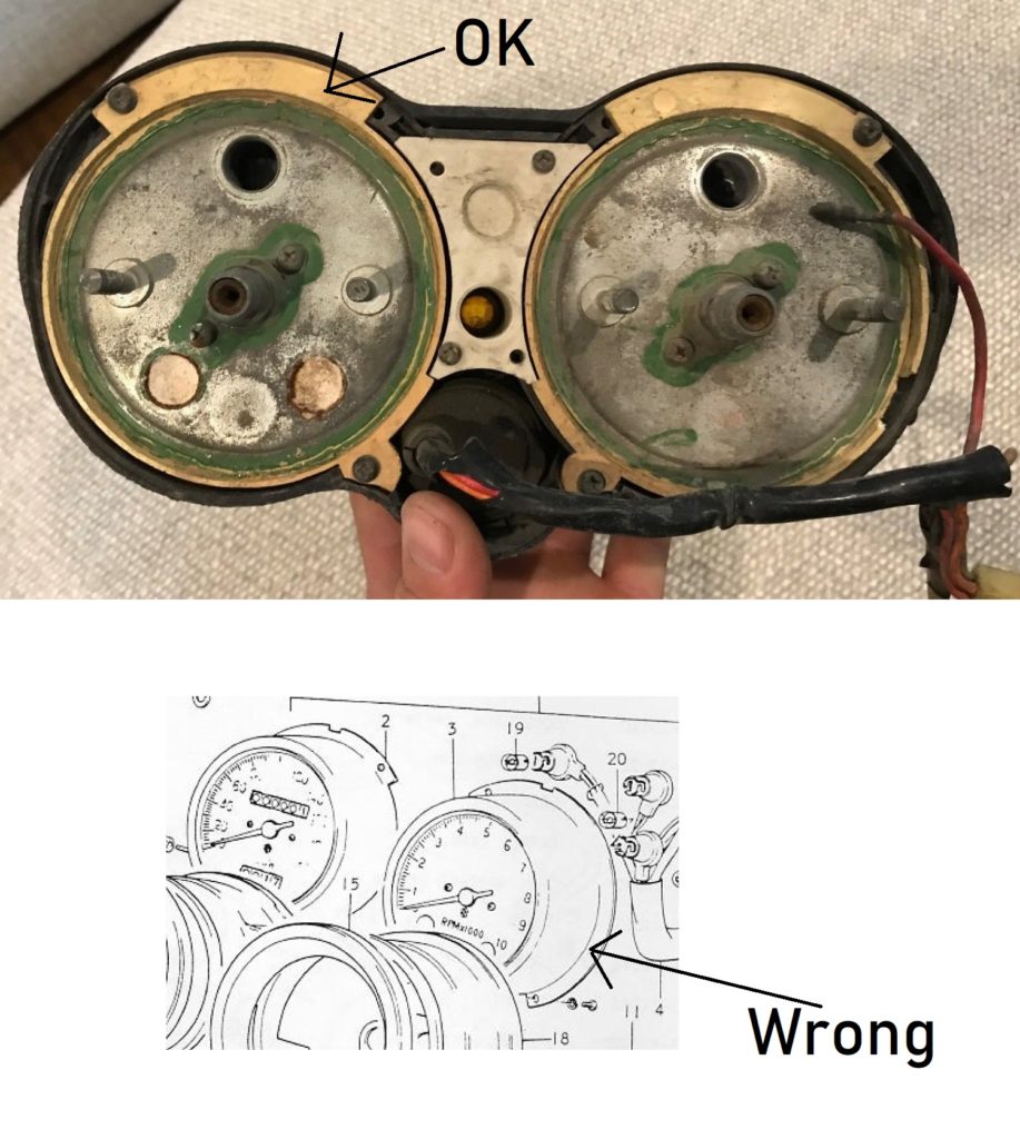
The outer housing for the gauges was a disaster. Previous owner had cut off a big piece to get space for an unoriginal ignition switch. Was lucky and got a new housing in a good condition.

The face of the speedometer looks nice. The tacho face has dents and is quite worn.

The needle is also different on the clocks. The 72 model should have chrome in the middle, not white as on the tachometer. The speedometer is all OK.

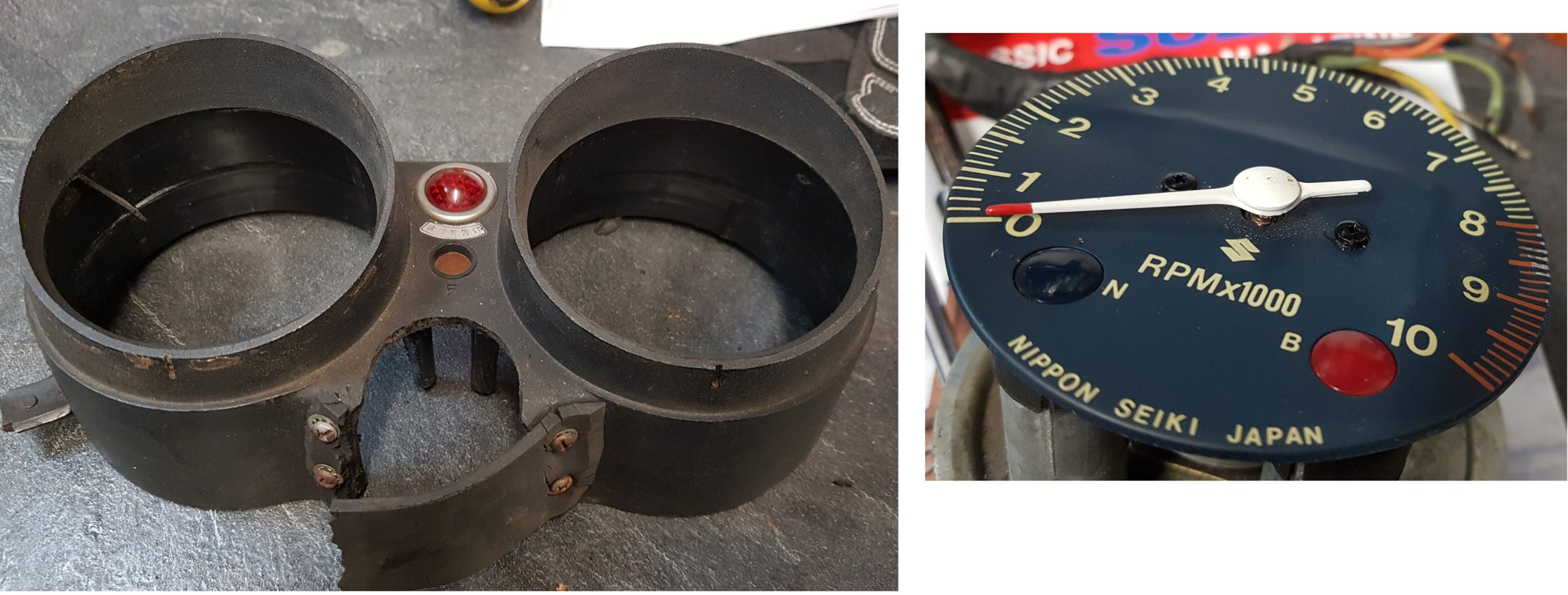
In addition, both inner housings are in bad shape. Cracks and missing parts.

Can replace it all, but not easy to get 48 years old gauges in a good condition. I also want keep it as original as possible when it comes to the look of it. Therefore I will not mount later models. And I have always wanted to restore gauges and this is the perfect time to do it.

New tachometer face:

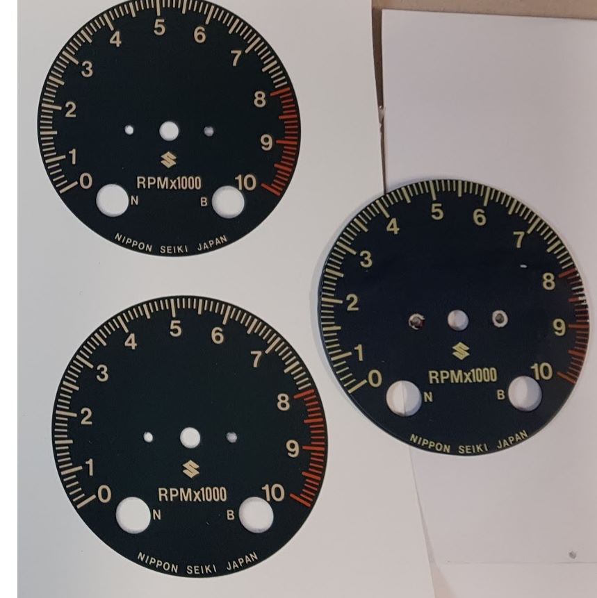
The one to right is the damaged one. I scanned the tachometer face and got it edited in SW on my PC. Handed the file over to a printing service and got six new prints as stickers. I’m very pleased with the results and the colour looks to be spot on.

Will make a new aluminium disk without dents.

Inner housing:

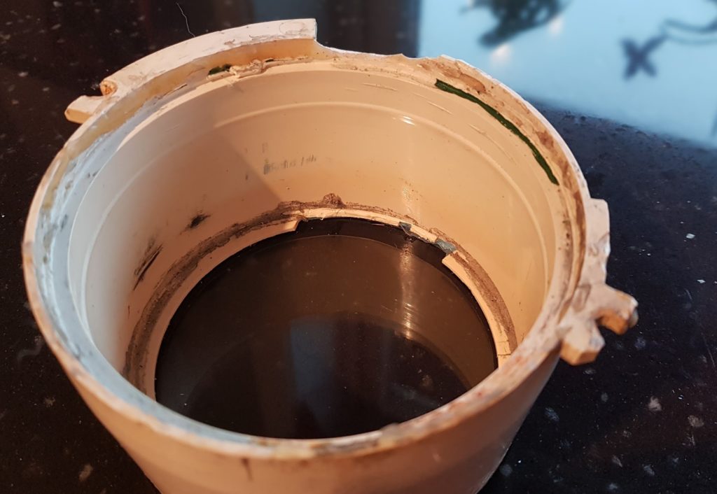
The image above is for the tachometer and the one for the speedometer is just as bad. What to do? Hmm, lets give it a try. I can draw new ones and get them 3D printed.

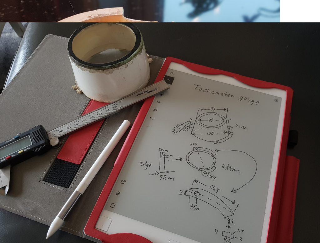
Sketching up the measurements on my sketching pad and will try to do the design in Autodesk Fusion 360.

But first I have to learn how to use the SW, Fusion 360 is all new to me.

A simple trial design:

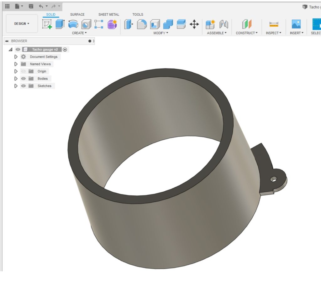
This was fun. Pretty sure I will get it done, and it will be good as new. The image above is not correct, only a test piece. I will post the final files on my blog if anyone wants to download and print their own.

Not sure when, but it will for sure be done if I get this right. The face of the tachometer will also be uploaded.

Next day:

The learning curve of Fusion 360 was not steep, quite easy after few hours of watching YouTube and I did some trial design.

A bit more tricky to figure out the correct measurements from the worn clock housings I have. The drawing from the K parts manual can’t be correct, will never fit.

After studying Ebay and watched carefully on photos from J/K types, this must be the correct one. Fits well comparing against my broken parts.

Image from Ebay:

Think I got it, the first design of the Tachometer house is done. I left out some of the profiles since I don’t see any need for them.

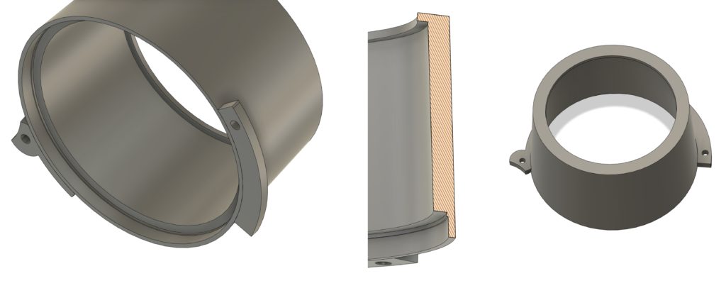
Hope to get the first trial print at work in about two weeks time. Not sure about the quality, but later on I will have access to a much better printer and can use white filament as well. The first one has to be painted white. I’m so exited to see the result πŸ™‚ One week of vacation now before I continue with any 3D printing.

Cylinders

Got a surprise when starting to assemble the cylinders. Some of the 8mm stud bolts where missing and had been replaced with 6mm bolts.

This is what happens when working on a 48 years old project. Previous owners must have been too careless while mounting the pipes, as usually, too much torque and the threads are gone. A bit odd fix. They have used 6mm insterts in three places. I can’t have a mix of 8mm stud bolts and 6mm bolts. Not on a bike as stunning as this πŸ™‚ So, what to do ?

Having a lathe is a big advantage while doing overhaul on a bike, a worn out bike.

Made four new studs. One original with 8mm threads in both ends and three with 8 and 6mm. One of the 6mm came out a bit bent, will fix it.

Done ! πŸ™‚

Threads :

I did a refresh of the threads on both the bolts and the nuts. Not to get a surprise during the mounting.

10mmx1,25mm fine pitch threads.

Piston rings:

Before mounting the cylinder, make sure the gap in the piston ring is above the pin located in the groove.

Mounting of the cylinders:

Mount the gaskets and start with the cylinder in the middle. Apply some 2-stroke oil and slide the cylinder down. Don’t forget about the position of the piston ring to close above the little pin. Should slide easy down, not needed to use any force.

The last one and it’s done.

I was not able to find any torque settings for the cylindres, only for the cylinder head. Since there is no space to use torque wrench on the nuts I used the tools I had and fasten using sensible amount of torque πŸ™‚

SRIS:

All of the cylinders have plugged SRIS outlets. I will therefore mount the case without the SRIS valve no.17. Dont’ see any issues of burning a bit more smoke at startup.

Pistons

Time to assemble the pistons. Bought a kit with piston, circlip, bearing and the pin.

The procedure is wery much the same as shown in my GT750 post some years ago:

GT750 post:

Please we aware of some differences: For the GT 380 all three pistons are identical. There are no washer in the piston as on the latest GT750 models, only the circlip to keep the pin in position.

Pictures from the GT380:

Remember to move the circlip gap at the opposite position to the groove, picture 3-4.

Insert the last circlip and you are done (picture 6 )

Done πŸ™‚

Fork headache

Almost a year after last time I looked into this I’m still a bit confused. Difficult to figure out, but I think I’m on the right track now.

Not easy to find parts manual for the J-model. Manuals claiming to do so always starts with the drawings from the K-model. And if I find drawings from the early J version, they are without any part no.

After a lot of research I think I got it. Look at the green box for the J model. No 4 and 14 are both oil seals. For the K-model no 15 is the oil seal and 14 is a ring above the oil seal to lock the seal in position before the no 13 clip.

And why is no 24 part of the drawing, don’t see the need for a dust seal, or if it can be fitted underneath the no.19 boot ?

Anyhow, I will order parts according to the K-model since it’s an upgrade from the J. All other parts seems to be the same.

Next headache:

Can’t use the photos I took while dismounting the fork. It’s a mess from previous owners. No 9, the valve damper was mounted upside down. No 11 and 12 had swapped placements. The order of the parts at the picture above shuld now be correct.

Was lucky to get hold of a brand new outer tube and a new inner tube. In addition I bought a used inner tube in a good condition. I can therefore replace both of the old inner tubes.

Final headache:

The tube at the picture above, screwed down into the bottom of the outer tube can’t be seen on any drawing. From the L-model and off, the tube is part of the drawings, but an other type tube. From the L models and off, there is a piston ring in nylon mounted between the tube and the spring. I “guess” I don’t have to fit that part into the J/ K fork.

First parts to be mounted after closing the crankcase

Rear drive shaft

The parts above are for the rear drive shaft. Remember to add thread lock on the screws holding the no 33 retainer

Oil pump and tacho drive

Mount the gear for the axle driving the oil pump and the tacho drive.

Crankshaft gears

Have to buy a new lock washer before I torque the nut.

Crankshaft set plate

Apply thread lock on the screws.

Clutch

A new lock washer must be bought here as well. Don’t mix the thrust washers, they are different.

Case closed

The upper part of the crankcase was glued using Loctite 574 as sealing. In the same way as I did on my GT750.

The Loctite 574 does not harden in air, only under pressure. A very common type of sealing for all type of crankcase.

Closing the crankcase:

All bolts are labeled with numbers. If you look close at the image you will see the number 25 is written into the case, just below the yellow arrow. That’s the order of the torque settings. If the crankcase is clean it’s easy to see the numbers. Mount all the bolt on the top side but don’t thight too much at this point. Make sure the crank is moving freely before turning the case onto the other side.

Since I have stored the bolts on a picture glued to a carton It’s easy to pick the right bolts with the correct length. All of them have been cleaned and polished. The S mark indicate bolts with more strenghts than bolts without the lable. The S bolts are for GT models but not for GS models. The GS bikes have labels with 7 on, not S. I found only GS bolts mounted on a spare crankase from a late GT model, 76-77. Not sure if that was original from the Suzuki factory or if someone had swapped them all. On my GT380 engine I mounted all the S-bolts I had except from a couple of 7-bolts.

Torque order:

Bottom case:

In addition to my picture above you will find the torque order in the manual and it’s written onto the case.

Top case:

From the manual:


In Nm:

8 mm bolts: 20 Nm

6 mm bolts: 13Nm

DONE:

Paintwork

My nephew Thomas is doing all the paintwork. A 100% professional work, a stunning high quality job has been done.

The colour is a bit lighter in real compare to the pictures. It’s not original Suzuki J colour, but this is the one I want to have. I’m so pleased with the choice.
Have double up of both fuel tanks and side covers.

Crankshaft

Before mounting the crankshaft, make sure the C-ring is in place in the groove, see the yellow arrow. There is only one to be fitted.

The grooves shown from the red arrows are meant to grab the oil seals. When I got my crankshaft back from overhaul the seals had no marks to fit into the grooves. The old ones had. Don’t know why but they should be original Suzuki seals according to the workshop. Probably a design change on later models.

Align the studds into the grooves as shown on the pic.

The seals should be moved into the bearings, see the red arrows.

A bit of 2 stroke oil will not harm.

Kickstarter

Hmm, was not able to align the punch marks as described in the workshop manual.

If I follow the procedure, the spring on image 3 is way too loose. If I turn it all the way around it will be too tight. Got advice from guys on FB and will ignore the punch marks. Mounted as on pic 1 and after the case is closed I will rewind the ratchet wheel 3/4 of a turn to give the correct tension. The rachet wheel is outside the crank case and can easely be adjusted. By the way, the punch marks were also wrong on my GT750 engine.

Don’t forget to mount the gears for the oil pump and tachometer:

Gear assembly

After repairing the crankcase :

I mounted all the gears before I spotted the damages caused by the lock pins. See my previous post explaining the issue.

http://mc.grenasberg.no/2019/12/30/lock-pin-repair/

I therefore had to remove it all and assemble the gears once more after repairing the crankcase.

Step 1, see the previous post, GT380 Gear shifting.

http://mc.grenasberg.no/2019/08/05/gt380-gear-shifting/

For a detailed view on how to mount the gear shifting mechanism, see how it’s done for the GT750. It’s very much the same:

http://mc.grenasberg.no/2016/02/21/gear-shifting/

One difference is of course the number of gears. Five on GT750 and six on GT380.Β  In addition, the CAM stopper is not mounted from the bottom side of the crankcase as it’s done on the GT750.

Step 2:

Mount the pin and spring:

Step 3:

Mounting the forks:

As always on my blog, click on the images for a more detailed view.

Step 4:

Don’t use thread lock on the screws at this point. Wait until you have checked all the functions of the gears.


Step 5, gears.

Front axleΒ 

Running smooth and nice.

Rear axle:


Checking the shifting of all six gears:

Added labels on both axles to easy count the ratio of the gear shifting. It all looks good πŸ™‚

No issues as I can see while shifting the gears up and down. The no 1 gear runs a bit tight compare to the rest. Don’t think i will cause any problems. I will open up the spare engine and check to verify its condition and compare the gear shifting against this one, but not today.

The outer C-ring is missing on the rear gear axle. Will borrow one from the spare engine later on.