Browse Author: tore@grenasberg.no

Lock pin repair

After months of doing nothing on the GT380 I’m now back on track. This fall has been very busy and I had to focus all on work and not much spare time to invest on my GT380. Hopefully it will be better the following winter and spring.

Two weeks of Christmas vacation has been good and I was able to get some steps further on the project, but then…..I spotted a disaster.


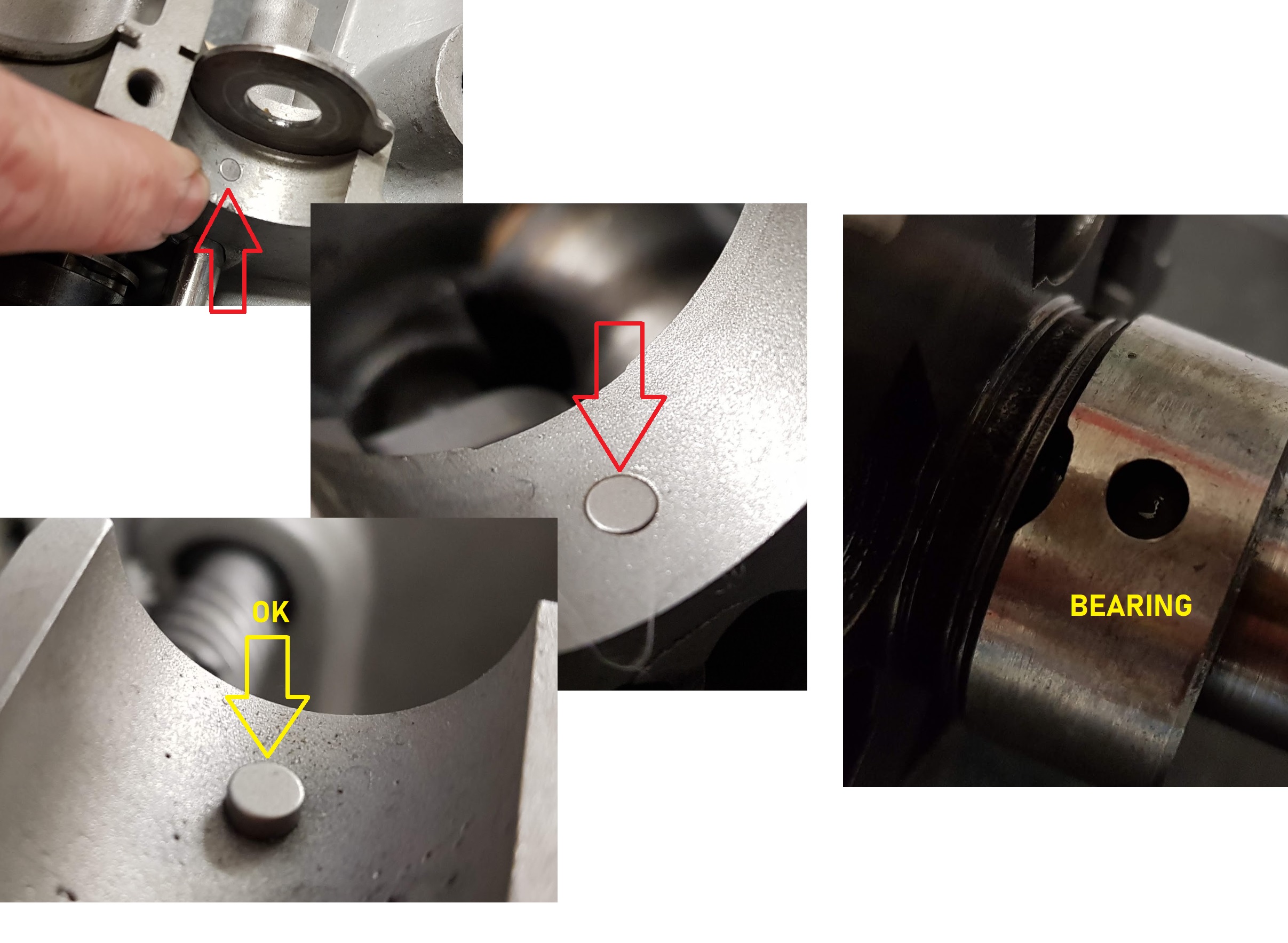
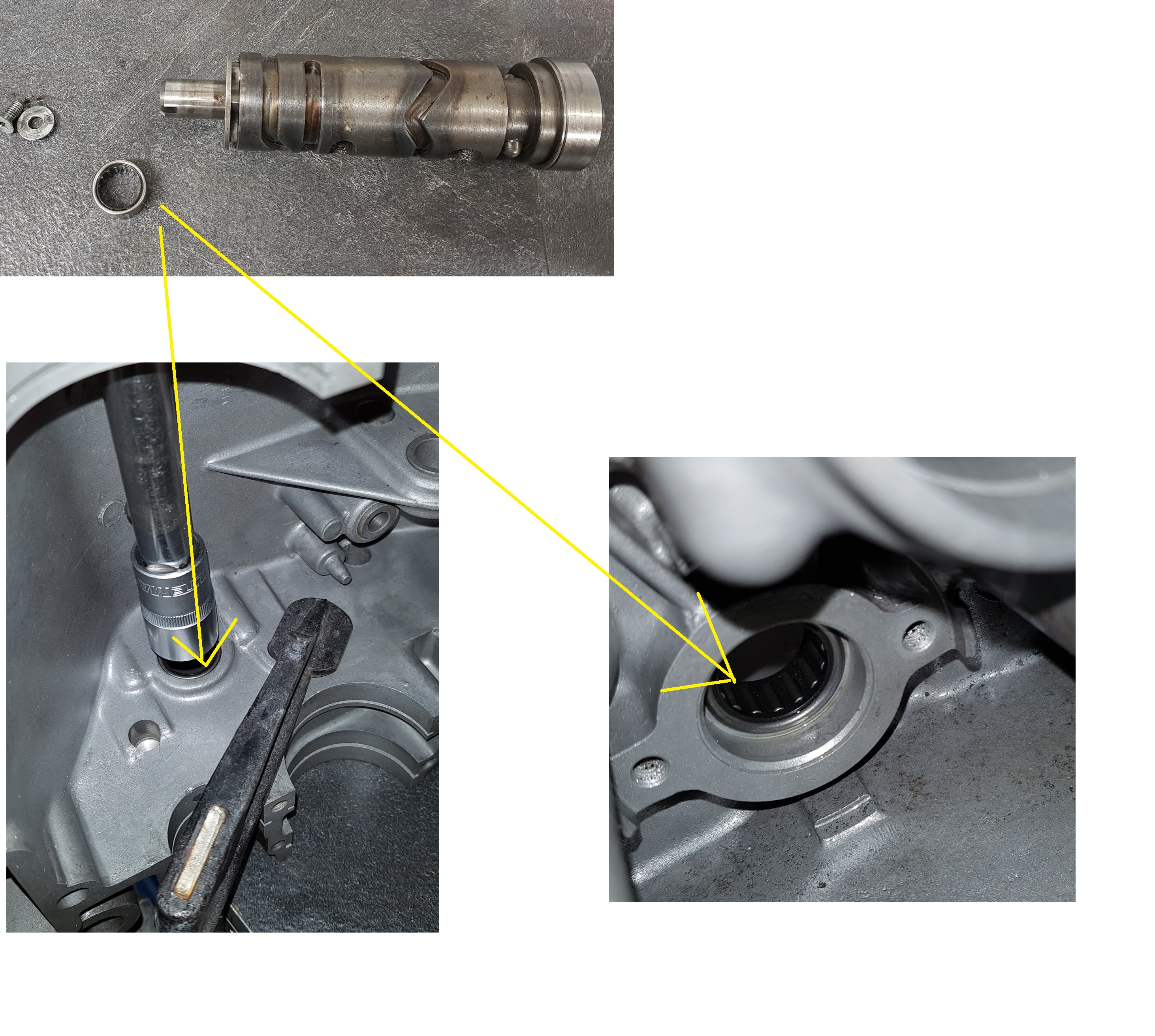
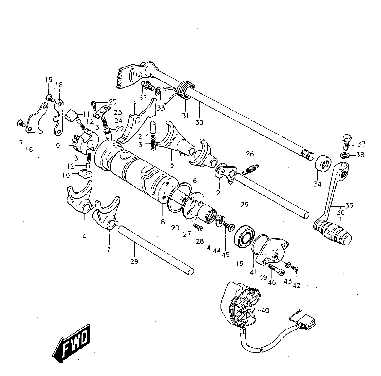
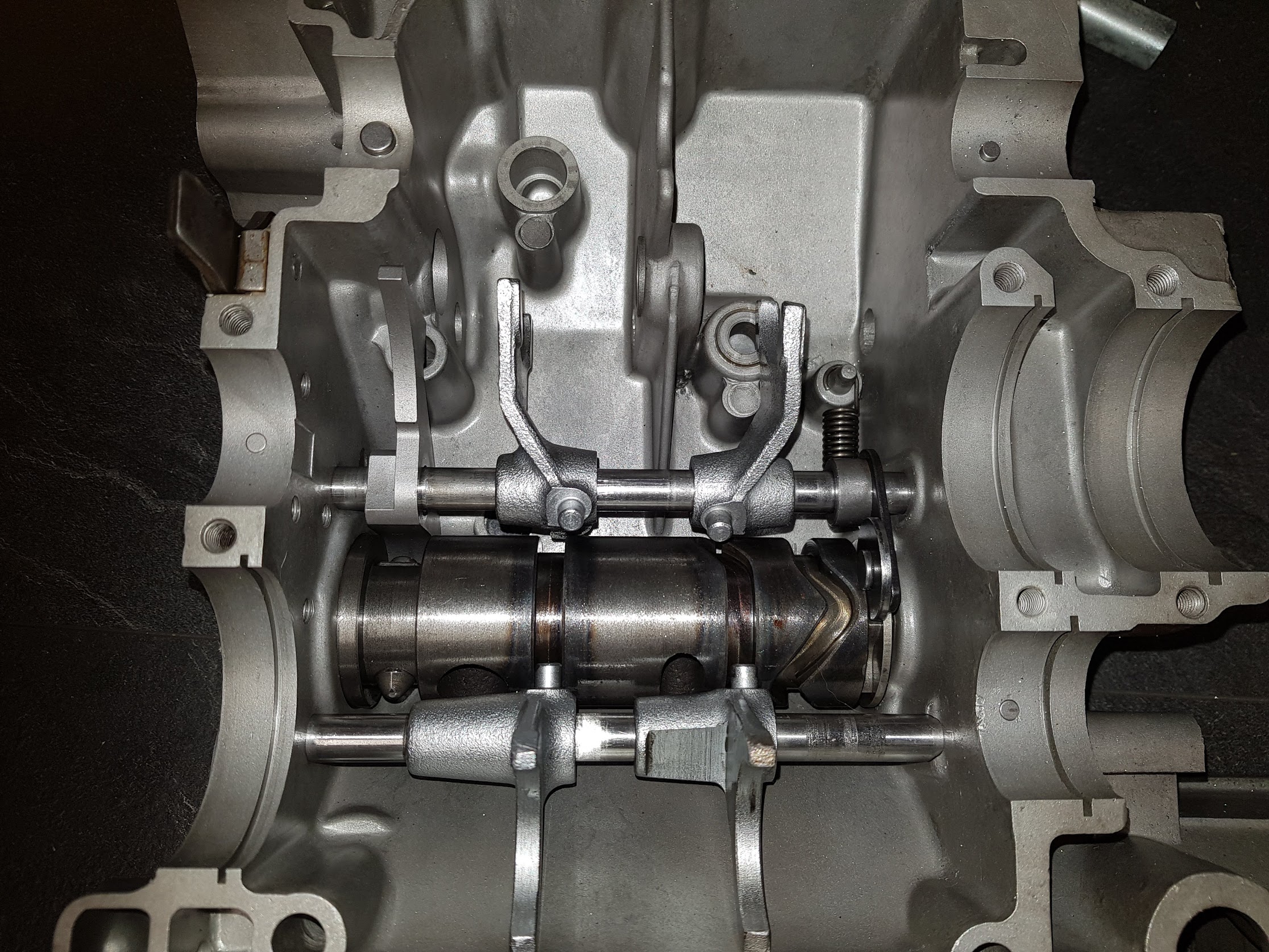
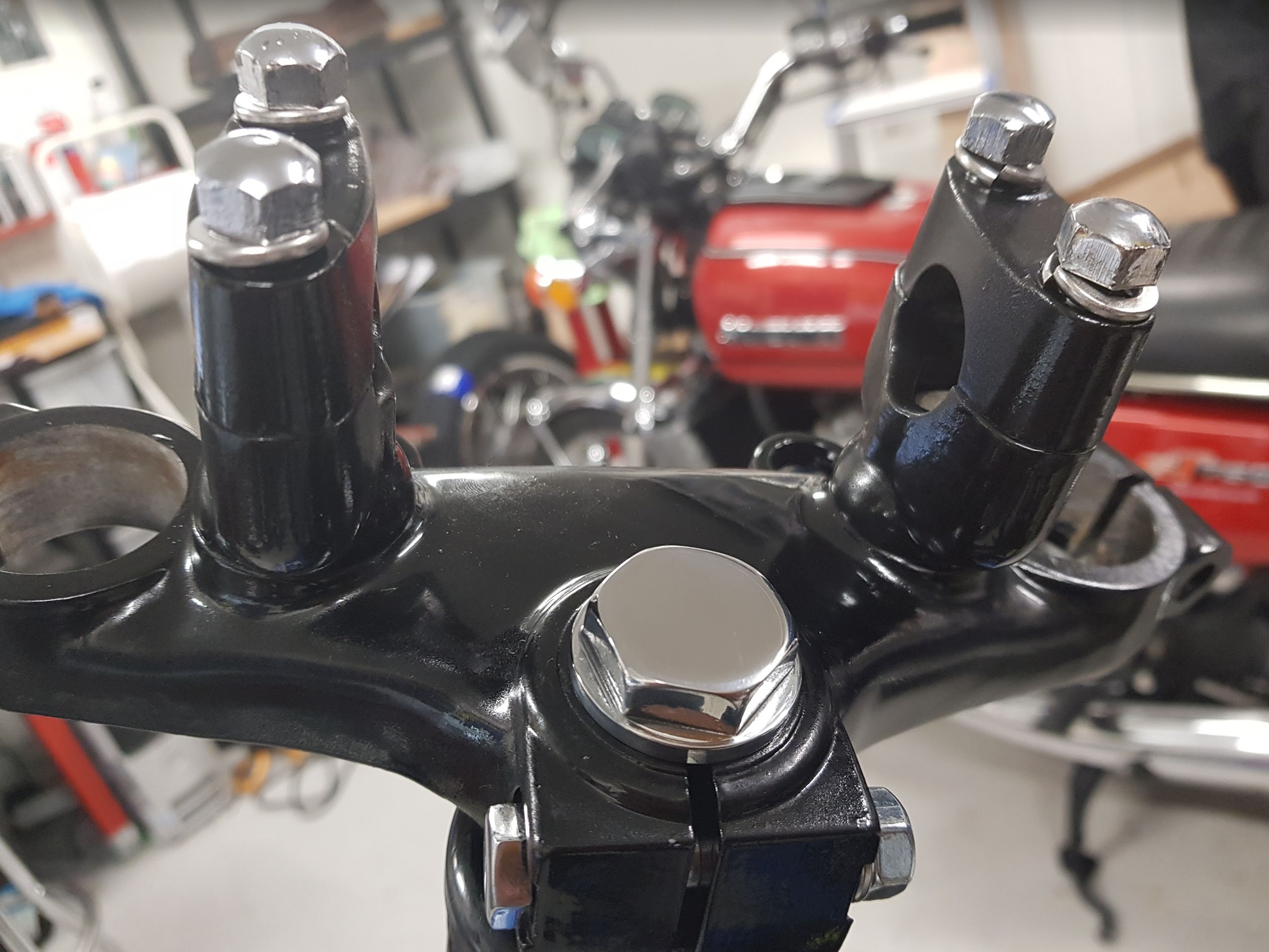
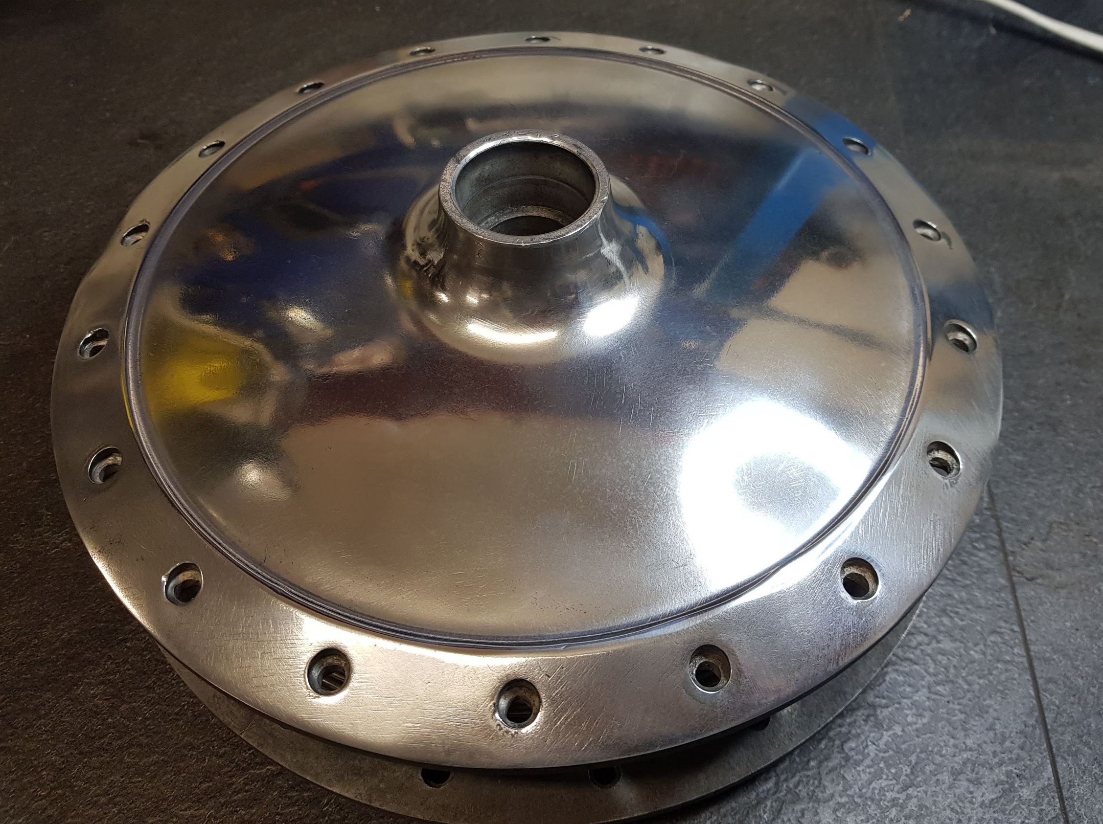
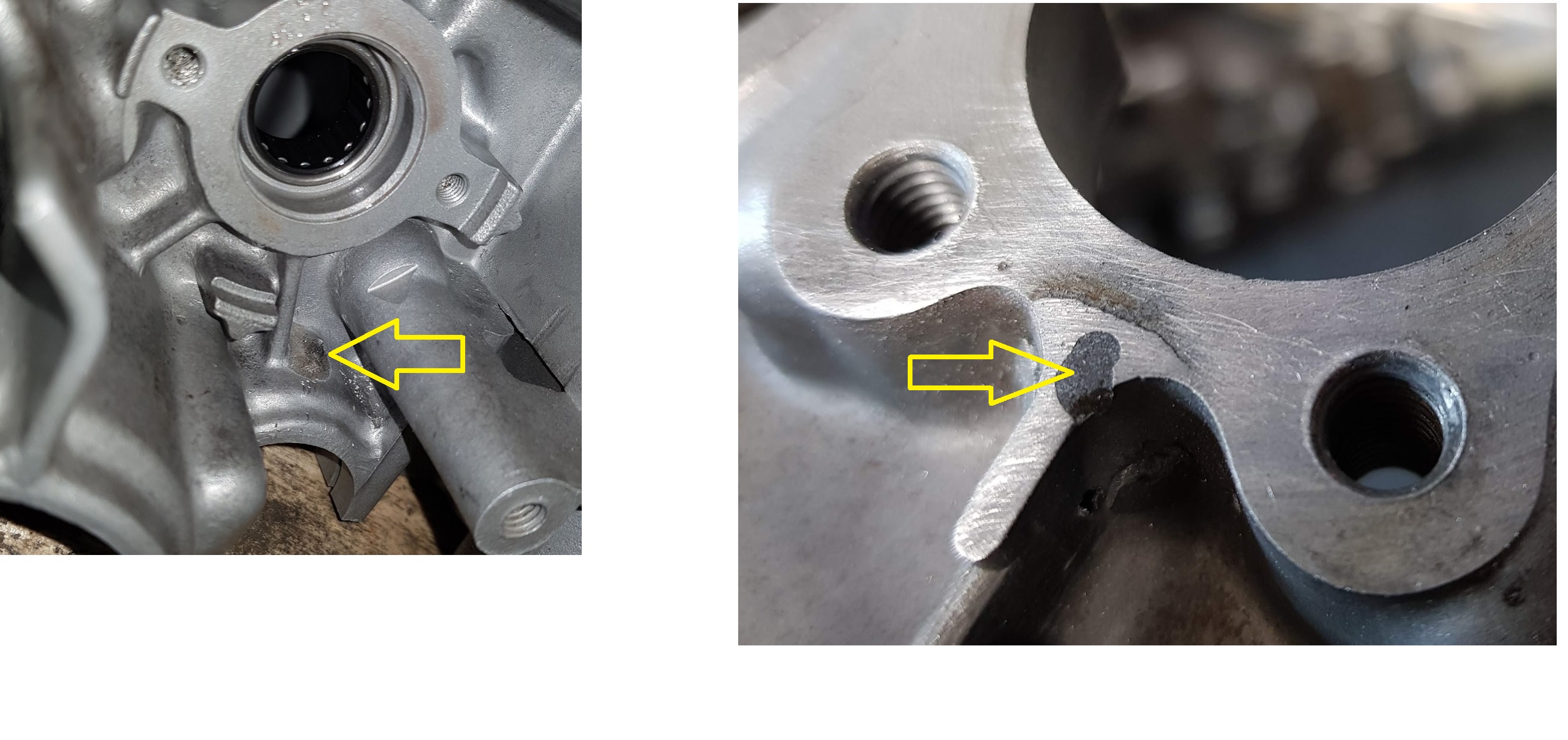
Two of the lock pins holding the bearings at the gear shaft in place were squeezed all the way down into the crankcase. I should have spotted this at a previous stage, but what now. Is it game over. Do I have to get a new case ? Cracks on the other sides as well due to the brutal force into the aluminum.

Previous owner must have done this without thinking properly before assembling the engine. And on both gear axles…This is what happens when you rush into unknown stuff without taking the time needed to think twice and think it through.

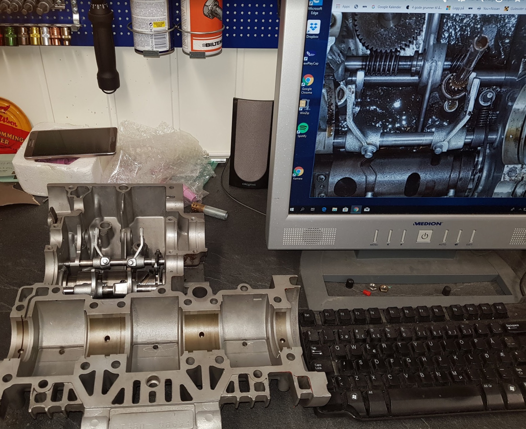
I have a spare engine I can use,  but consider all the work I had put into this it’s worth giving it a try to fix this one. And if it works I will still have two GT380 engines.  This is how i did it :
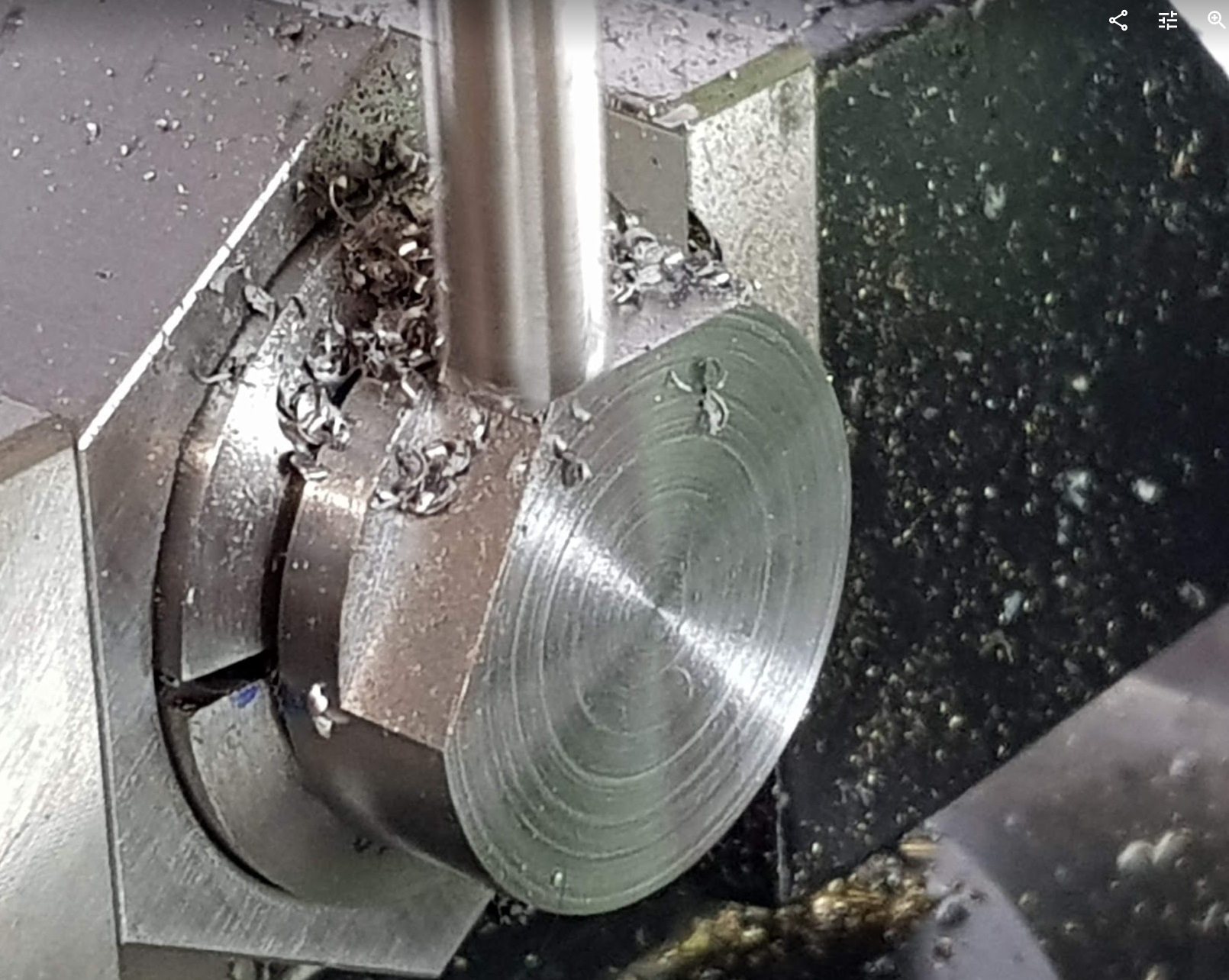
Step 1:

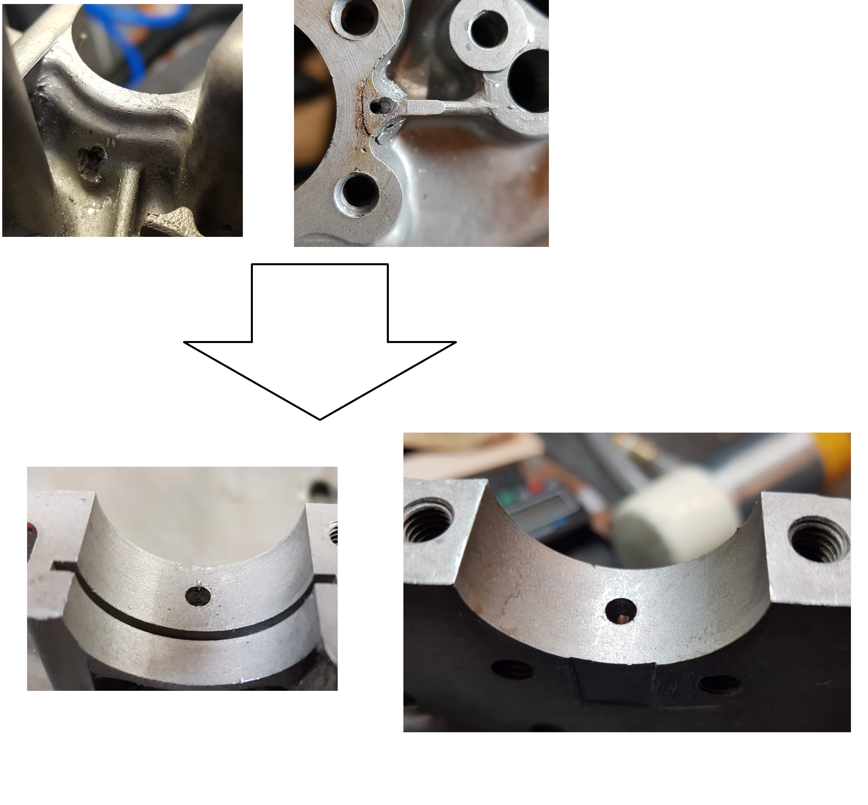
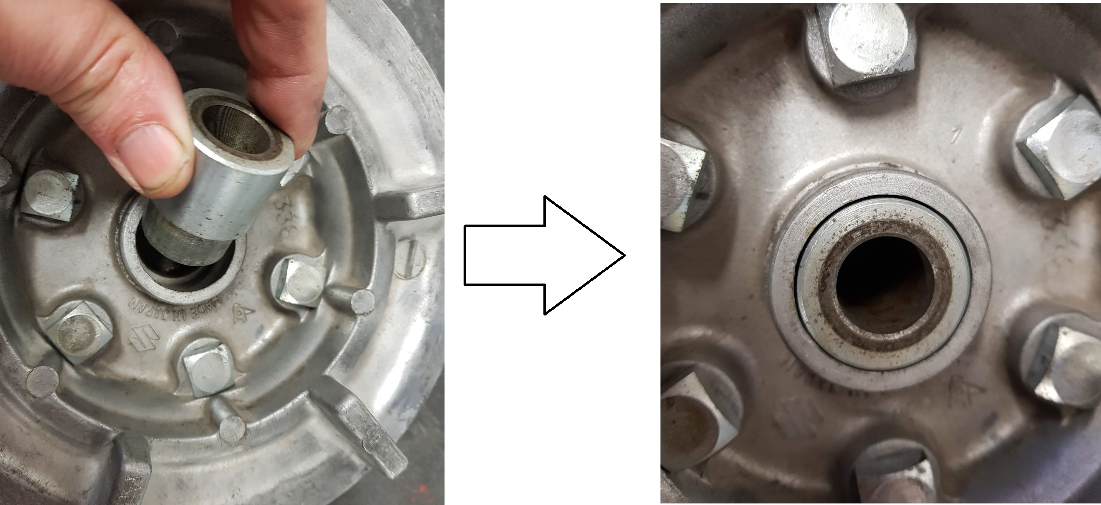
Drilled and milled holes at the rear side and was able to push the pins out.
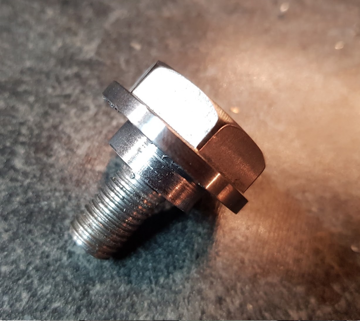
Step 2:

Drilled 2,5mm hole from the top side. Threaded 3mm and inserted a set screw and adjusted to the correct depth.
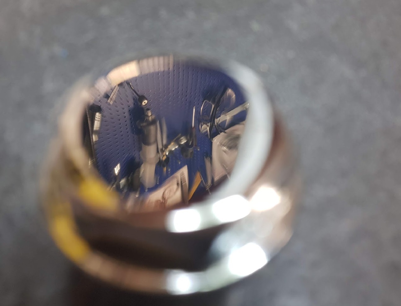
Step 3:

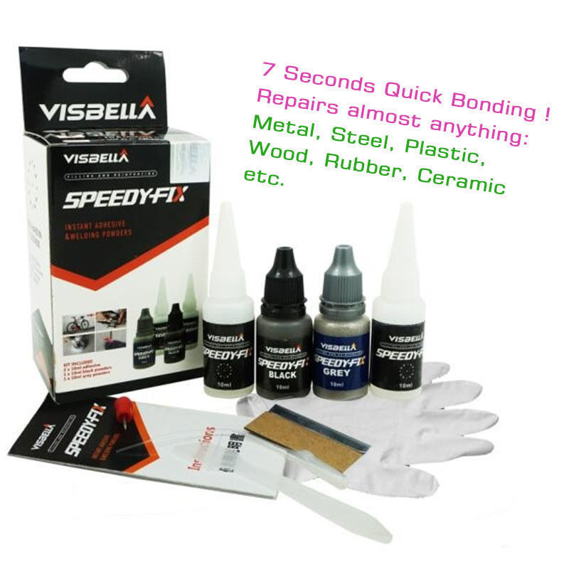
Gluing using Speedy-Fix

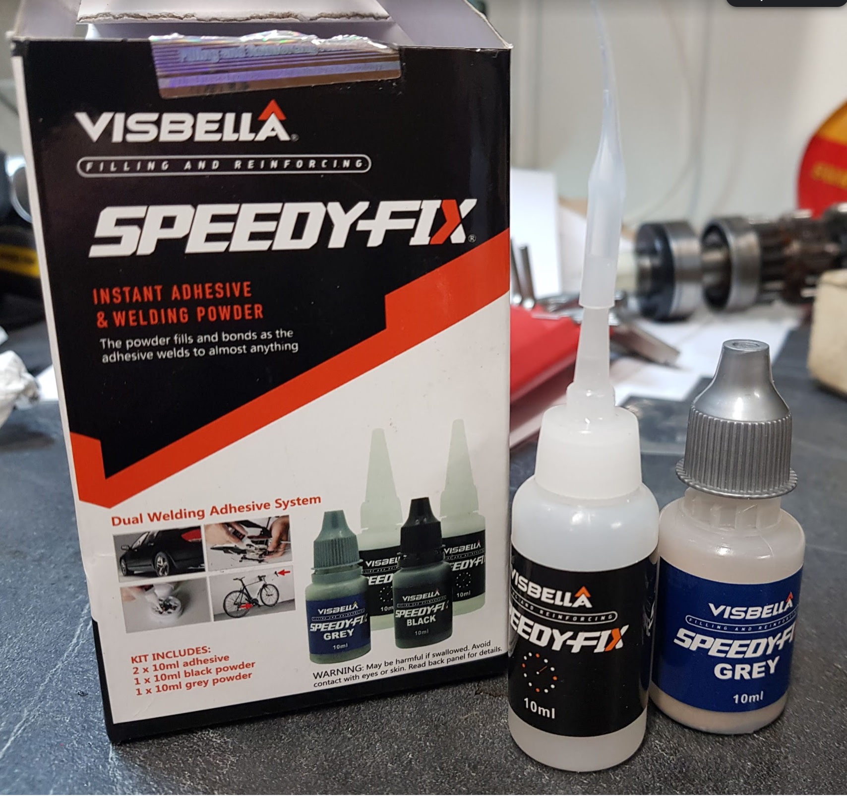
If something is too good to be true, .. it’s not true. That was also what I thought about Speedy-Fix, cost nothing from E-bay. Can it work ? Yes, I have tested it extensively on plastic, wood and metal. It really works. A totally damage plastic side cover was saved using this powder and hardener.

I could have TIG welded a tap onto the pin and pulled it out, but I don’t have any welding tools. Since the aluminium already had cracks I don’t think it added much structural damages to do the drilling and milling. A lot of materials left and if the gluing fails the set screw will still be in place.


Rust removal from gas tank

Electroysis rust removal:

After doing some research about how to remove rust inside the gas tank I ended up using electrolysis removal as an option I wanted to try. If you take a google search about the topic you will find different recipe and procedures.

Don’t use:

Baking soda is not good. It’s not the same as washing soda.

Can be used:

Citric acid can work but is not the best option.


Best in test:

Washing soda gives the best result. Use about 200-300g mixed with hot water and fill up the tank to the edge.

Washing soda is also the same as crystal soda.


How to do it ?

See the pictures below and click on the images for a better view.  You can use a battery,or as I did, an adjustable power supply to control the voltage and current. Connect the minus pole to the tank ( remove some paint to get connection to the steel ). Use a piece of steel as anode and dip it into the solution. Keep clear from the tank, use a non coductive material to isolate as shown on the images.  After some hours the andode must be cleaned to keep the current going. Pour water into the tank to keep the level at the top. When the anode is clean and the voltage is around 20-30V, the current can be 2-3 A. After some hours the current will drop and you have to clean the anode or let the process run for a longer period of time.

The GT750 tank below had very little rust from start of. I run the process one time for about 8 hours.

The anode after 8 hours:

Make sure the anode is not in contact with any metal in the tank. If it does, the voltage will be shorted.


GT380 tank:

The GT380 tank was much worse from start of and had a lot of rust. I let the process run over night, cleaned the anode and ran it once more for about 8 hours.


And no, this will not damage your tank. If you swap the plus and minus, then….. it’s game over. 

This recipe is probably the most gentle way of removing rust from your MC gas tank.


GT380 Gear shifting

Step 1:

The needle bearing for gear shifting cam must be installed again. Use a socket to drive the bearing in place.

The needle bearing seen from the inner and outer side of the crankcase.


Step 2:

Cam and forks mounted:


A greate help to look at the pictures taken while stripping down the engine :


GT 380 Crankcase and cylinders

Cleaning :

All parts were laid in a bath of pure paraffin overnight to loosen up the old burned materials.

Thereafter, cleaning with a brush and flushed with water.


Powder blasting:

The powder blasting came out pretty well, but it’s messy, powder all over the place, everywhere. Inside my body as well… The biggest benefit is clear, no dangerous particles to damage the engine. It’s baking soda and can be flushed away. The moste resistant parts are hard to get off with only powder blasting and the finish of the alu parts get’s not that nice using powder.

Since I already have invested in a sandblasting cabinet I decided to stop the messy powder thing and loaded up the cabinet for glass blasting.


Glass blasting:

As always on my blog, click on the images for a more detailed view.

Much cleaner and more fun to do the glass blasting. The biggest issue will be to be to get rid of all the glass particles. Rinsing in water and blow dry with compressed air is important.


Coating with oil:


The parts looks shiny and nice after glass blasting but will soon start to oxidize. I was recommended to use a good penetrating oil, like Omega 636 to preserve the crankcase. Let it soak for one day before drying off.

And again, blow very well using compressed air to get rid of all remains from the blasting media.

So much more fun to start the assembling of the engine when all the parts are cleaned and shiny.  🙂  🙂

Assembly of the rear wheel

Assembly

The brake shoes had little wear and were reused after cleaning and glass blasting.

New sprocket mounted

The spacer on the other side ( no 10 on the drawing)


New seal mounted and well greased before and after the last spacer was placed.


Mounted


Mounted on the bike, please see the drawing below for details. Remember, the entire parts manual can be found in the folder “documents”


Rear fender

Rear fender mounted:

Hmm,perhaps I should give it some scratches, if so, the first one coming later on will not be that annoying 🙂

The inner part of the fender was painted with HAMMERITE metal paint for rust protection.


Lamp and bracket mounted: 

The mounting holes for the plastic part of the fender were both broken. Used a plastic repair kit called Speedy Fix. Worked extremely well. Used the same kit to repair the side cover.


GT 380 Fork

Fork:

Hmm, a bit confused… Looks like the parts inside the fork is a mix of L and K (J) model ? Not sure, but both inner legs must be replaced with new ones. Marks and scratches on both.


At the moment I have ordered one of the inne tubes, 5111-33030. This is a hard to find part. Not sure if I can swap to later models. The lower part, the oute tube must be the J or K model because of the drum brake.

Sanding and polishing the outer tubes:


Lamp head , fork bracket parts:

What I did with the shiny parts: Sandblasted the rust at the inner side and painted. Cleaned and polished the outer part. One of the chromed parts was too bad to be cleaned. I had to turn off some metal using my lathe, sanded and polished well before I nickel plated the part. All the old chrome must be removed before the nickel plating.

GT380 Frame assembly

Frame and swingarm ready to be assembled

As always on my blog, click on the images for a more detailed view.

All bolts are reused after cleaning and nickel plated.

The front and rear wheel bolts before and after nickel plating. I use the same old nickel plating kit from six years ago when I restored my GT750 A model.


Shock absorbers and centre stand mounted


Steering Stem:

Pictures from dismounting:

The bike has been upgraded previous with tapered roller bearings. I will of course keep it so. The steering stem is different and has no threads at the outer side like the original one, only internal threads. The bolt at the top looks ugly and I will make a custom build “nut” at the top so it looks as close to the original nut as possible. Will use my lathe and milling machine to do so + nickel plate the part.


Next step, machining the bolt:

Turning the 10mm axle on the lathe.

10mm fine pitch 1,25mm threads.

Machining on the milling machine.

Done and polished, before nickel plating.


Nickel plated.

Mounted, I’m very pleased 🙂


GT380 wheels, mounting of spokes

GT380J, mounting the spokes: 

The procedure of mounting spokes is well explained in an earlier GT750 post. Please read the post before continue on this one.

GT750 post:

http://mc.grenasberg.no/2018/10/28/front-wheel-spokes-mounting/


Front wheel:


As described in the GT750 post, always start with the spokes at the inner side of the hub. And don’t mix the spokes. Inner and outer are different. Get the details from the post mention above.


Turn the wheel and continue with spokes at the inner side of the hub.

Arrange the spokes before mounting the nipples.

Both inner sides done.

Next step: mount the spokes at the outer side of the hub:

Turn the wheel and and mount the remaining spokes

Done, all spokes are mounted.


Rear wheel:

Do the rear hub in the same way as shown for the front hub.


The adjustment procedure will be the same as shown in the GT750 post:

Adjustments:

http://mc.grenasberg.no/2018/11/04/spokes-adjustments/


GT380J Front and rear hub

Step1

Cut off all the spokes and remove ball bearings.

Step2: 

Cleaning and glass blasting.

Step 3:

Grinding. Did no grinding to the rear hub. You can still see the scratches from the spokes. Will not be that visble when new spokes are mounted.

On the front hub I grined quite a bit to get rid of the bigges scratches. Started with P250 paper and thereafter P1000.

Step 4:

Rear hub after polishing:


Front hub after polishing:

Step 5, bearings

Mount new bearings, don’t forget the spacer in the middle before you mount the last bearing.

Be gentle when driving the bearings into position. Allow some slack to the spacer so each bearing can individually move freely.