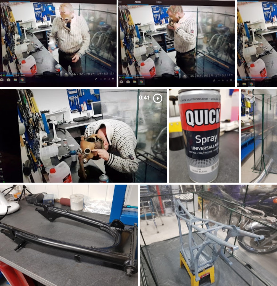
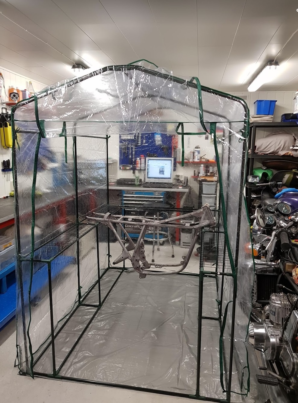
The greenhouse is ready for the first paintwork job.
Warm and cozy indoor, minus C degrees and snow outdoor.
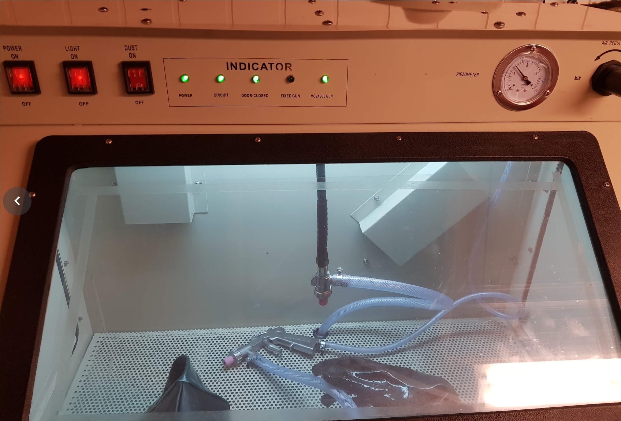
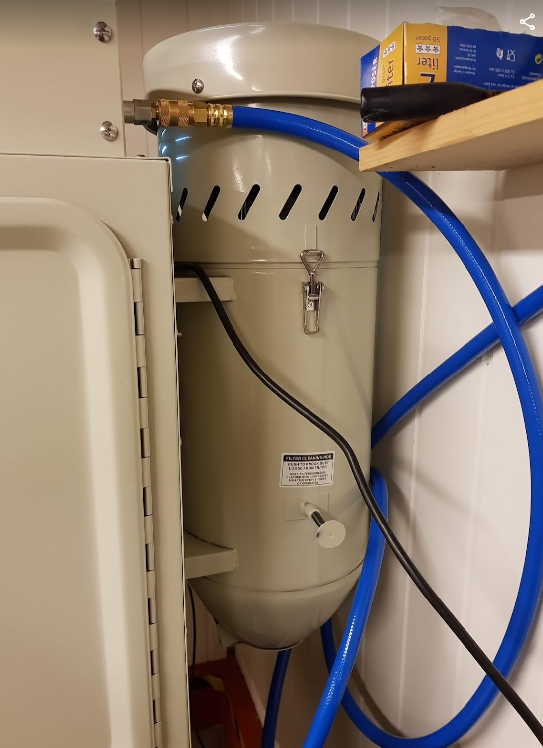
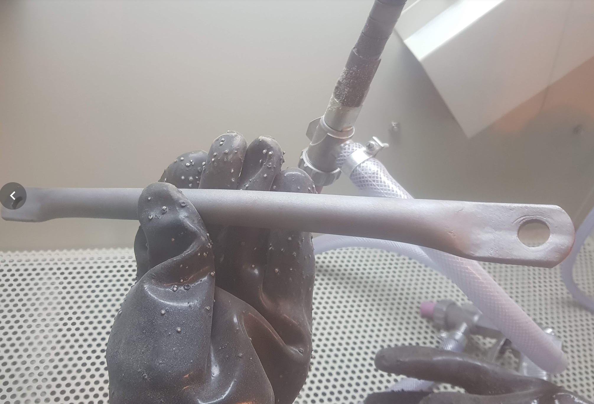
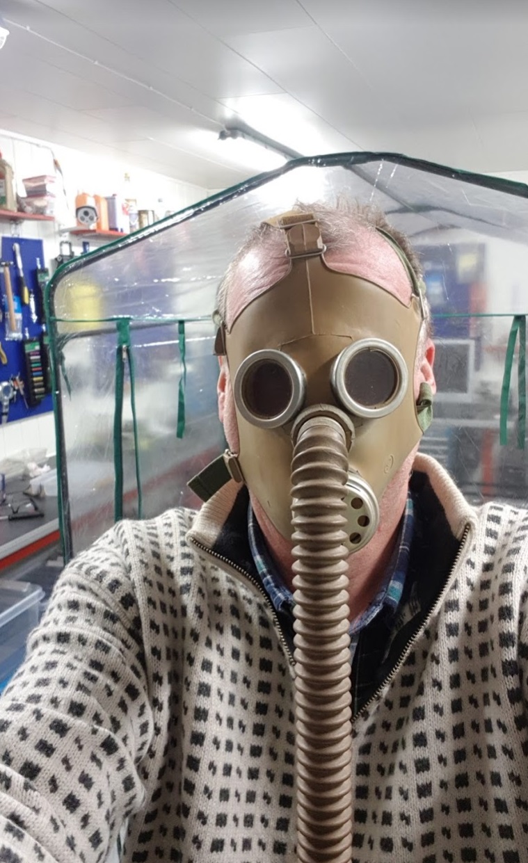
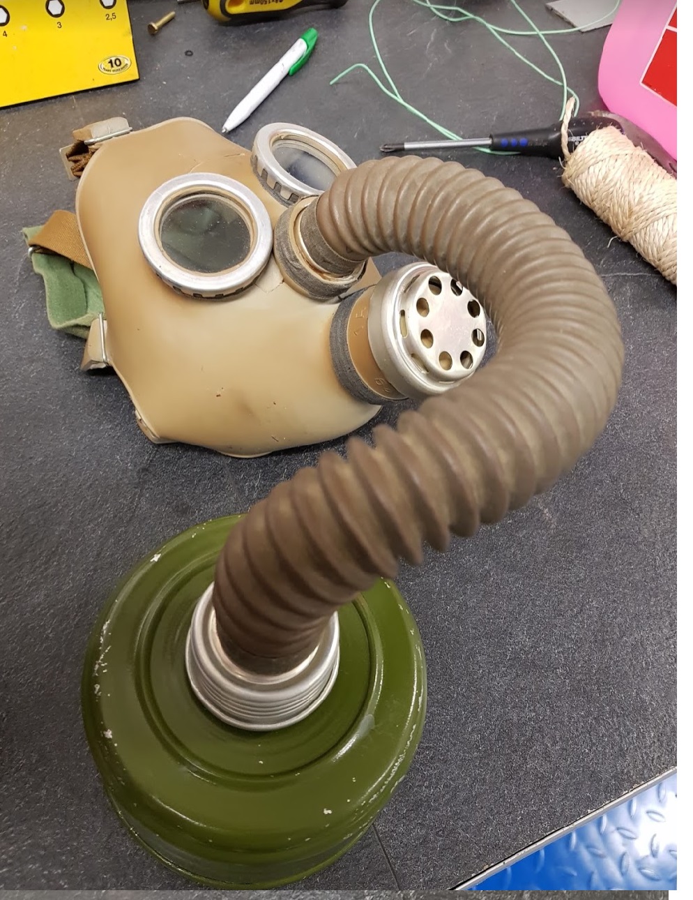
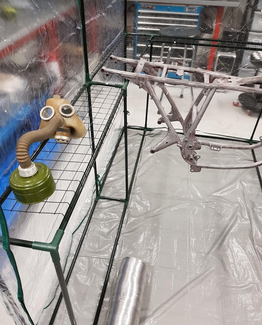
Ventilation is on and the 70-80 years old gas mask from WW2 will become handy.
80 years old gas mask giving breath assist while painting a 40 years old frame.
The mask is awesome, brand “new” from the war and works 100%
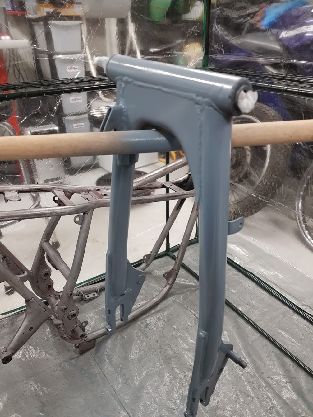
Primer applied.
Next day:
First layer of paint sprayed
Leave it to dry for the next day.
Have to say it again: not a bad idea to mount the greenhouse 🙂
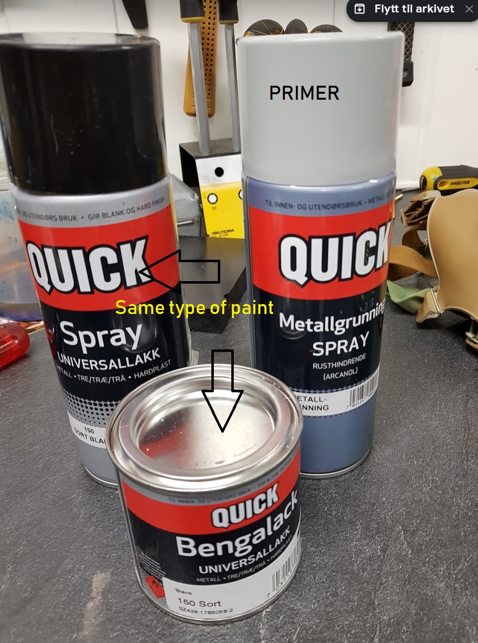
No, it’s not 2k products. Not so durable but more easy to apply. The main reason to use this recipe is the following:
The paint in the can is the same type as in the spray can. Regardless if you use 1k or 2k paint you will sooner or later get scratches and marks in the paint. If so, I can easly use a brush and touch up wherever it’s needed, with the same type of paint. Important to use the correct type of primer, if not the paint can start to boil and it’s game over…..
The mask is comfortable to use and has a stunning look 🙂 I don’t smell anything from the solvent while working inside the greenhouse. If I later on become a doomsday prepper I already have the gas mask. I think I also have the blue nuclear brush from my military service. WW3, come and get some… ha, ha.
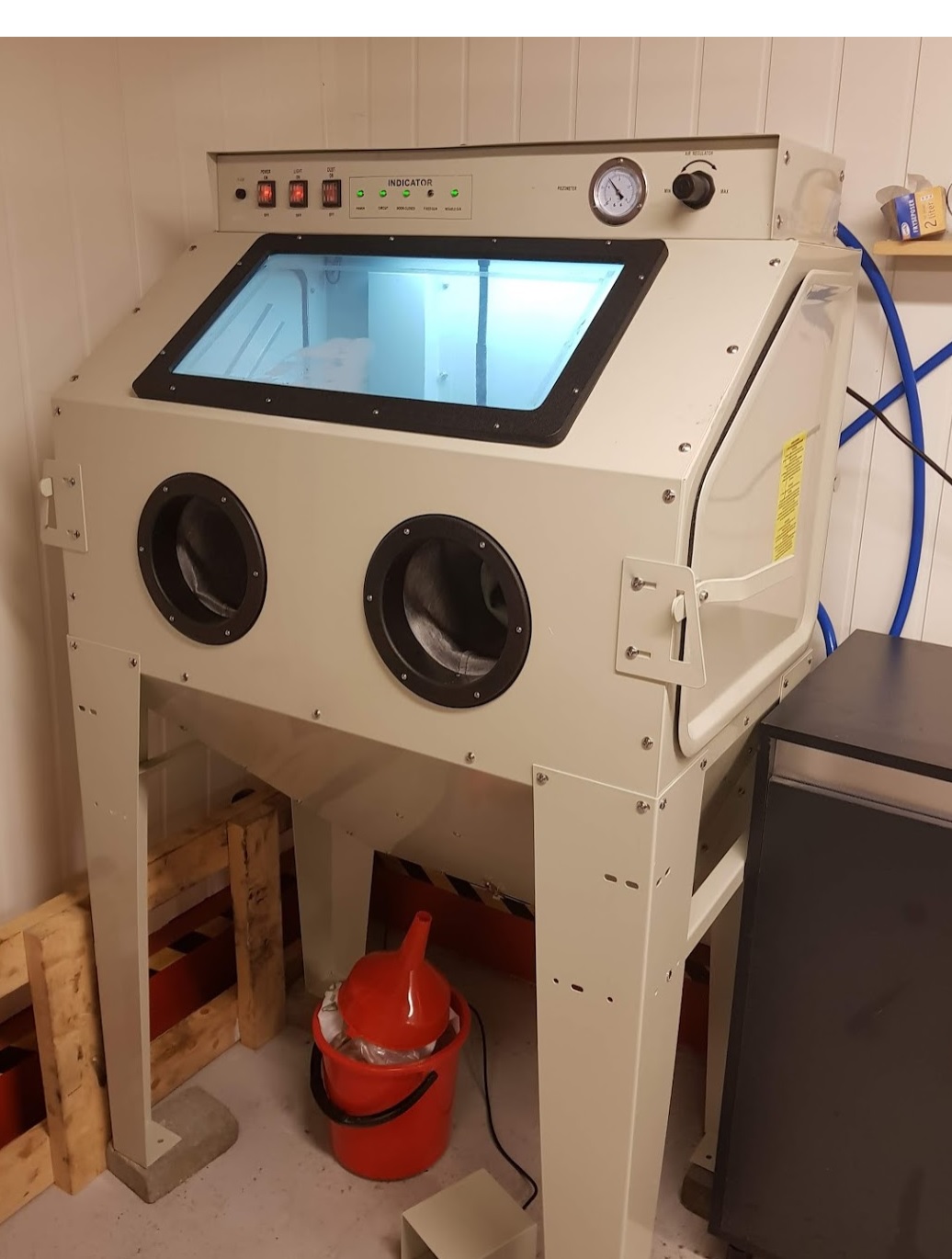
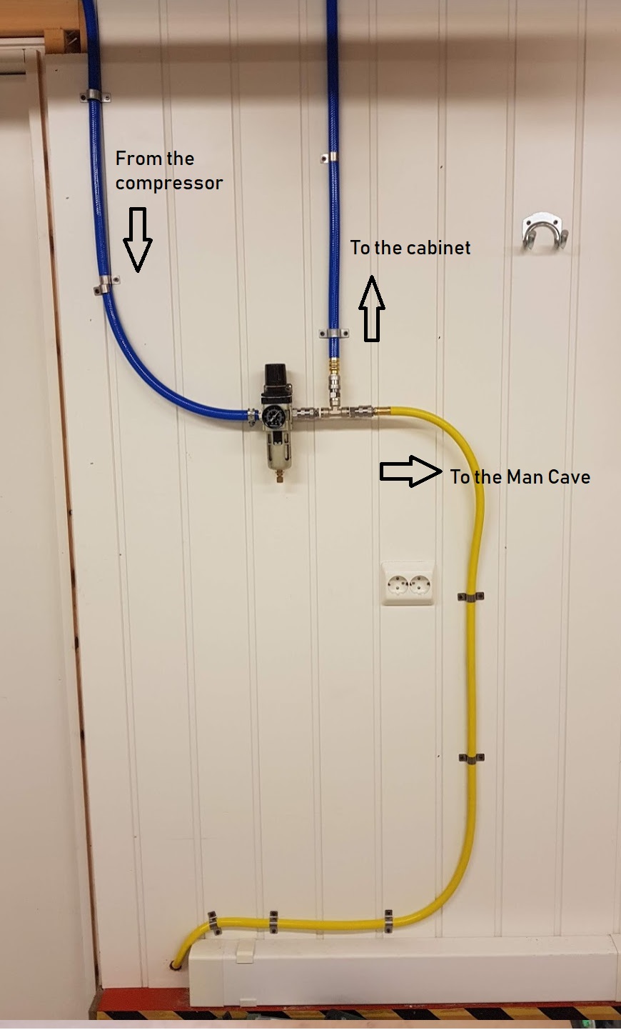
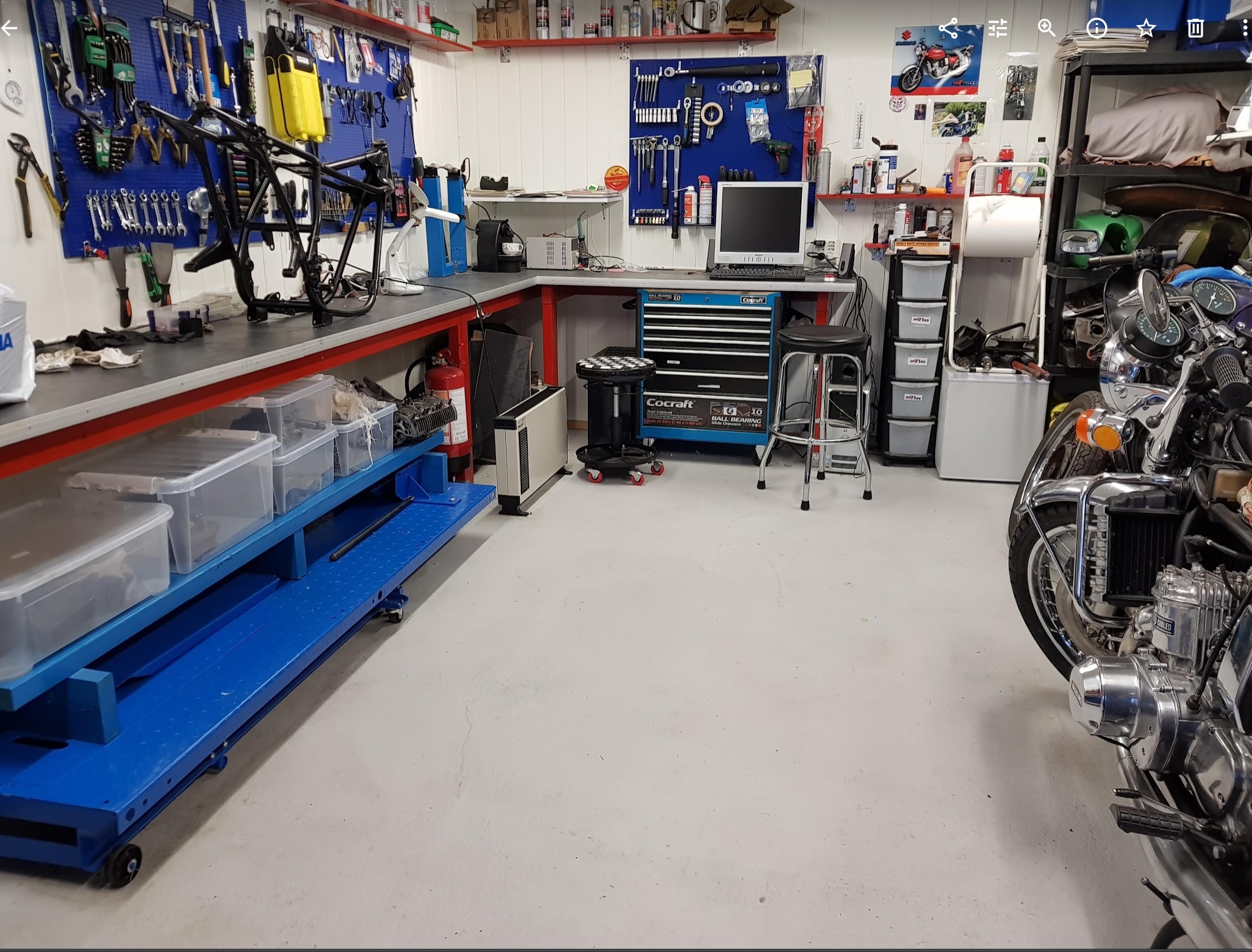
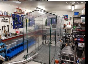
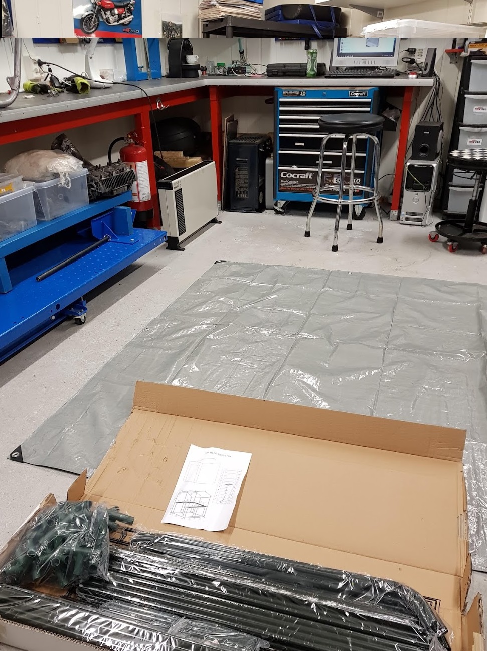
The heat is always on in the Man Cave and the temperature will be ideal for painting. A greenhouse will give the protection needed for the work. Can’t use spray cans without a tent for protection. A low cost greenhouse will do the job.
As long as it’s winter outside and freezing cold the paintwork has to be done inside.
Quite easy to assemble, took me only about 30-40 minutes.
Ventilation in place + an unused gas mask from WW2.
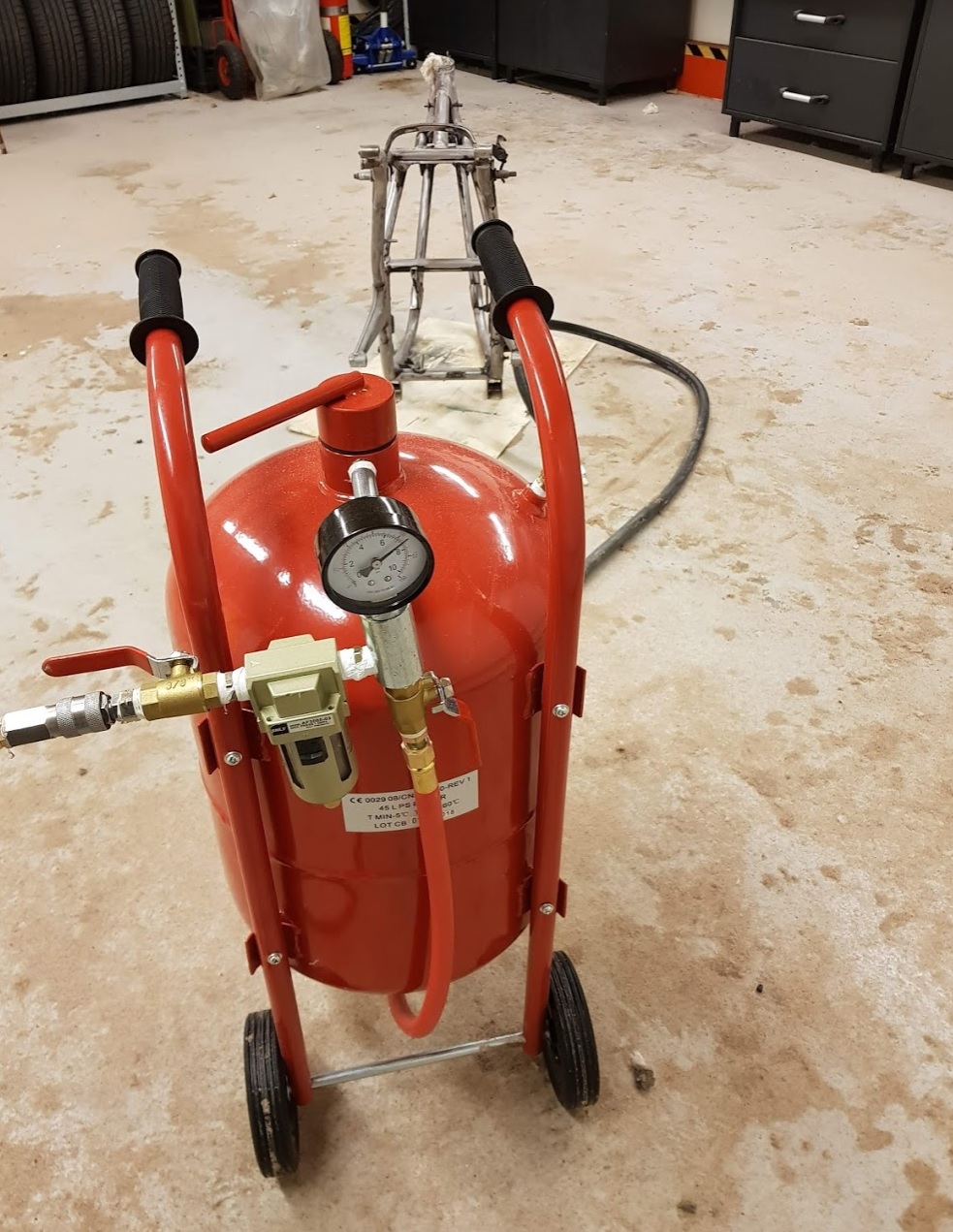
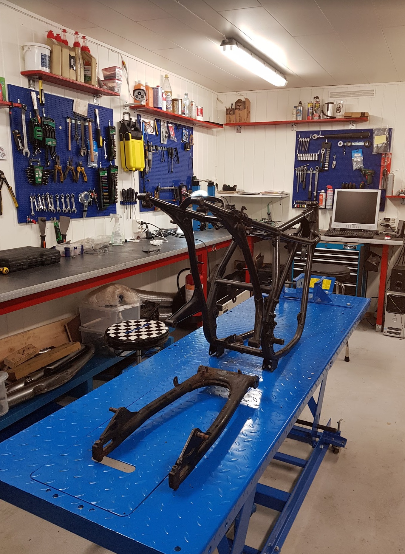
Winter outside and the cars had to leave the garage while I did the sandblasting.
Bought this sandblasting kit at a very low price. Quality looks ok, except from the nozzle. Can replace later on with another gun, but it did the job. A lot of sand, all over. In the garage, everywhere, inside my body as well 🙂
Done, ran out of sand. But where to do the paint work ?
Can’t spray in the ManCave, or can I ? Yes , I can. A tent or a greenhouse will be fine.
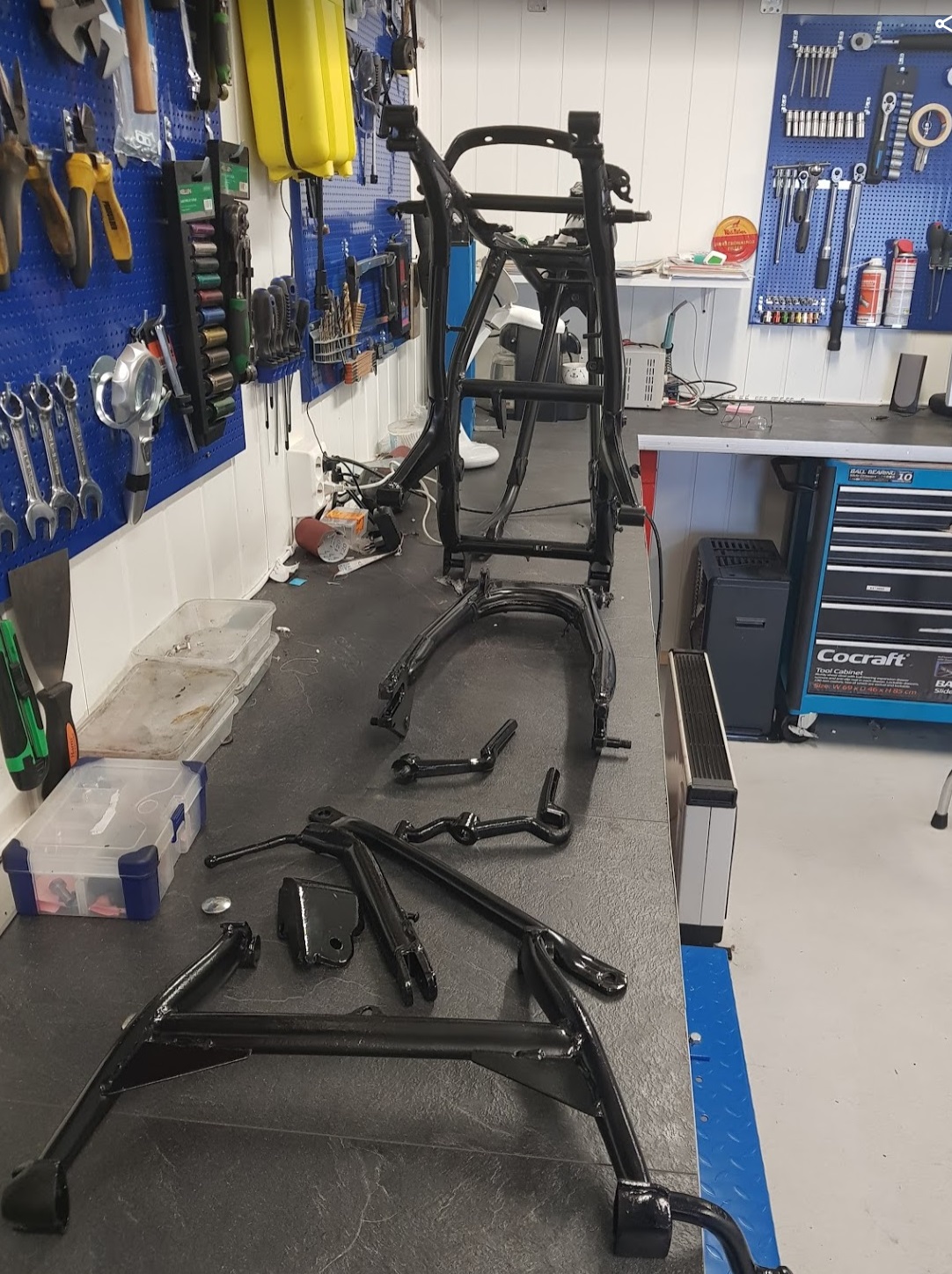
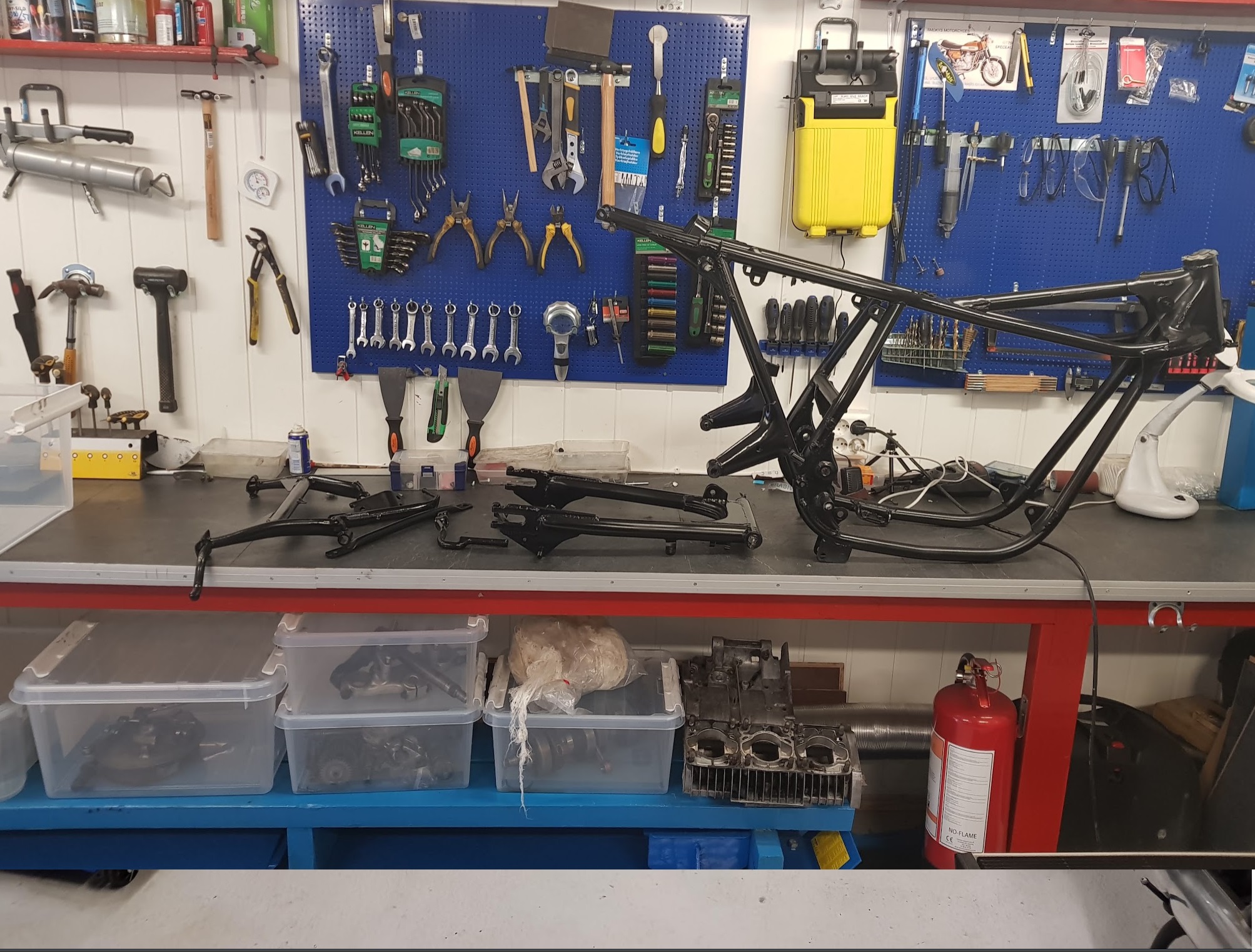
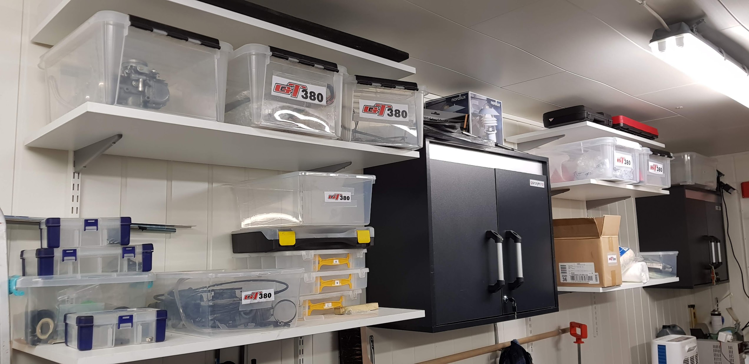
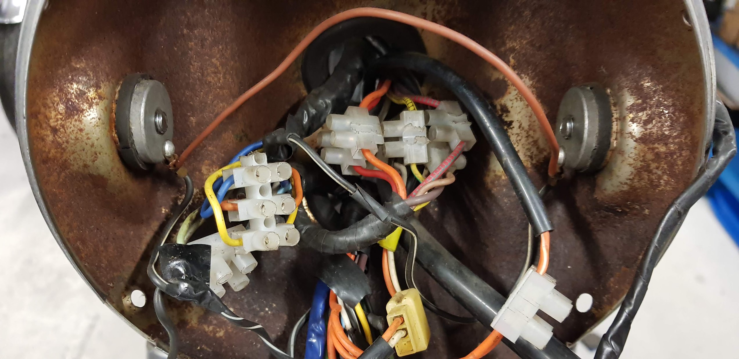
Quite easy, not much can go wrong. I’m trying to sort and organize all the parts stored in boxes and plastic bags with labels on.
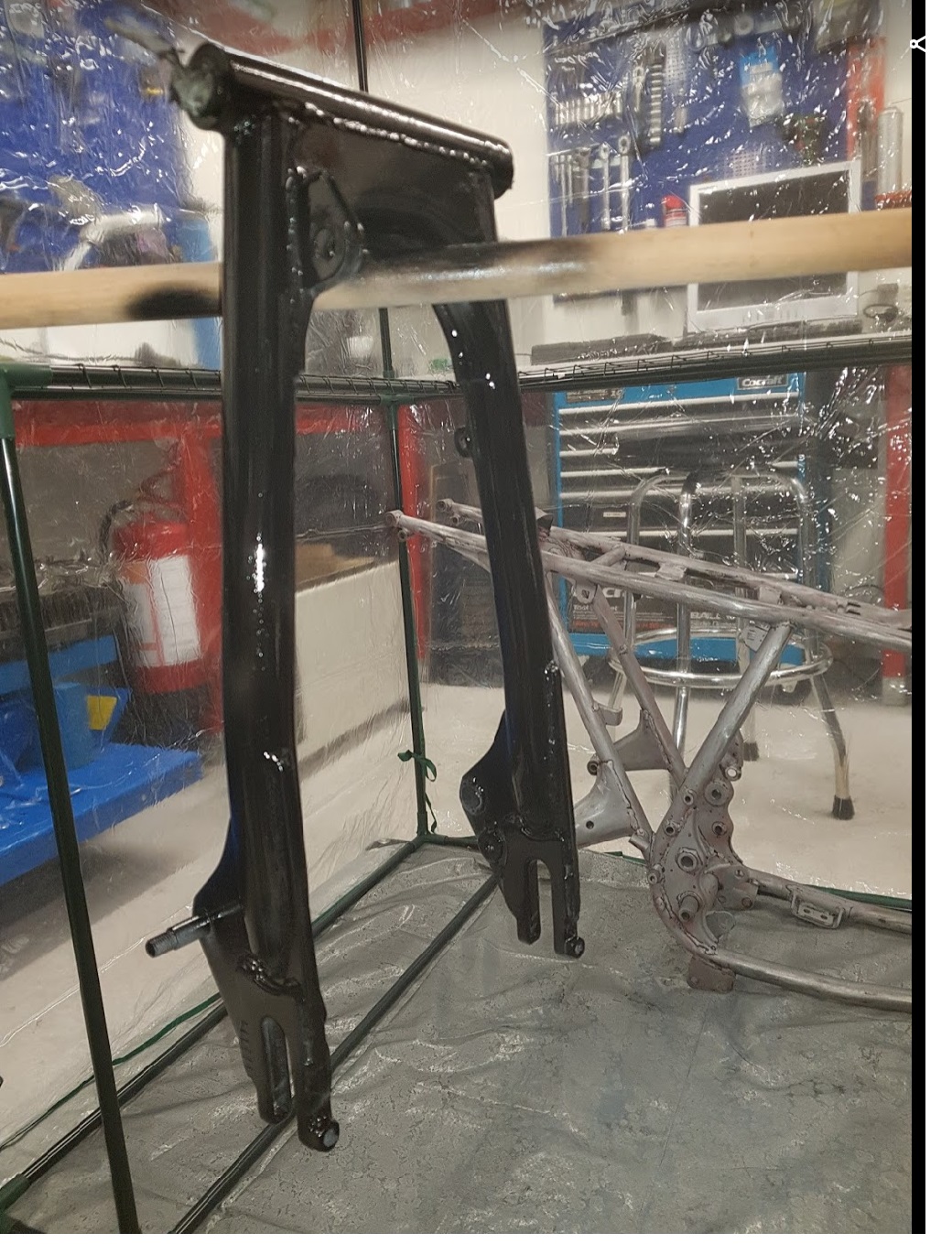
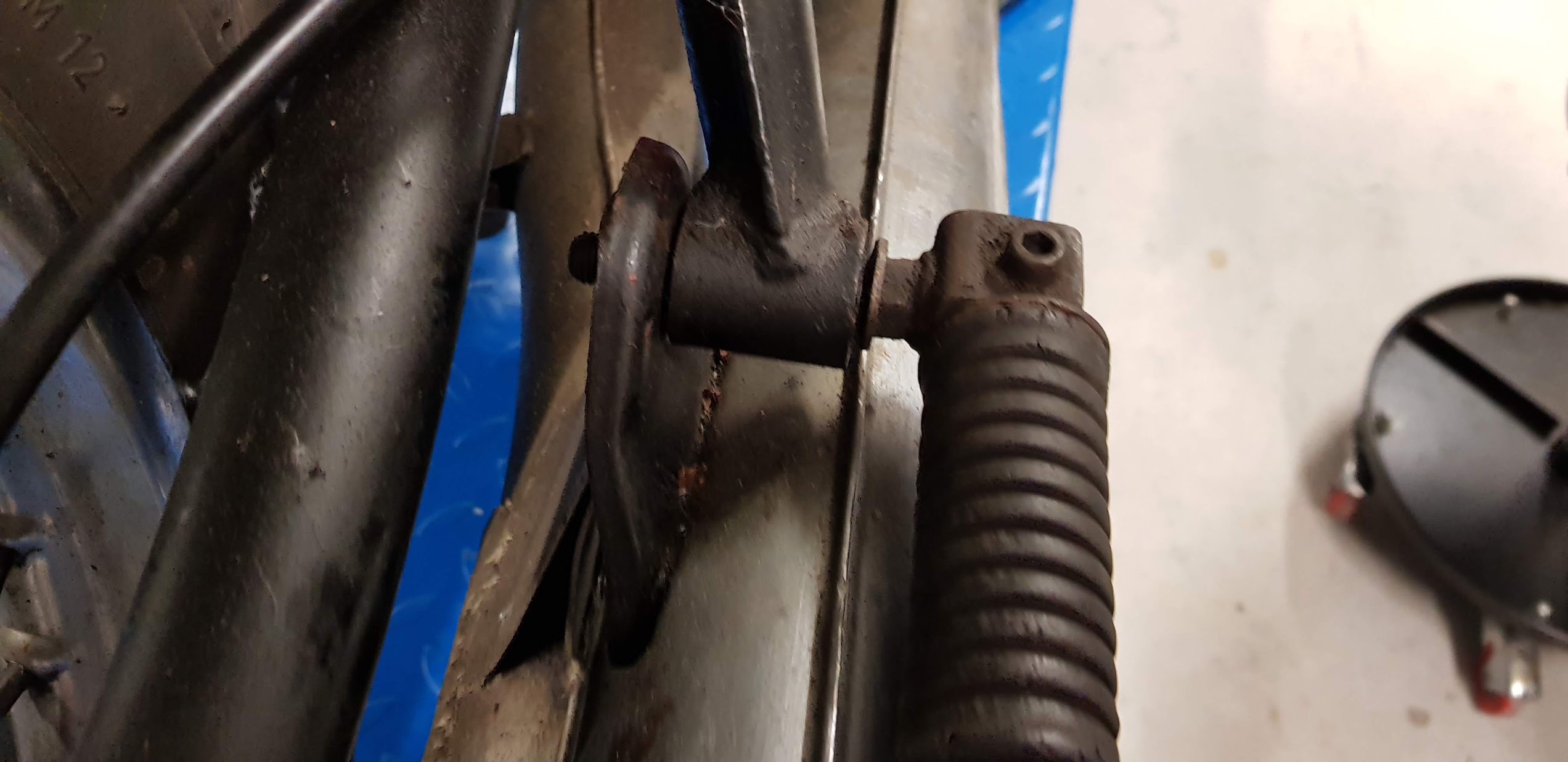
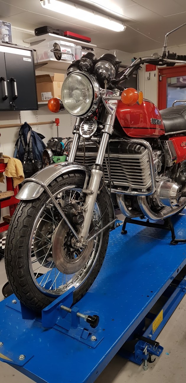
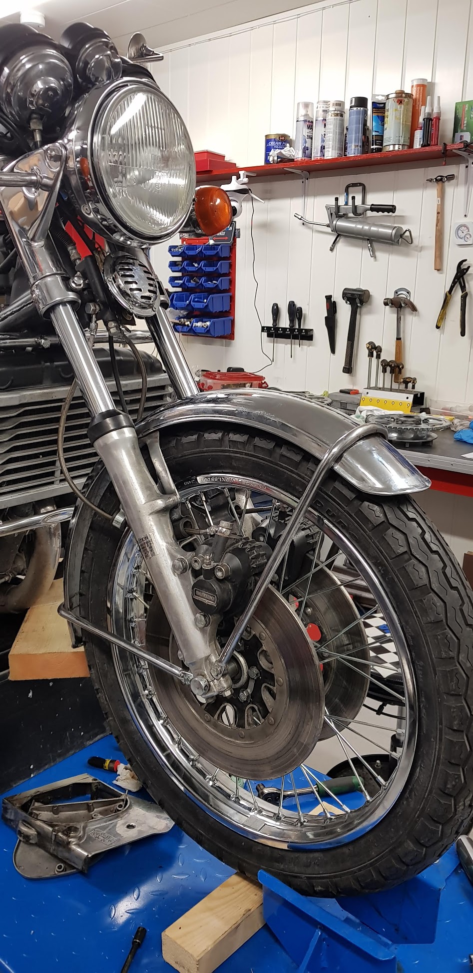
Front:
How to remove the fork:
loosen the bolts marked with yellow arrow and pull, drag or knock down the tube until it’s off. All the brackets on the picture are now free and can be removed.
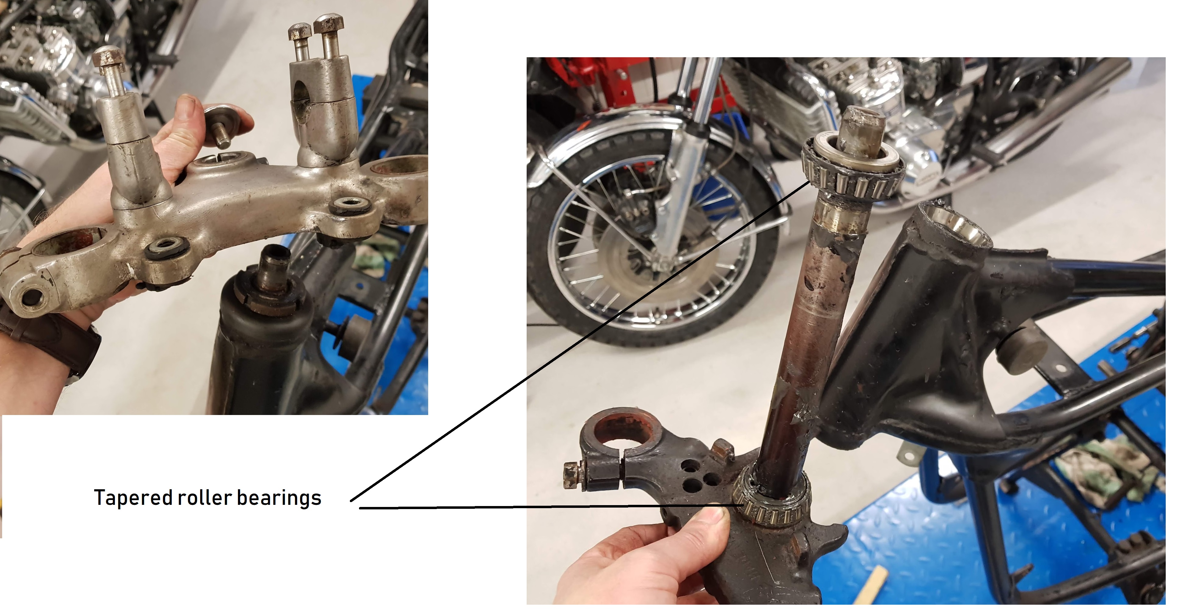
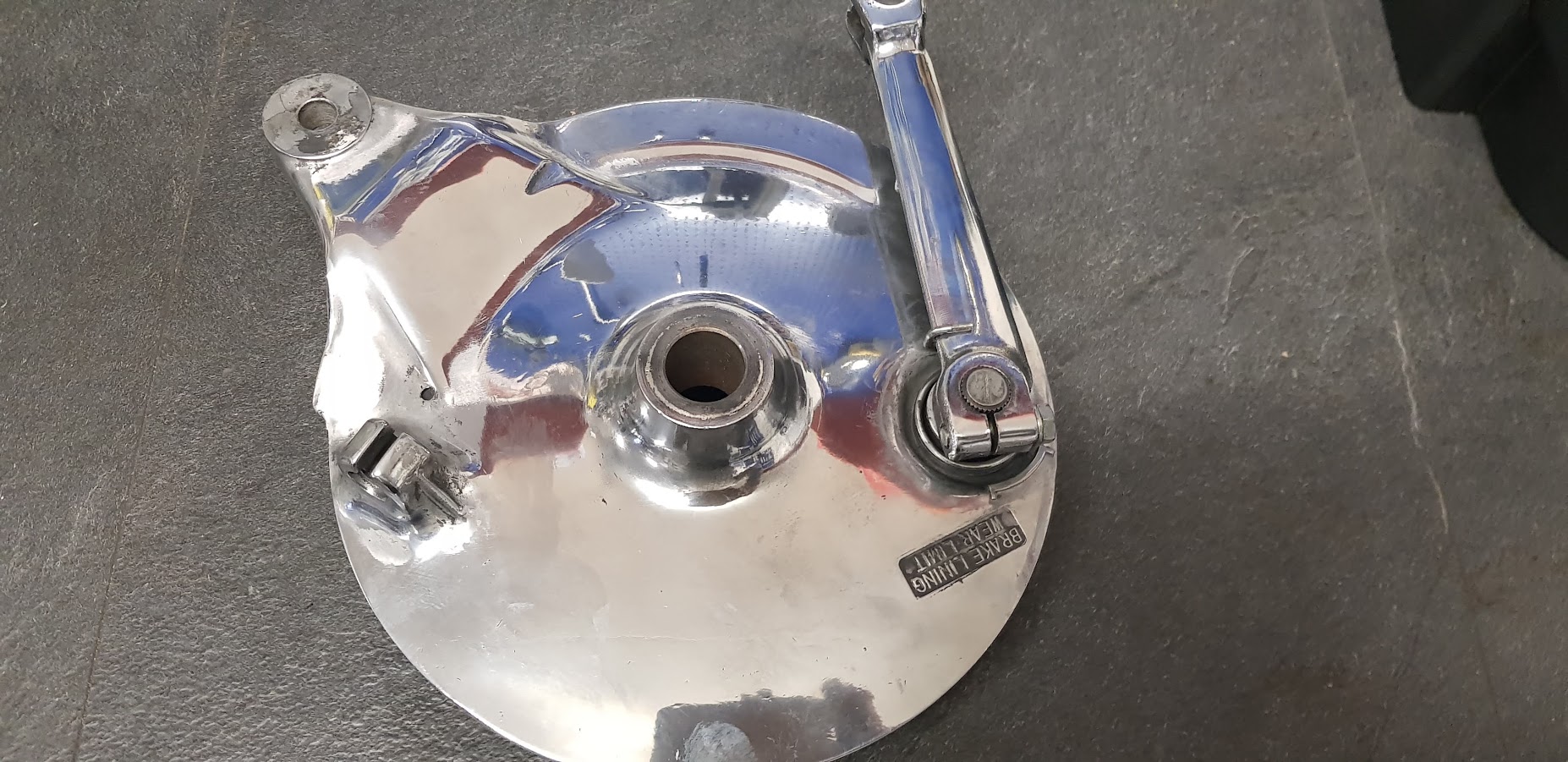
Stearing:
Not sure if this is original from Suzuki. My GT750 had standard roller bearings, not tapered.
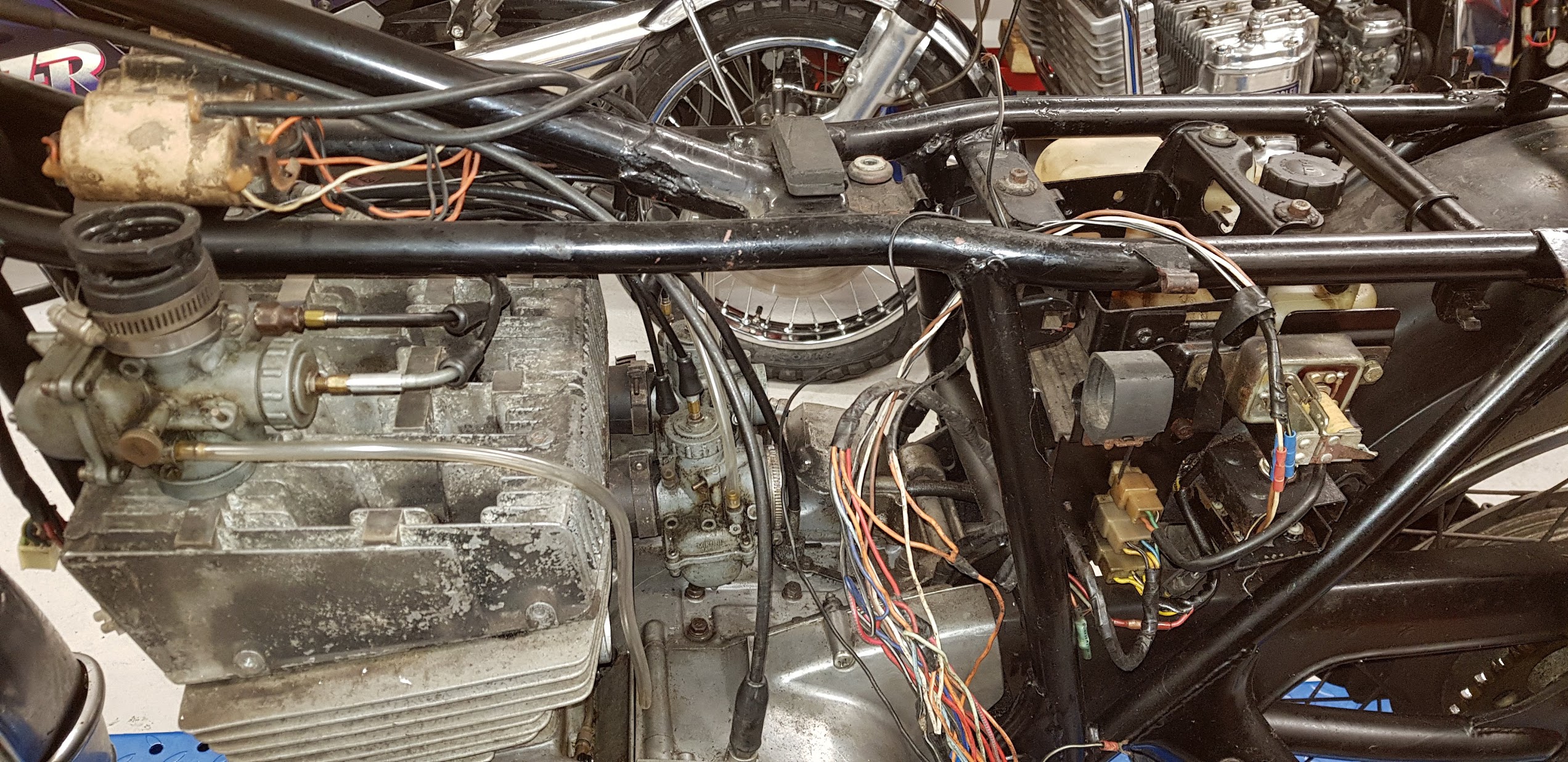
As always on my blog, click on the images for a more close up detailed view.
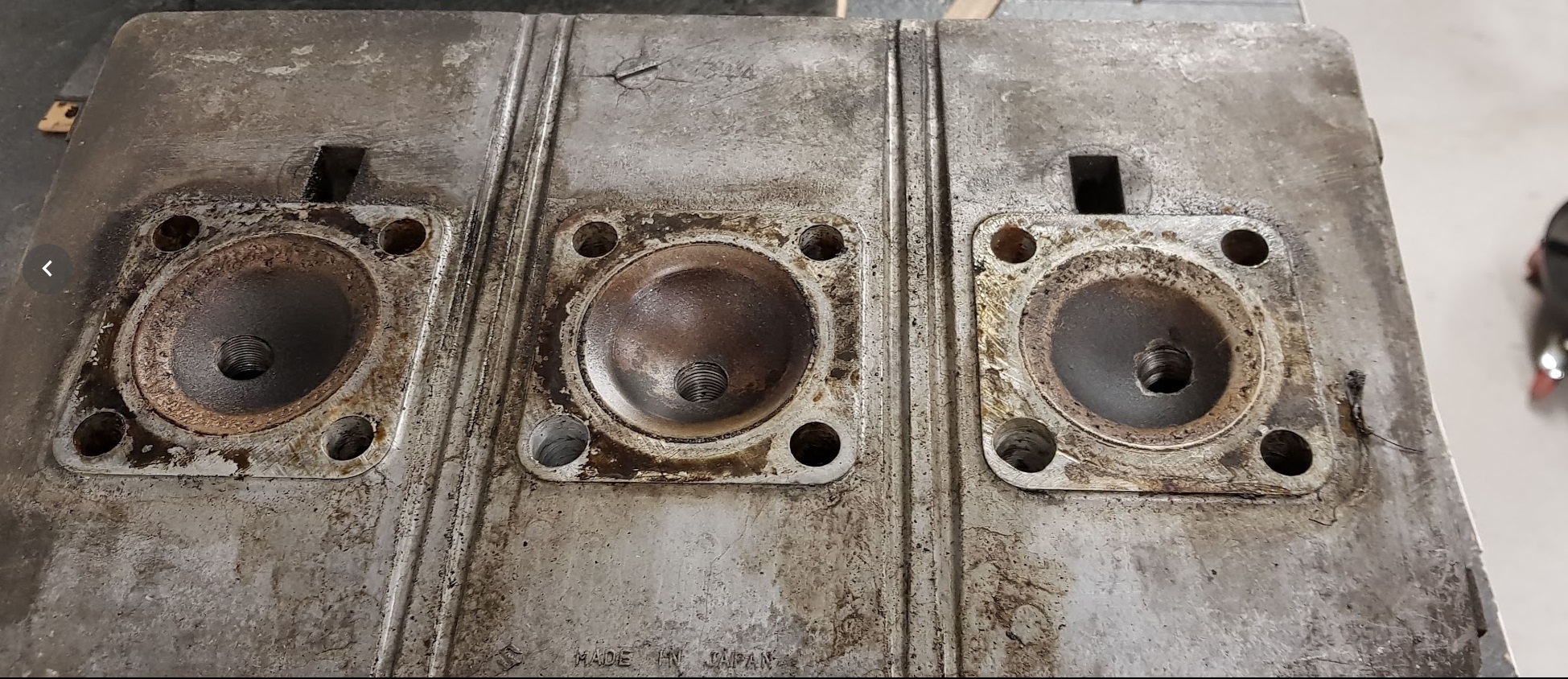
Remove all 12 nuts from the cylinder head. Use a rubber hammer to knock it loose.
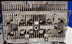
Bottom side of the cylinder head.
Step 2, removal of cylinders:
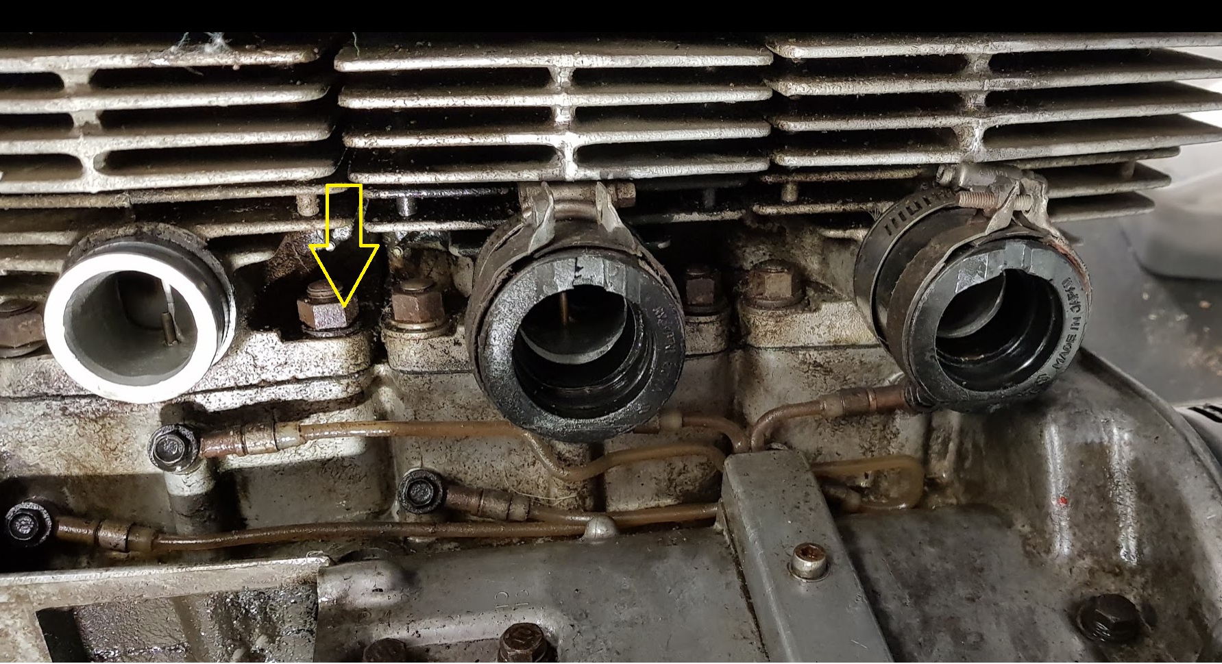
Remove the nuts holding the cylinder. Four of them for each cylinder, see the yellow arrow.
The cylinders should come off quite easy. Three individual ones, not one big block as on the GT750.
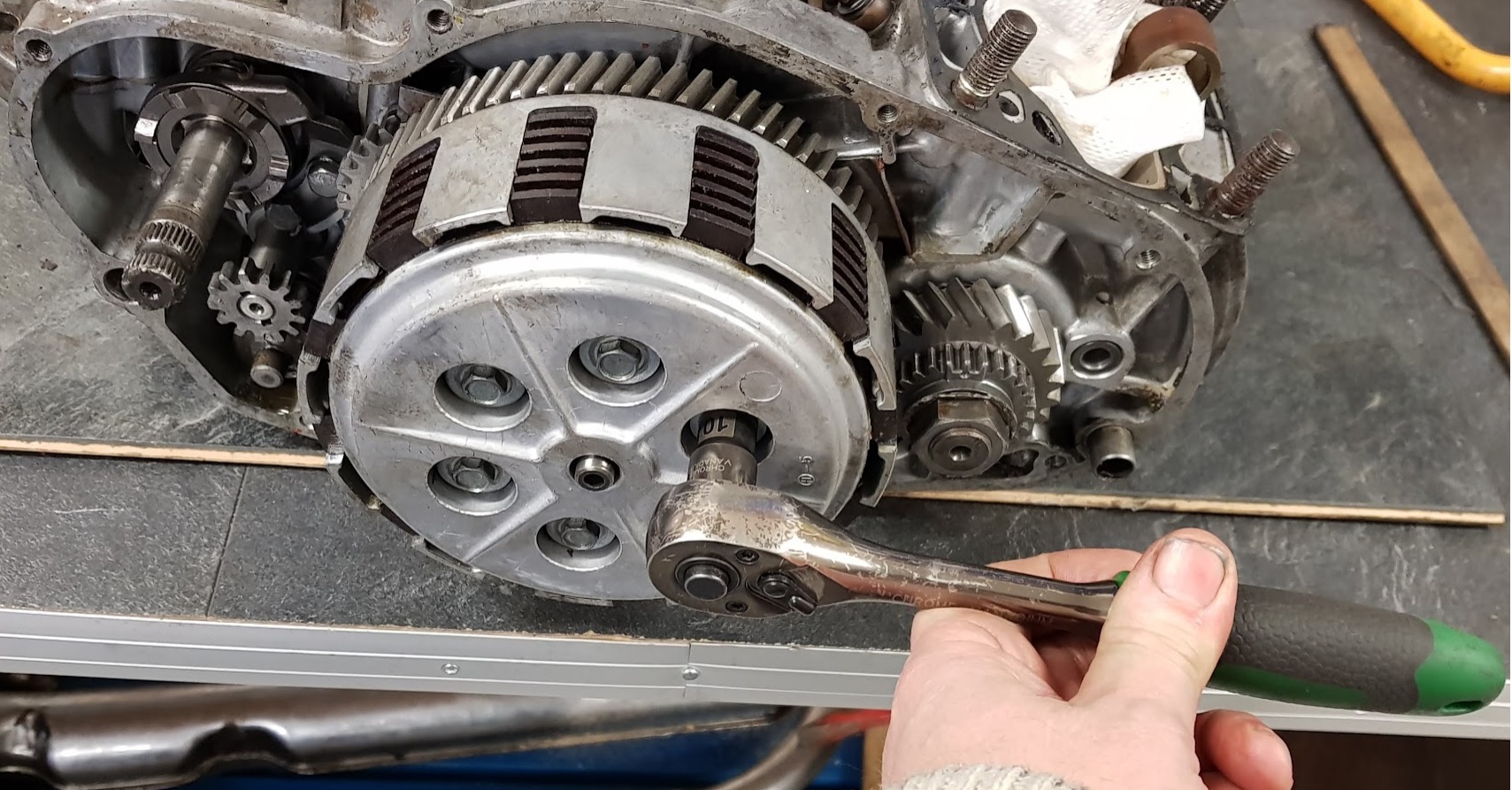
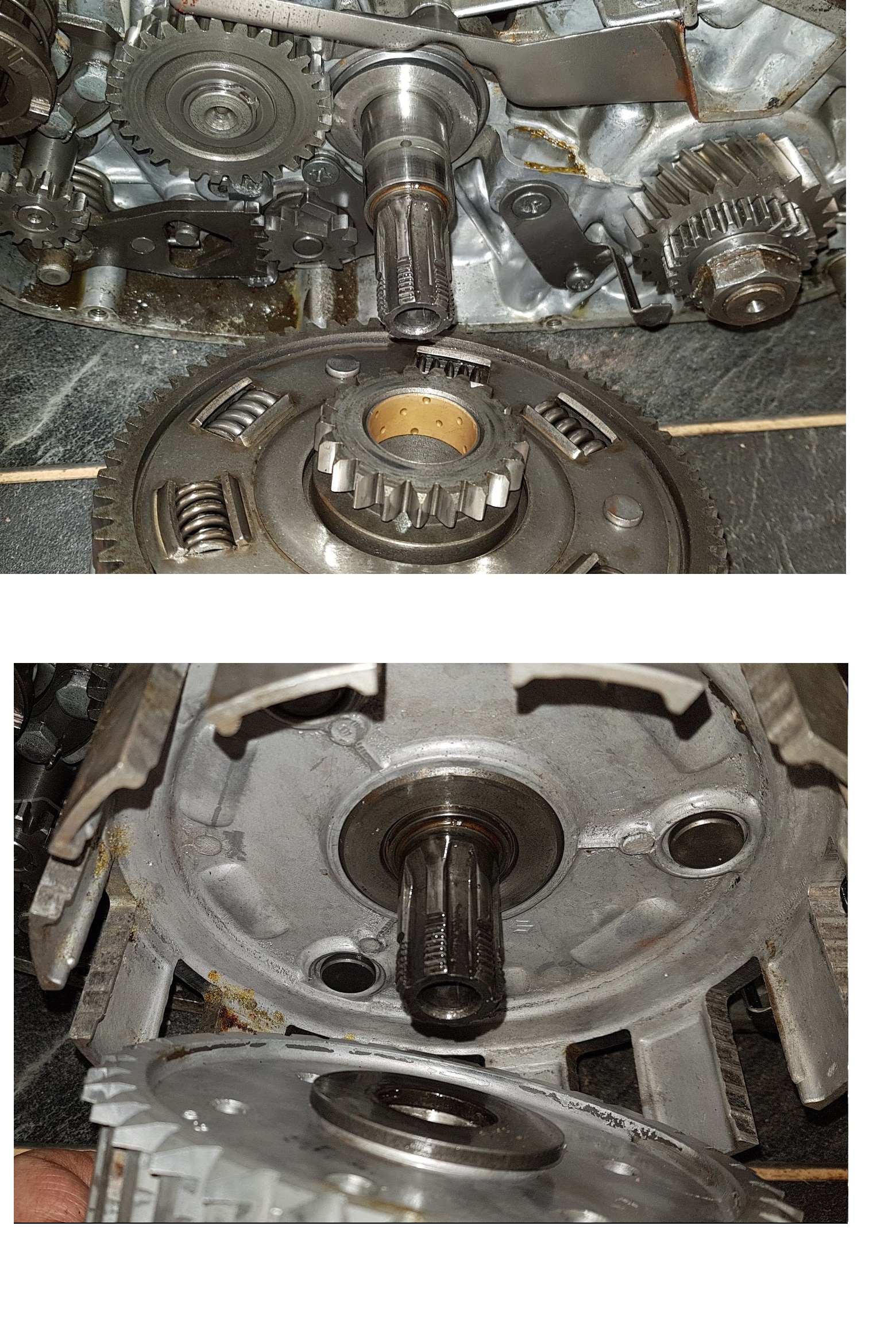
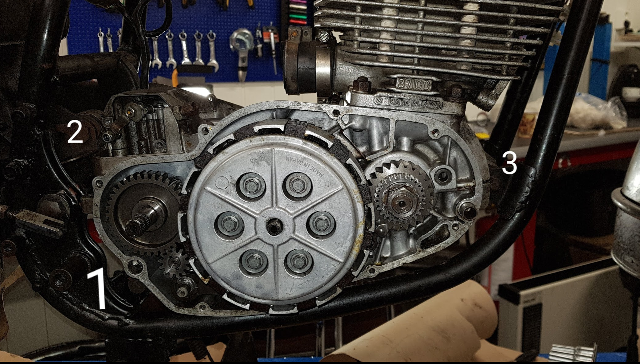
Step 3, removal of clutch :
Give the wrench a tap and the bolts should come loose.
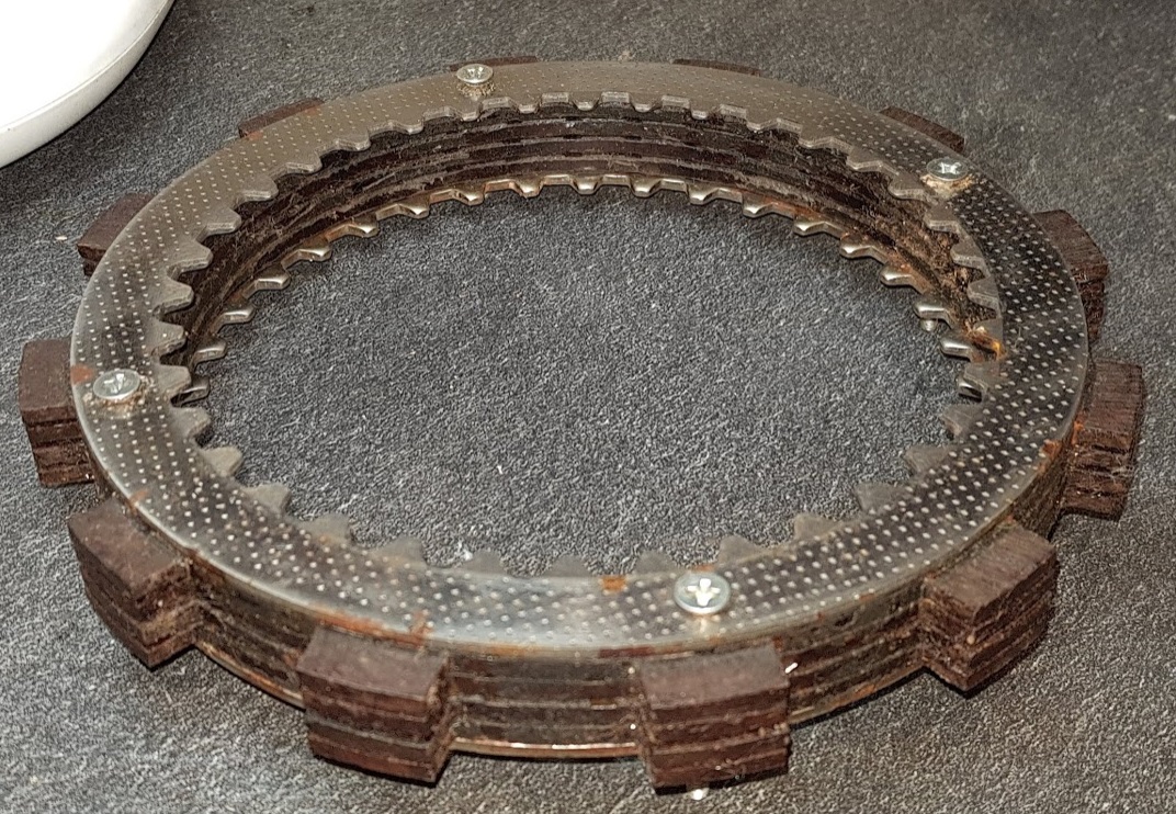
Put all the parts together in a safe location so you know where to find them later on.
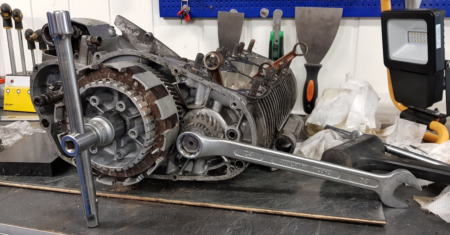
Remove the axle part
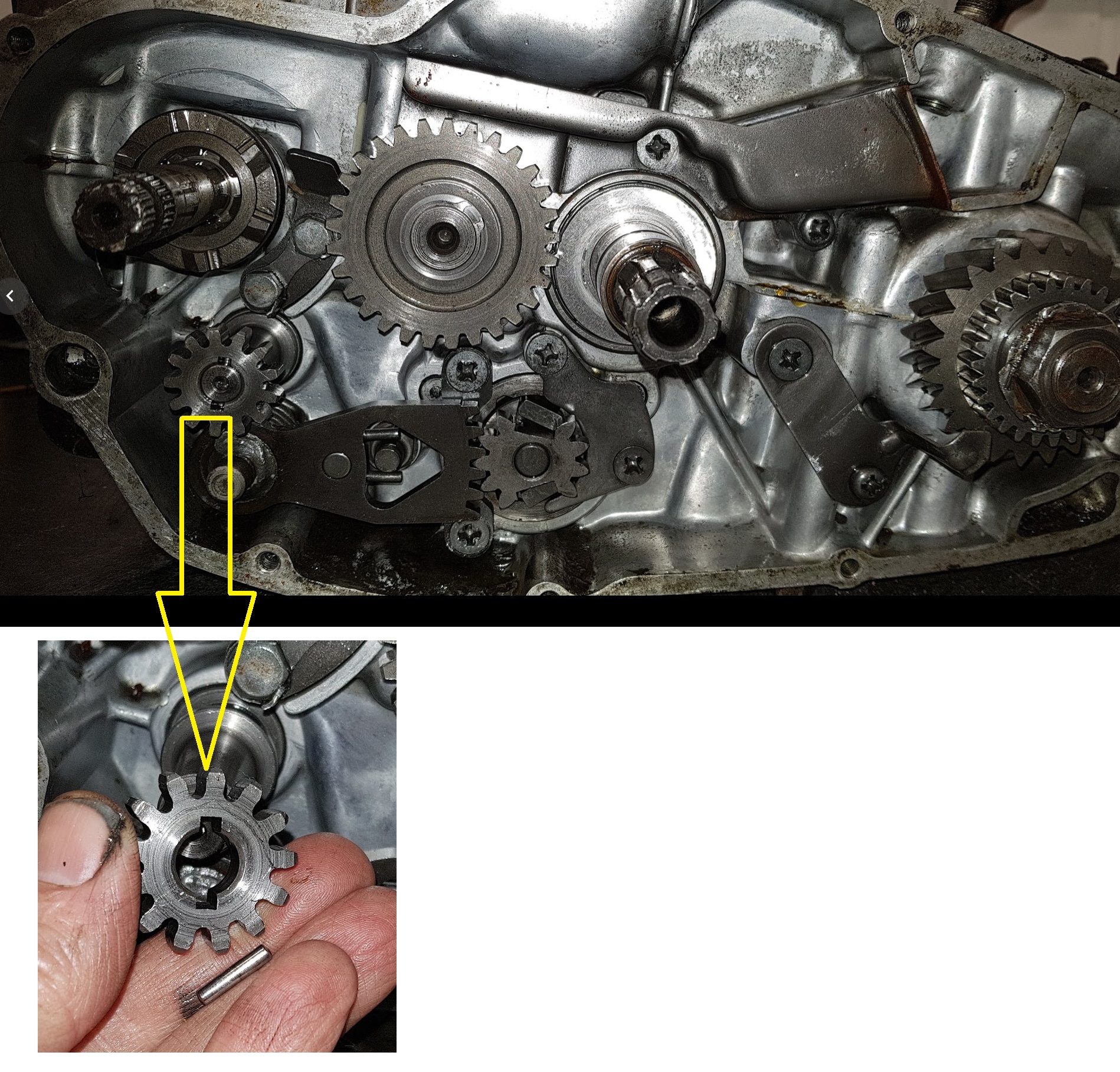
The big nut in the middle can be hard to get off. You somehow have to lock the clutch from spinning too. And of course, bend the lock washer straight before you start.
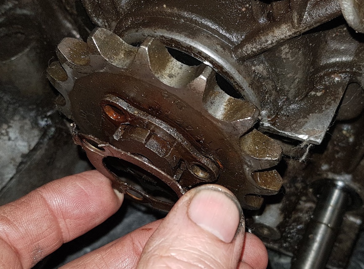
You can buy a tool for this, but I made my own using the rusty part from the clutch. Drilled 3 mm holes and screwed the fiber and metal discs together and put them back into the clutch house.
Like this:
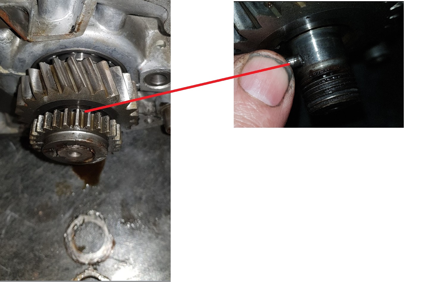
Locked the crank using an extra key and…..hmm, off it went, Phuu !
Keep track of the parts for the assembly process to come later.
Step 4, more parts to be removed:
Front sprocket:
Step 5, loosen the crank :
Block the crank using two wooden sticks.
That nut was really hard to remove. Had to use a butane/propane torch and heat up before it came loose.
Keep track of all the parts !
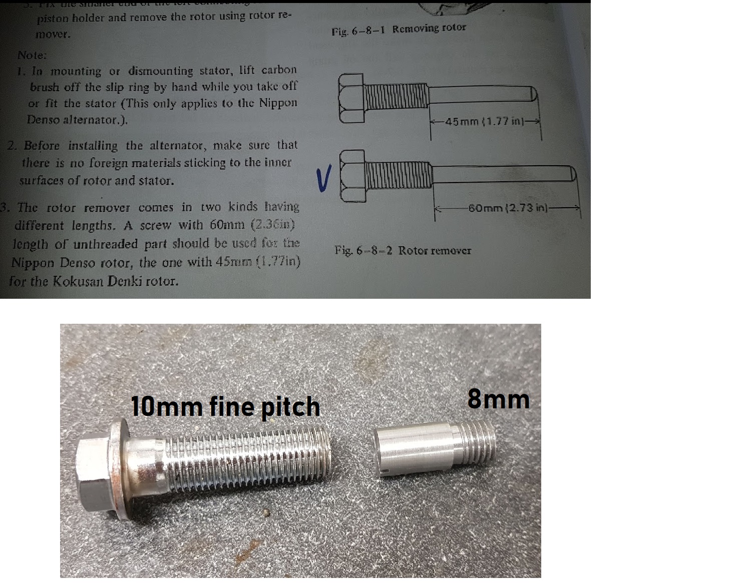
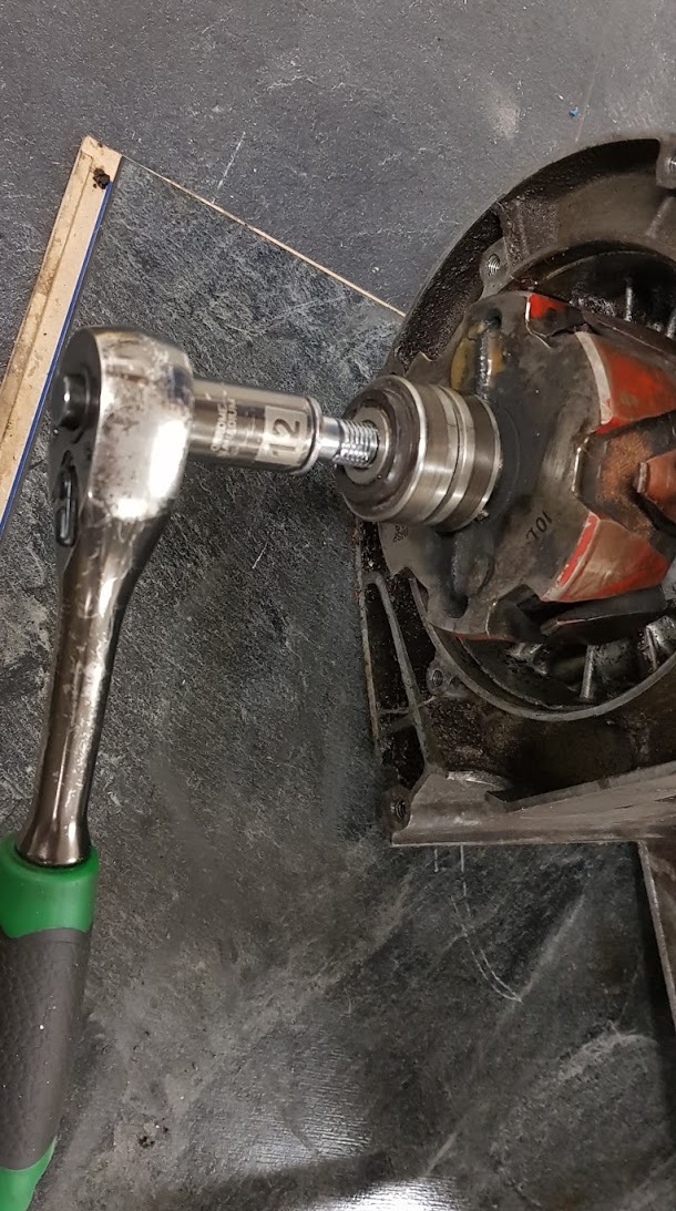
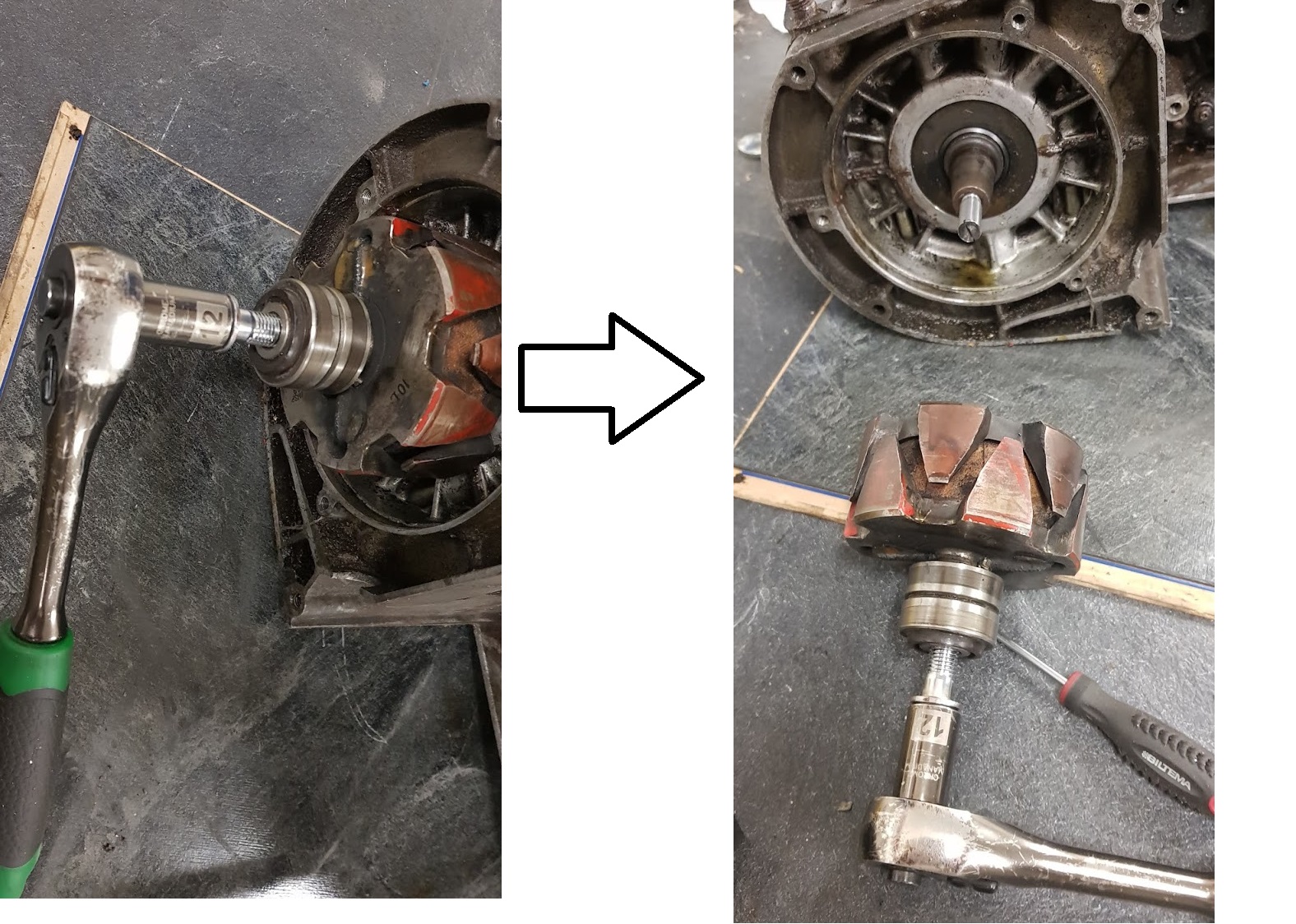
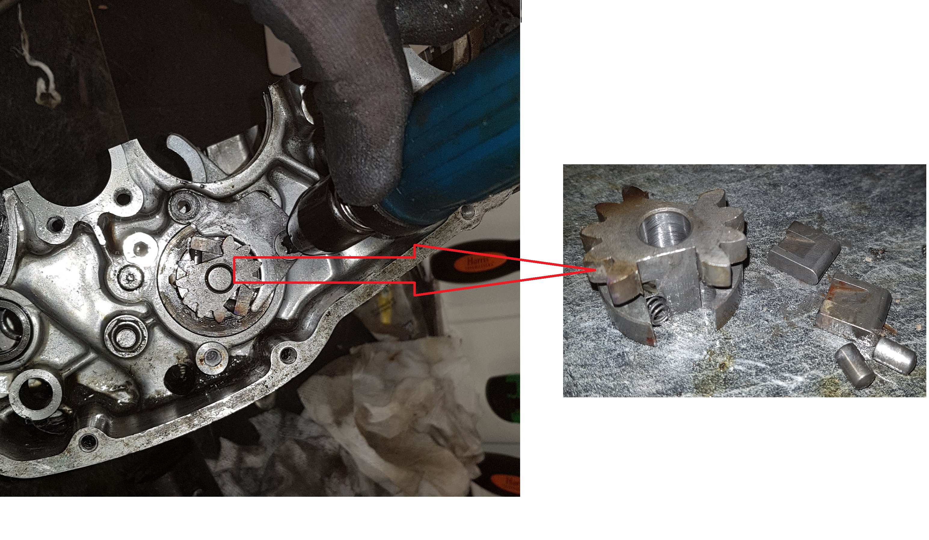
Step 6, rotor removal:
Remove the 8mm axle holding the rotor in place.
Suzuki recommend in the service manual to use a special tool to pull off the rotor. I don’t have that tool and made therefore another type of tool using my lathe. I have also heard some concerns about the Suzuki tool causing damages on the 8mm threads at the end of the crank. Using an 8mm insert as shown in the picture might therefore be a better option.
Any inserts can be used as long as they have 8mm threads.
The bolt to push on the insert causing the rotor to be pulled off must be 10mm fine pitch. I took one of the bolts made for the GT750 exhaust clamping at the rear.
And off it goes 🙂
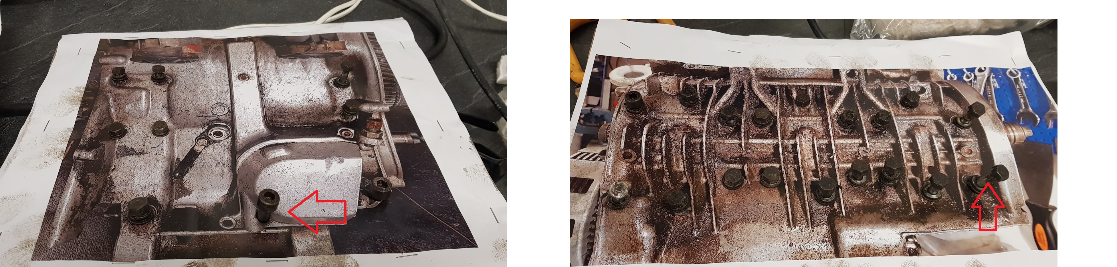
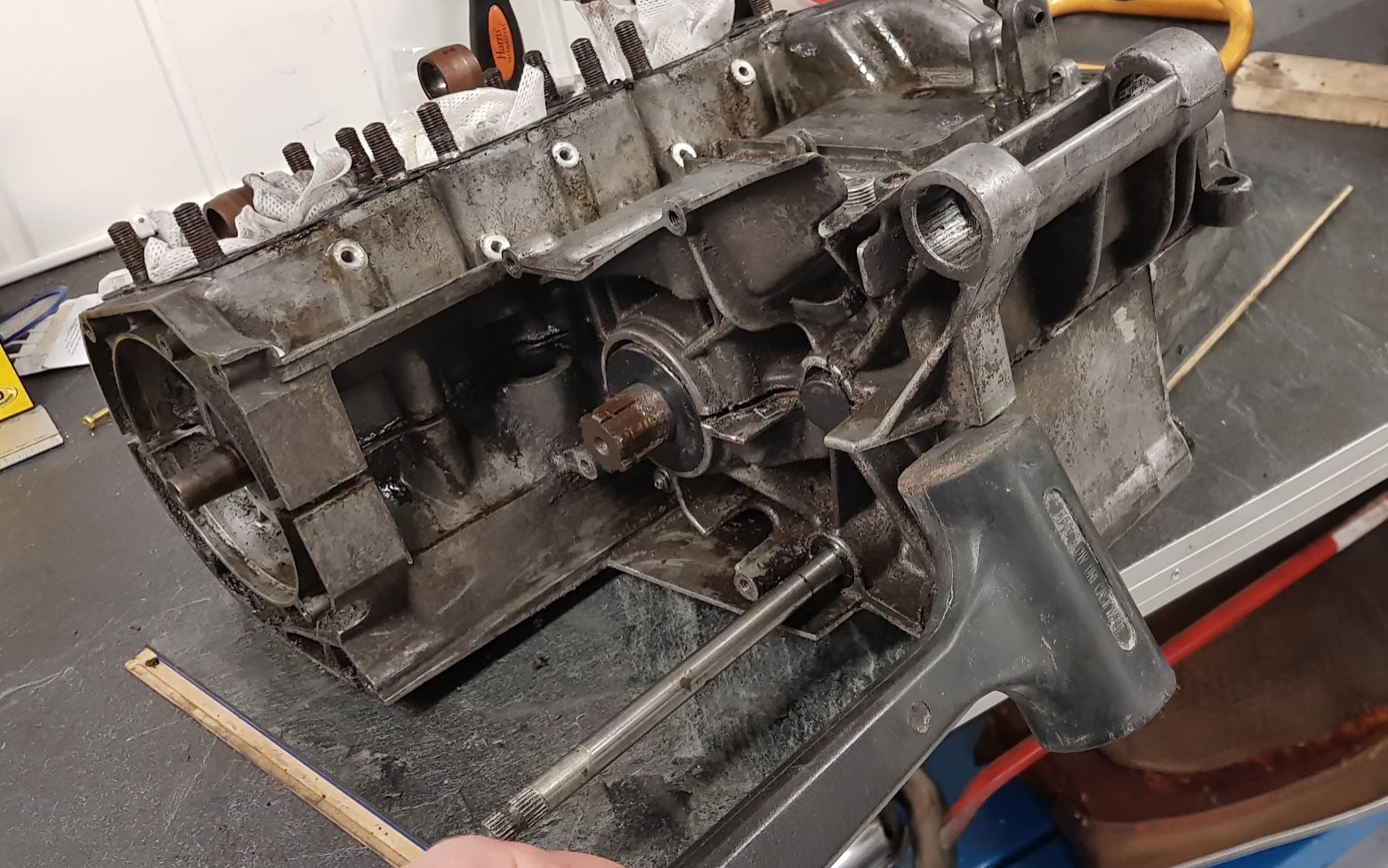
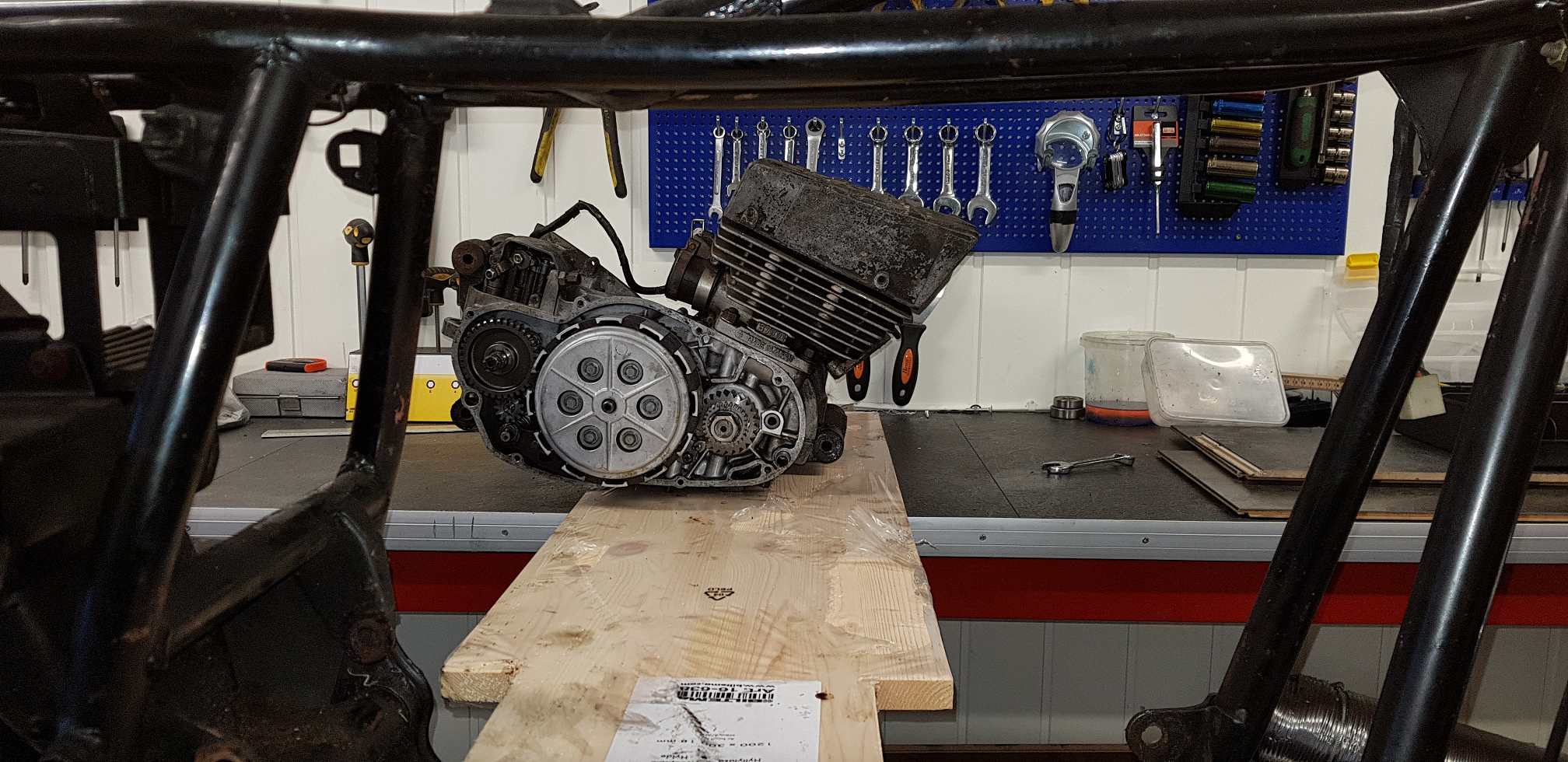
Step 6, splitting the crankcase:
As always, it’s a good idea to store all removed bolts on a cardboard, a simple drawing showing the placements. Since we have entered 2019 I took it one step further and printed out an image of the top and bottom side and stamped it to the cardboard plate. Easy to keep track of all the bolts.
9 bolts on the top side and 18 on the bottom side.
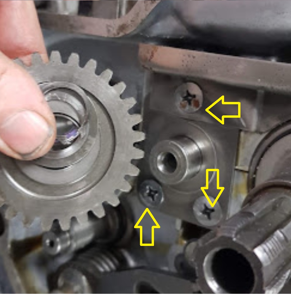
Important : In addition to the bolts on top and bottom you have to remove this three screws since they clamp the top and bottom side together. They are hard to get loose. Probably fastened with loctite glue. I had to use the butane torch and a impact driver. Don’t try without using the impact driver.
A gentle touch using a rubber hammer will get it loose.
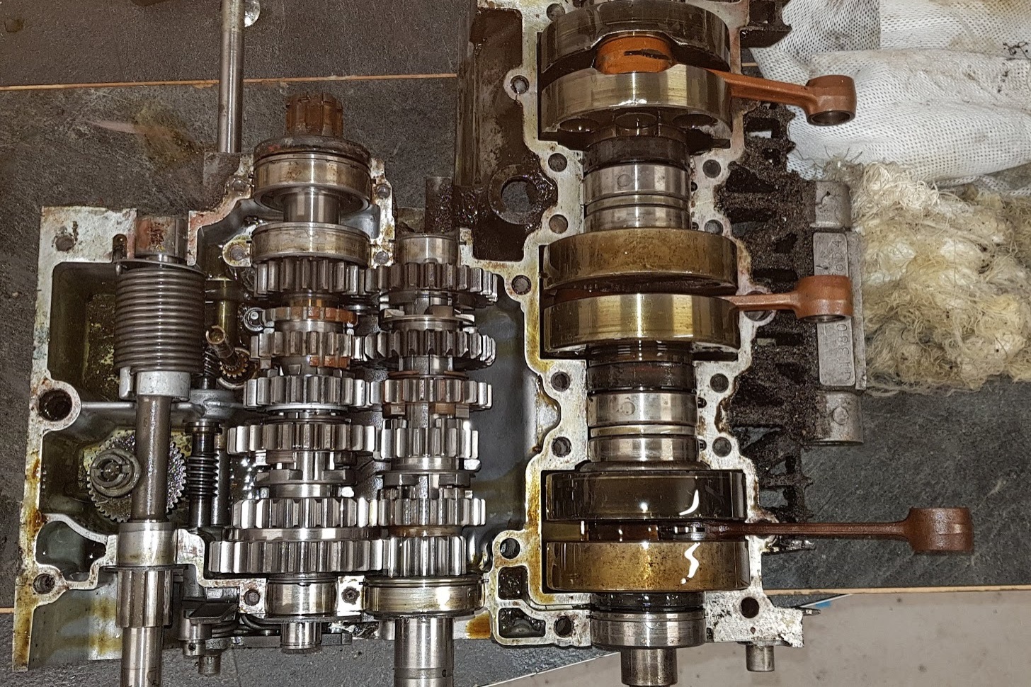
All open…
First impression: could have been worse….
The crank needs rebuilding, but the gears looks good.
Step 7, removing parts:
Again, use the propane/butane torch to heat up and knock on the impactdriver to get the screws loose.
And keep track of the parts.
Take care, the parts will fly away when retracted. Not easy to put together again. I did the same on my GT750 and hopefully it’s all described on my blog how to do it … 🙂
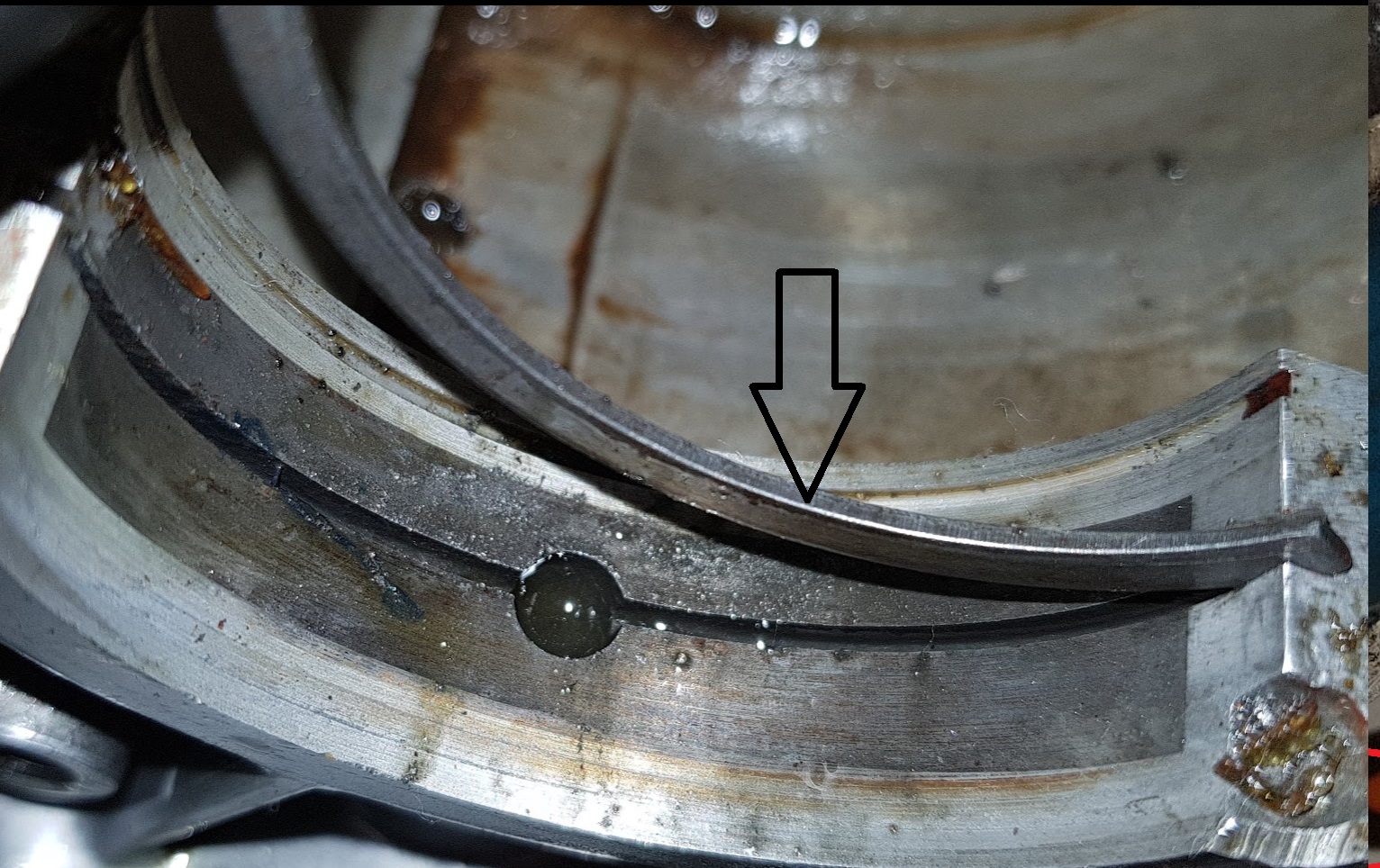
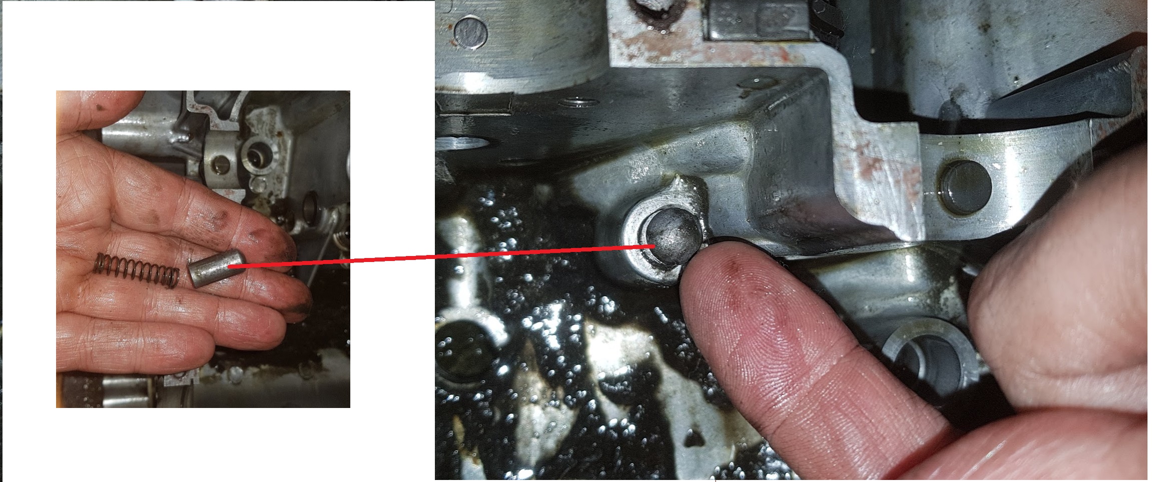
Don’t miss this part while removing the crank.
And this:
Stored in boxes for later inspection.
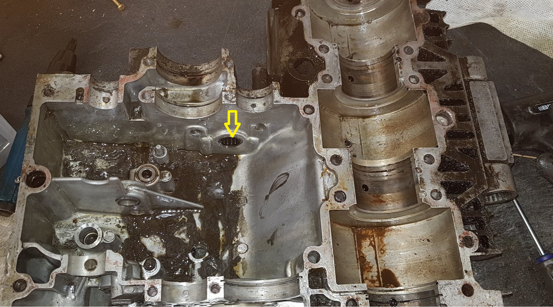
Use a pipe to drive out the needle bearing
After a proper cleaning the crankcase will be powder blasted, but not today.
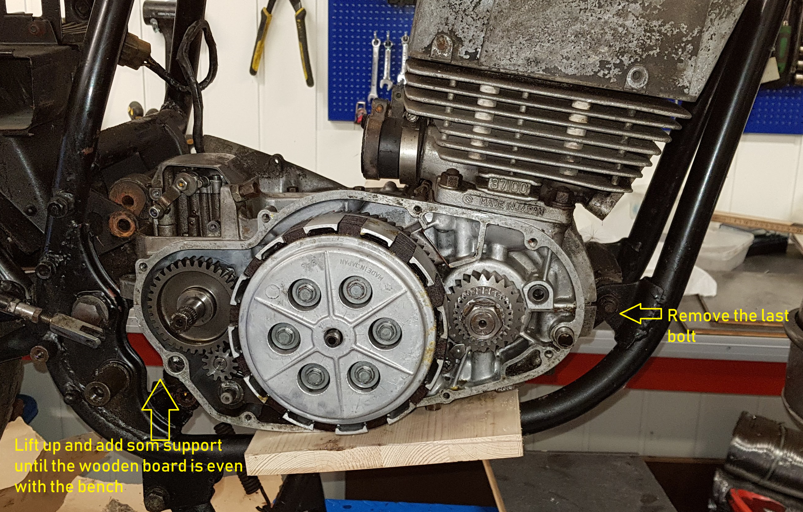
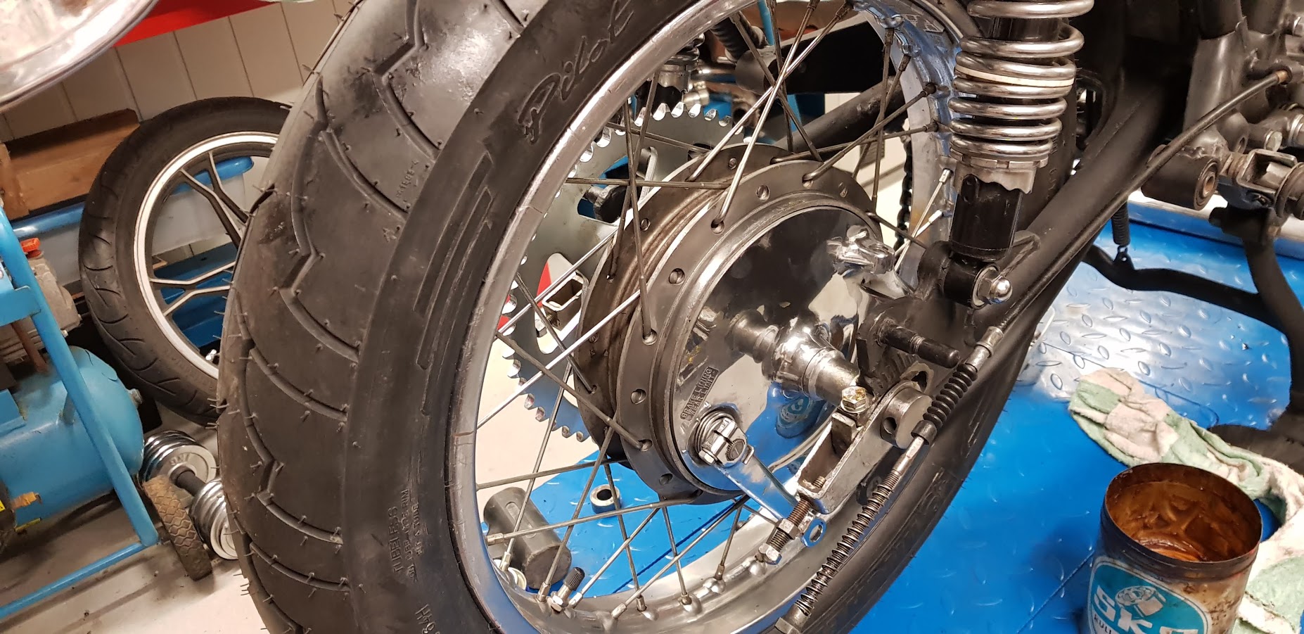
A bit slow progress. Had to make parts on my lathe to be able to fit the rear wheel. Had plans to reuse the spacers from the GS wheel, but nothing was able to fit. Main reason : The GS axle was 17mm and the GT is 20mm.
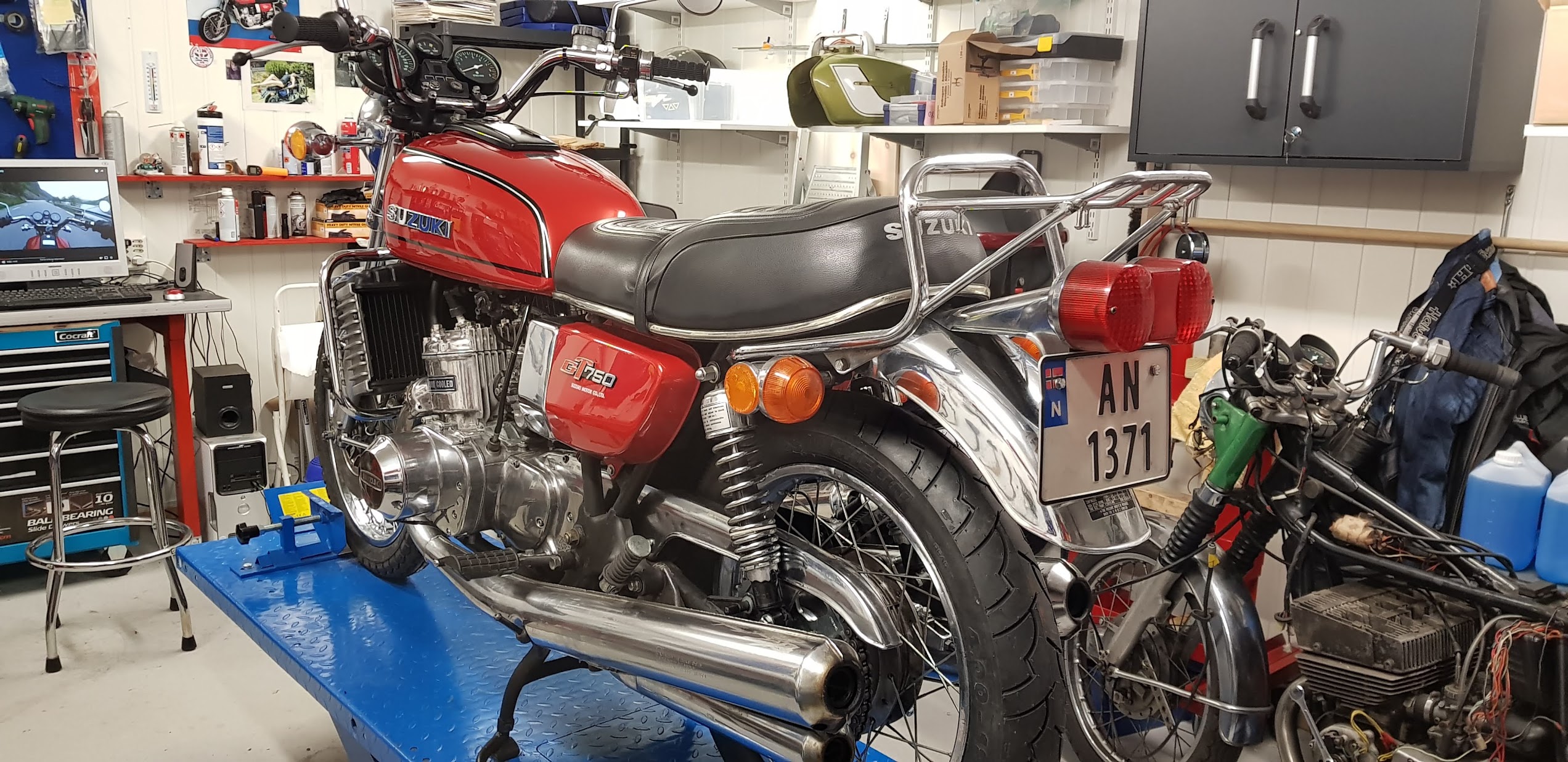
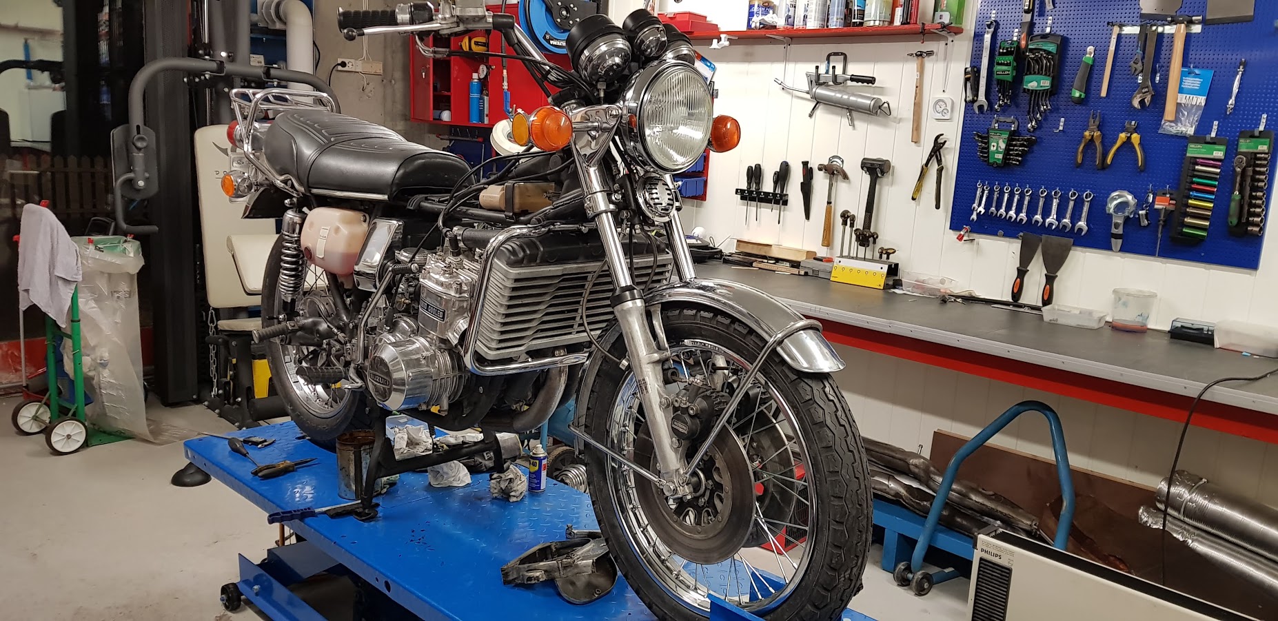
Finally, both wheels are mounted on the bike. 🙂
At last, both wheels are on. GT wheels looks so much better compared to the GS wheels.