Ignition circuitry
The schematics shows the circuitry to ignite all of the spark plugs. This is a copy from the Suzuki service manual.

Fig1.
In the schematics all three points are drawn in a open position. This will never happen. The normal positon is closed and 24 deg before pistons top position (BTDC) the contact breaker (point) will open up if the adjustemen is done correct.
Step 1: Contact breakes are closed.
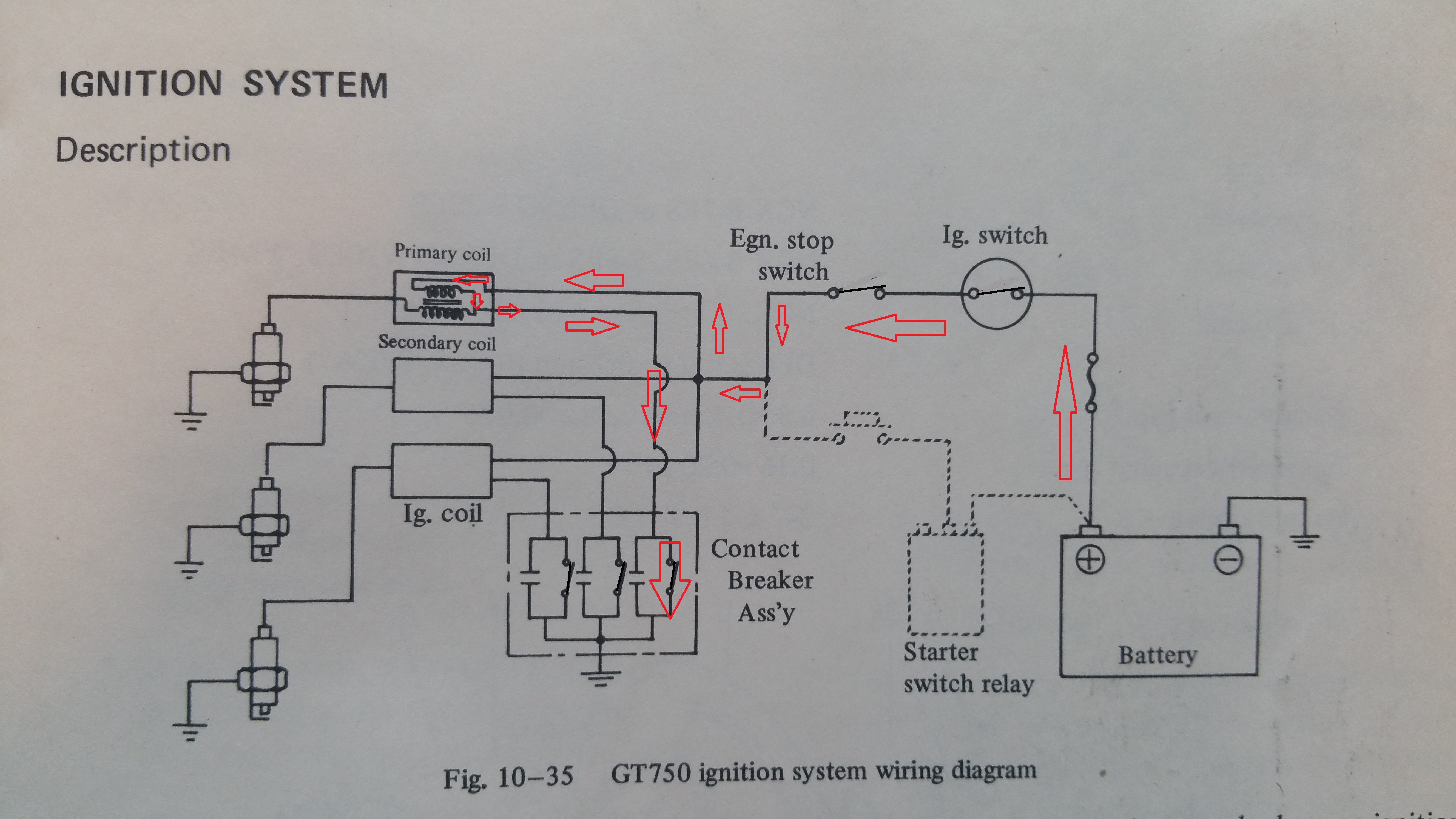
Fig.2
Ig.swich and Egn.stop switch must of course be in closed position to allow current to the coils.
The red arrows in fig.2 shows how the current goes from the battery through the primary coil and down to ground through the contact breaker.The same will happen in the others coils as long as the corresponding contackt breaker is closed.
This is the reason why you drain the battery empty quite soon if you leave the ignition switch on while parking. A lot of current are going through the coils.
Step 2, Ignition
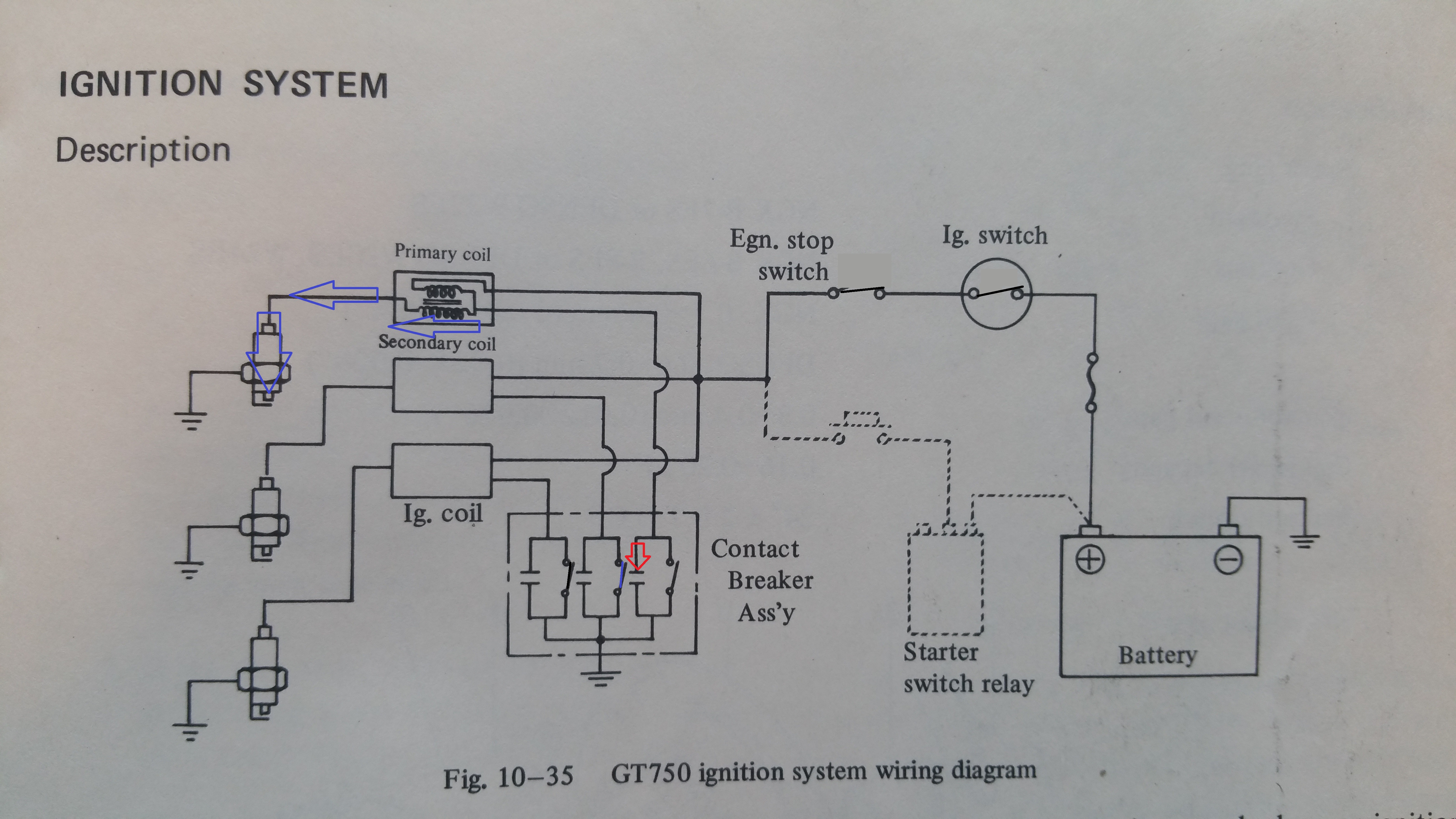
Fig.3
When the piston comes to the BTDC ( 24 deg before the top, 3,64mm on left and right cylinder and 3,42mm on the centre cylinder ) the contact braker open and cut off the current into the coil.
The next step is not easy to understand, but I will try to explain. Before the current was cut off it made a powerful magnetic field in the coil. When the field collapse (due to the opening of the contact breaker and cutting off the current) the change in the magnetic field will make a voltage induction many times higher than the 12V battery in the bike. This high voltage will also burn the points in the contact breaker if there where no capacitor connected in paralell. The capacitor will be recharged by this voltage and store the energy for a short perode of time. At the same time the primary side of the coil will also see the switching of the magnetic field. The primary coil has more windings compare to the secondary and therefore transform the voltage to many thousand volts and we get the spark. See the blue arrows in fig. 3
The basic functions of coils and capacitors will be explained more in depth in a separete post.
The physical implementation and the adjustment procedure for the timing will also be explained in a separate post.