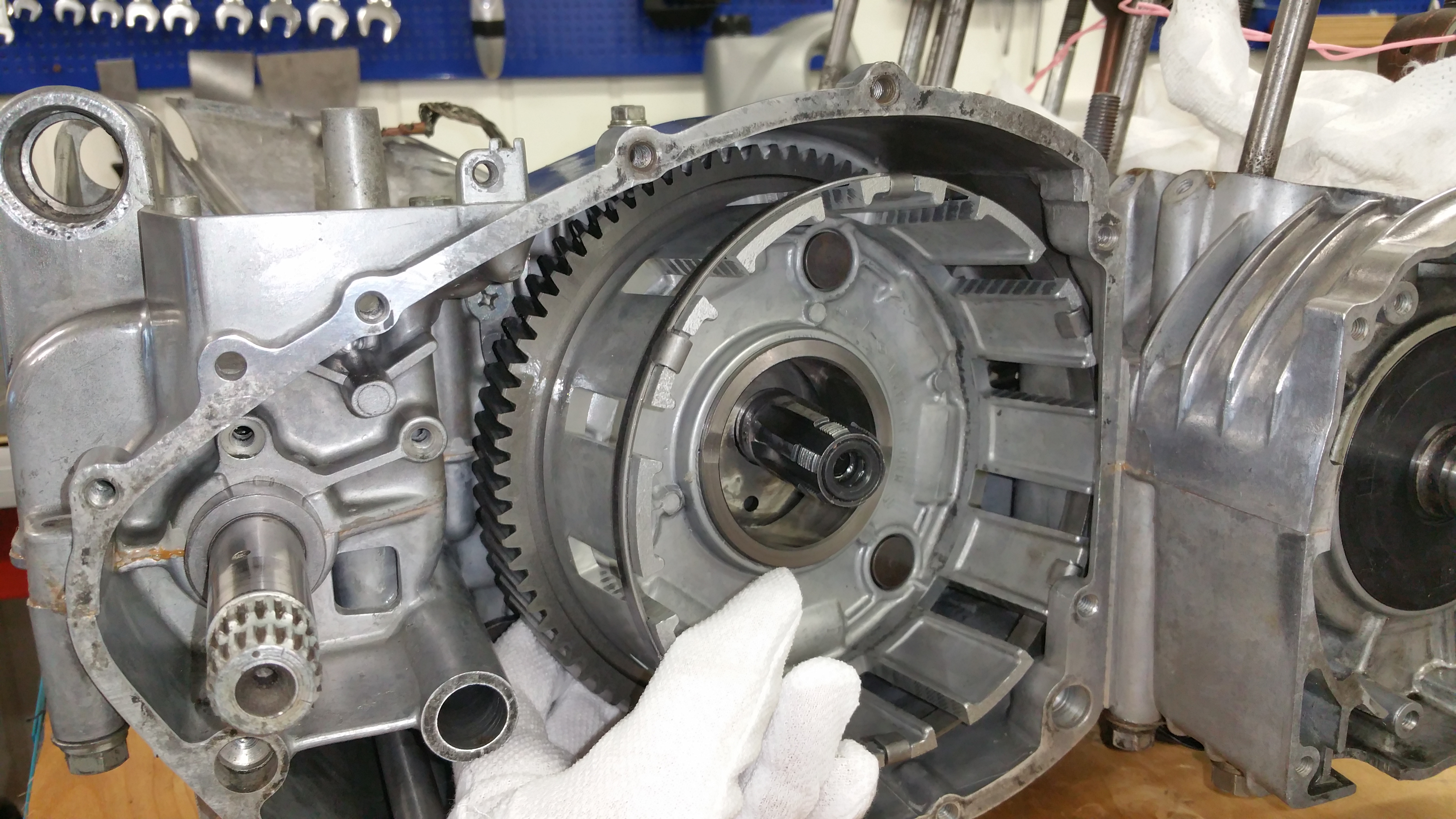
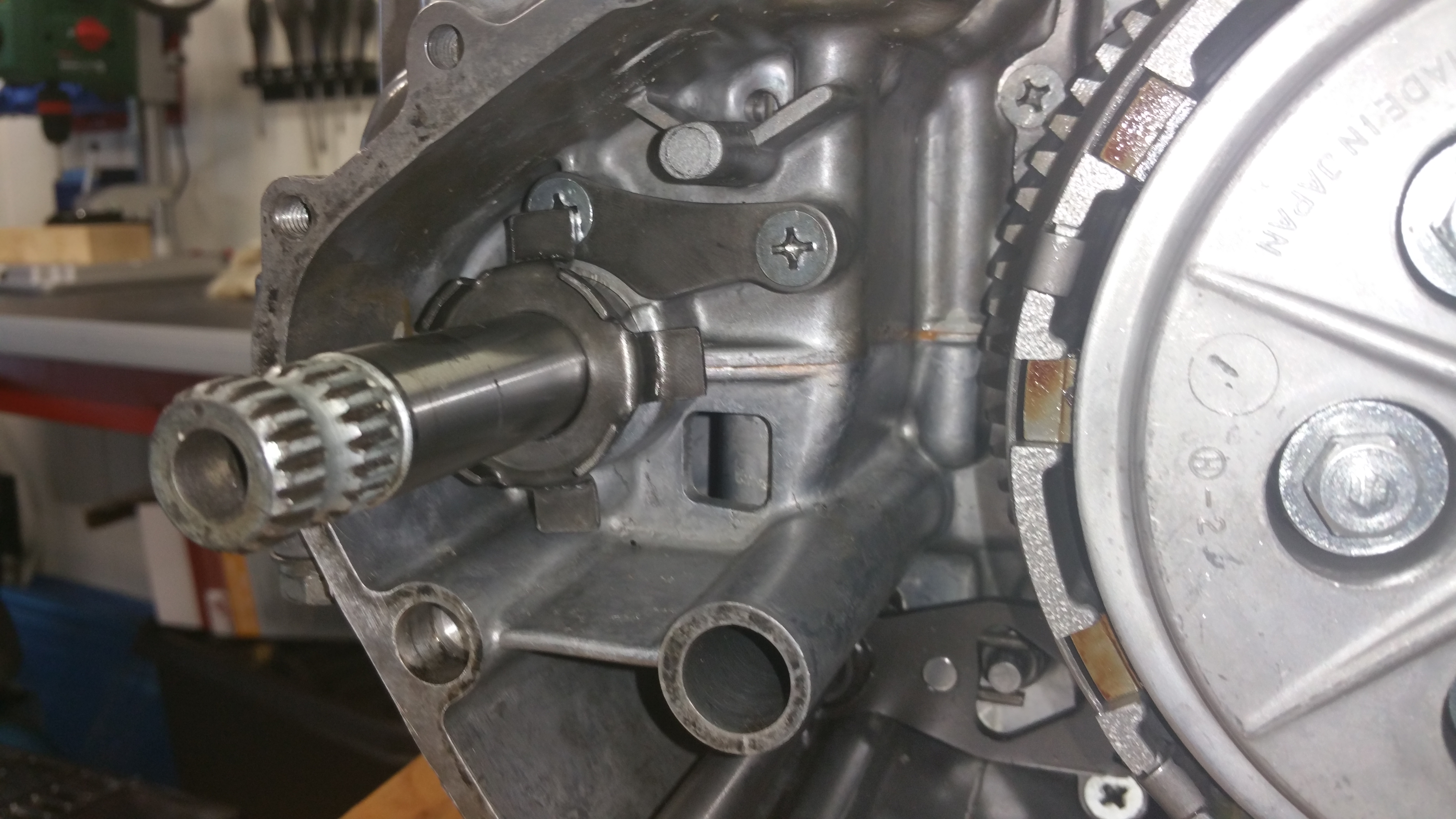
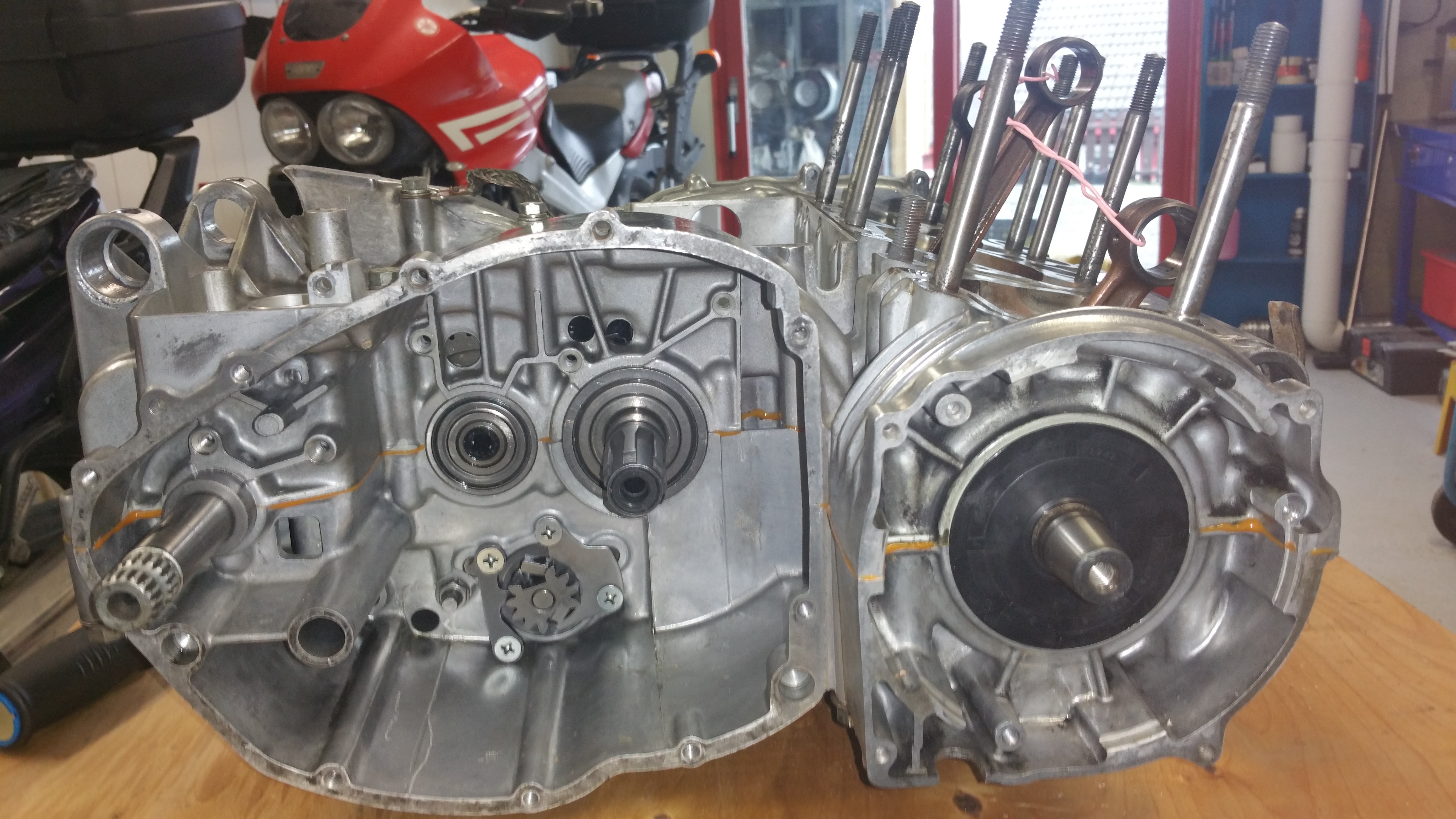
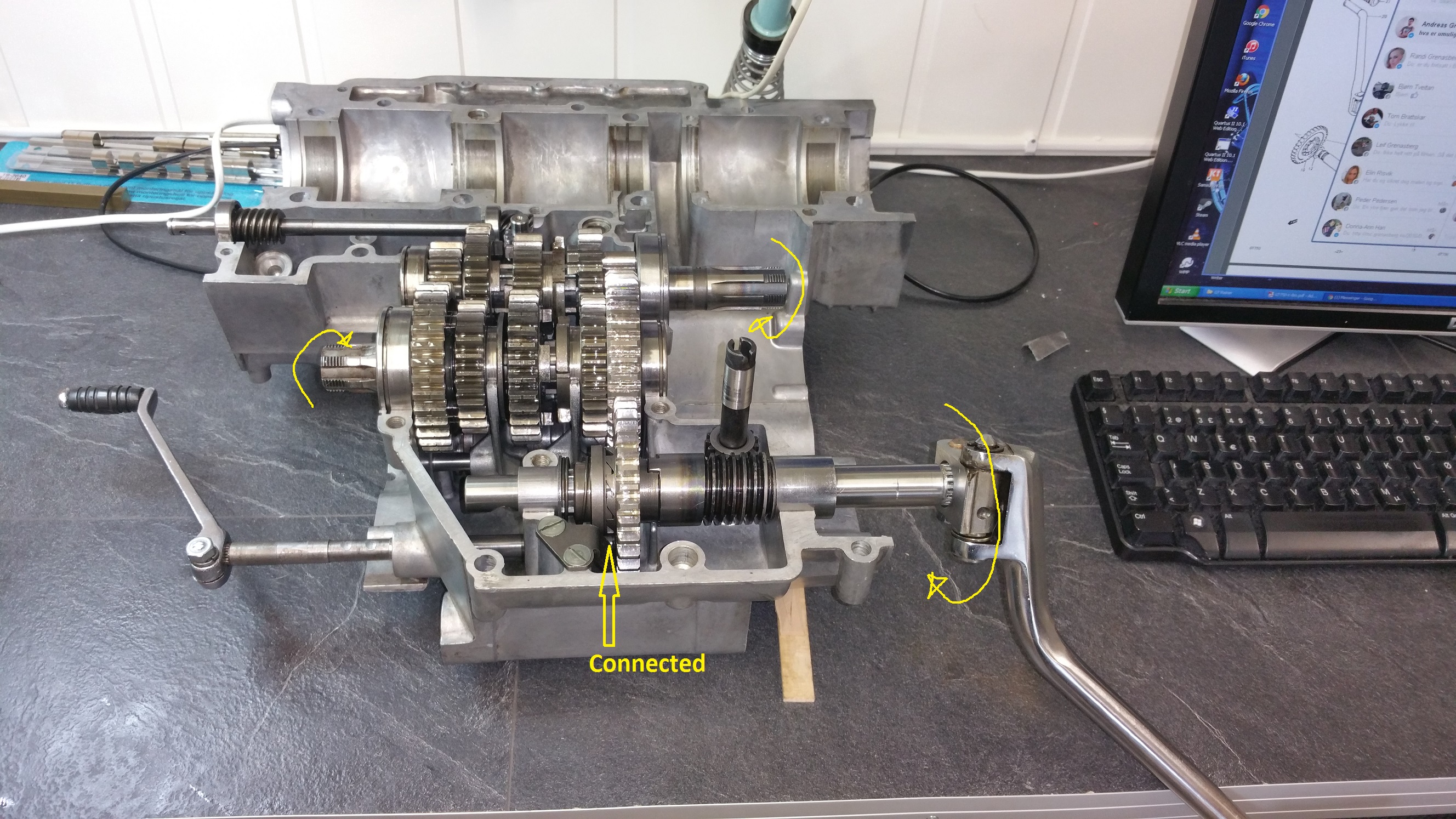
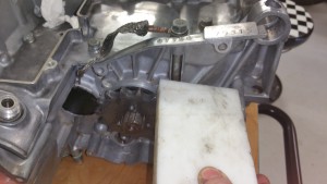
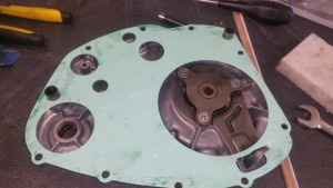
The photo below shows how I did the assembly of the clutch and the kick starter.
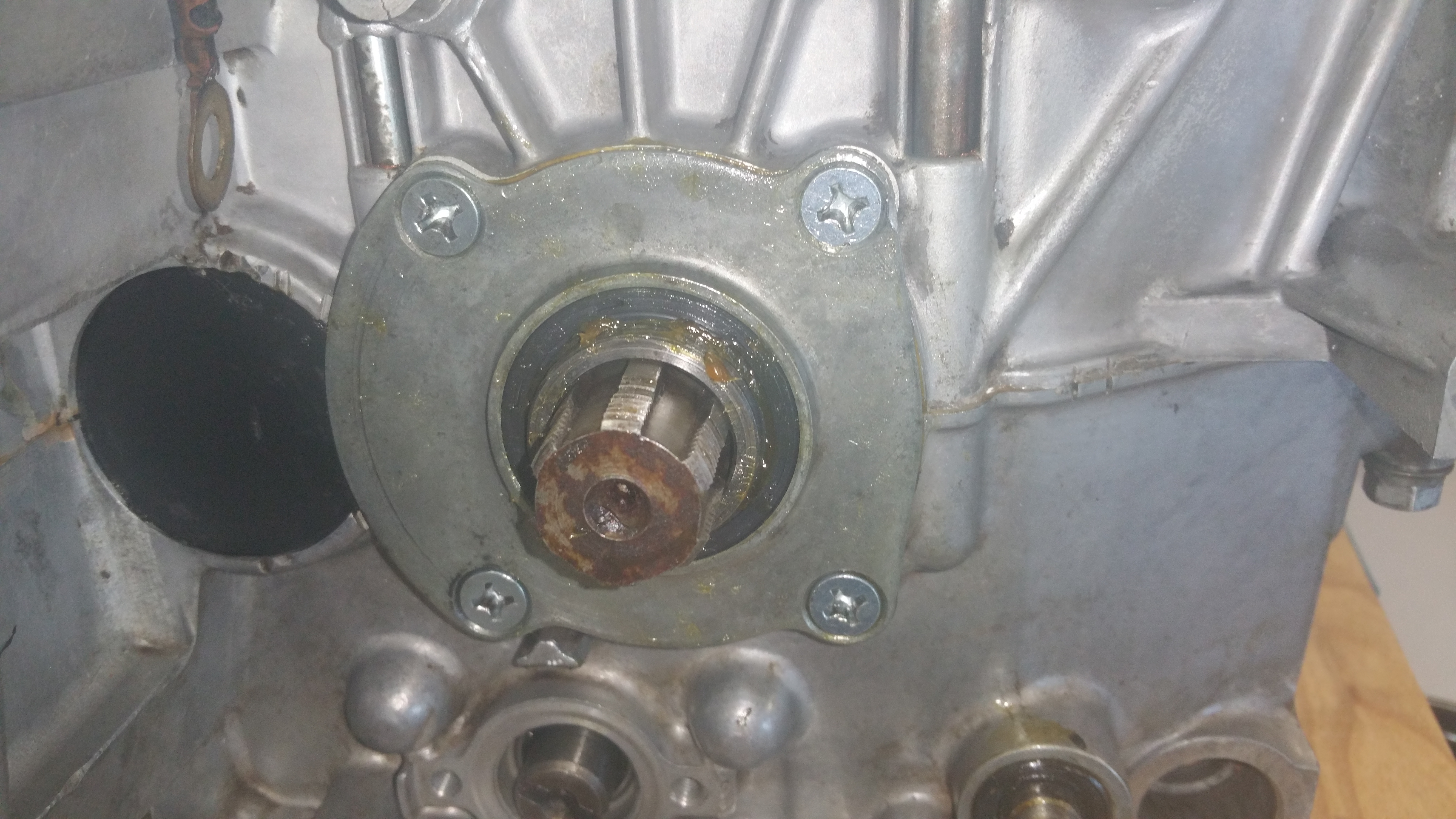
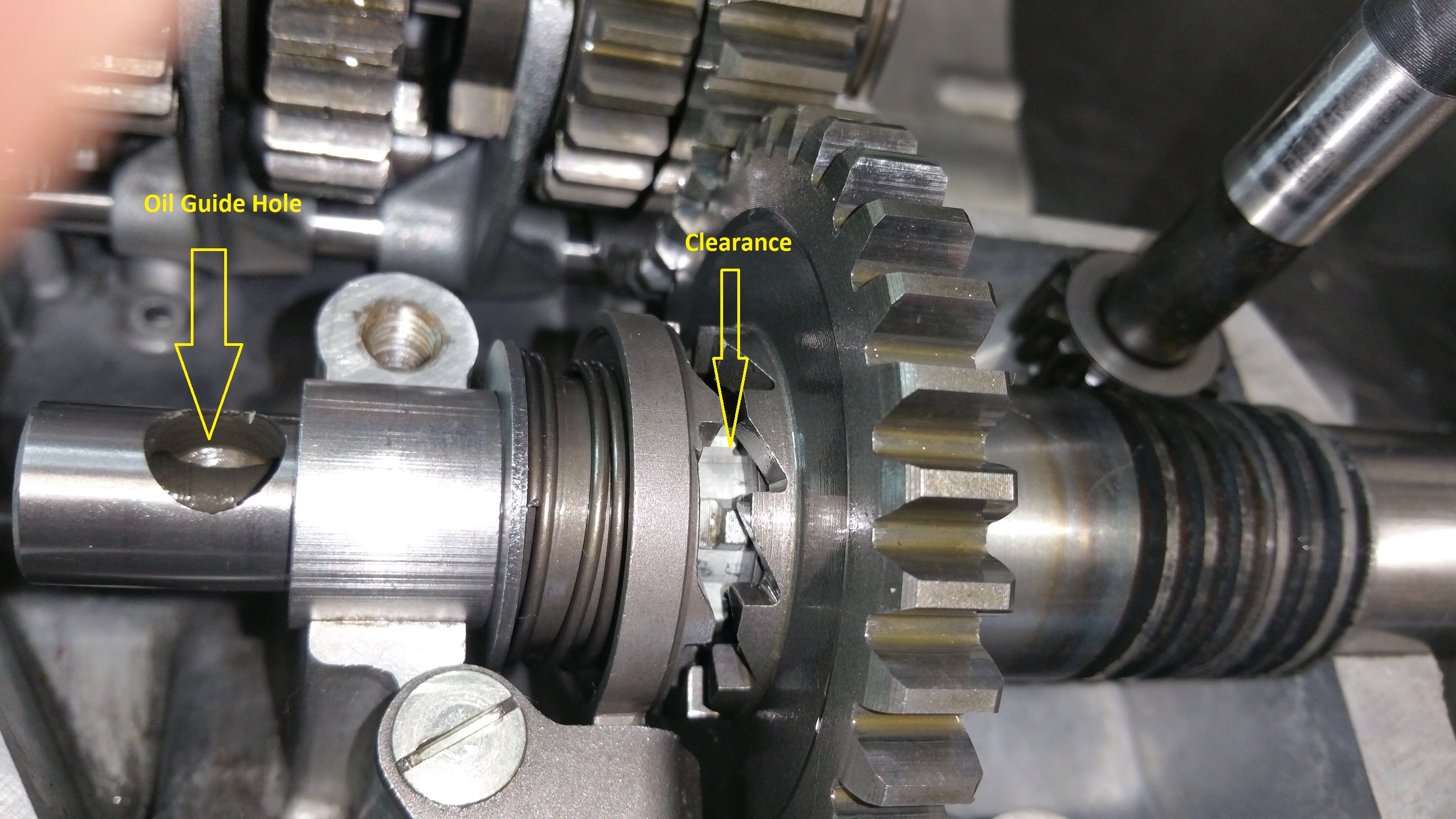
Step 1: Fit the oil guide plate. Drive all three screws well home. If you are to use thread locker or not depends on your religion. Do you believe in it or not. Someone says ” don’t use it, you will never get them loose”. Others say….And I’m not gonna tell you what I did .
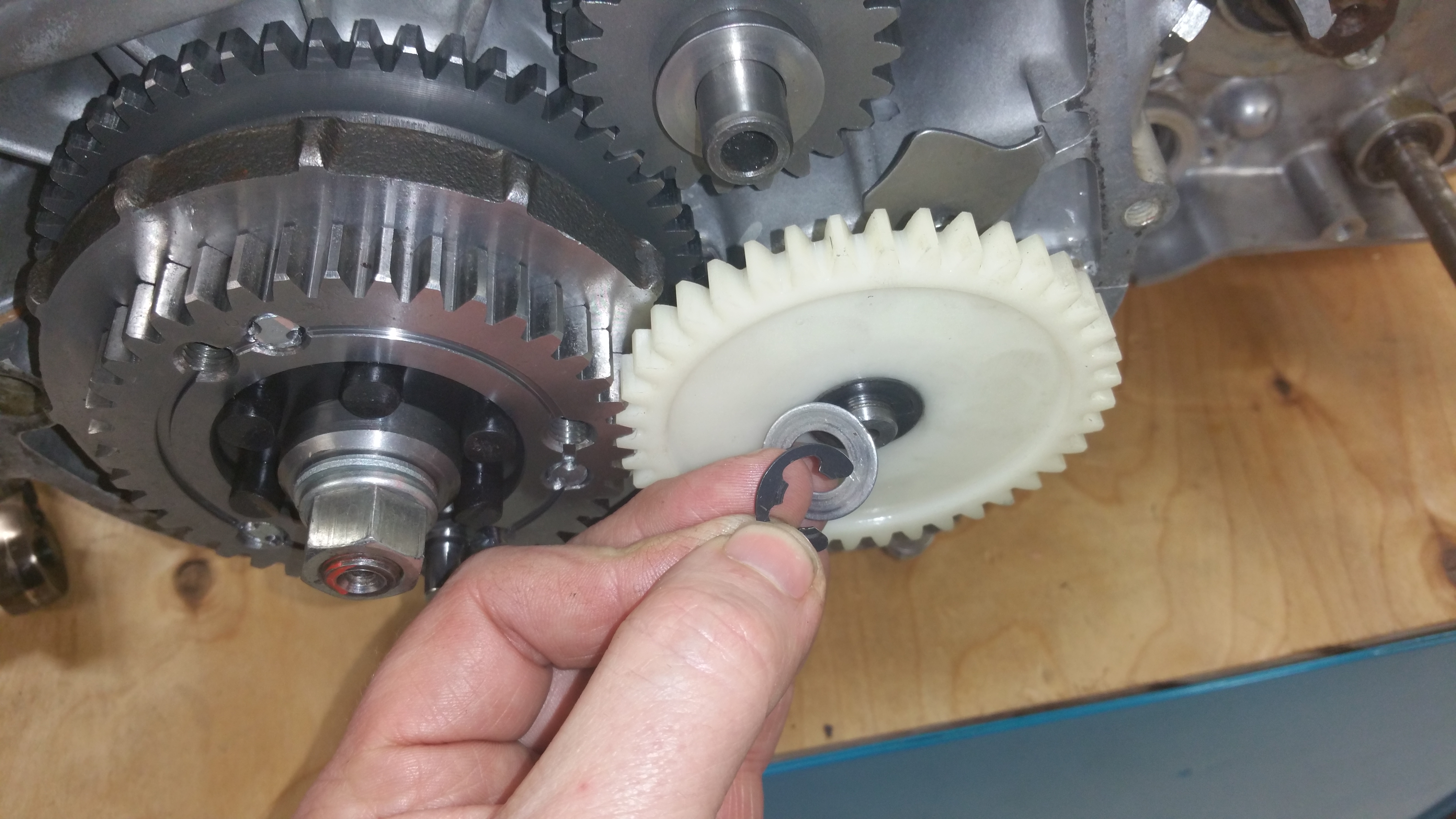
Step 2:
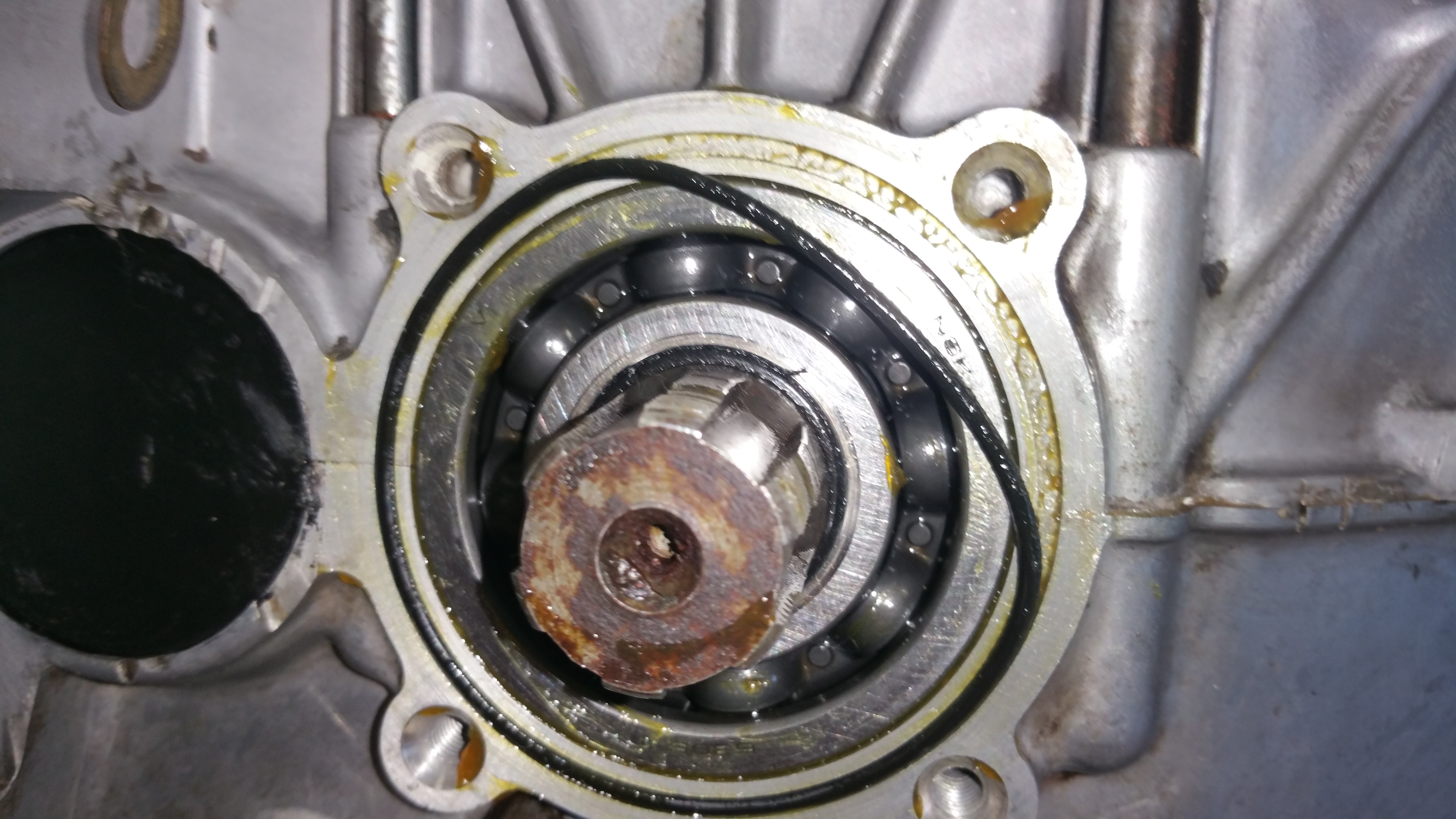
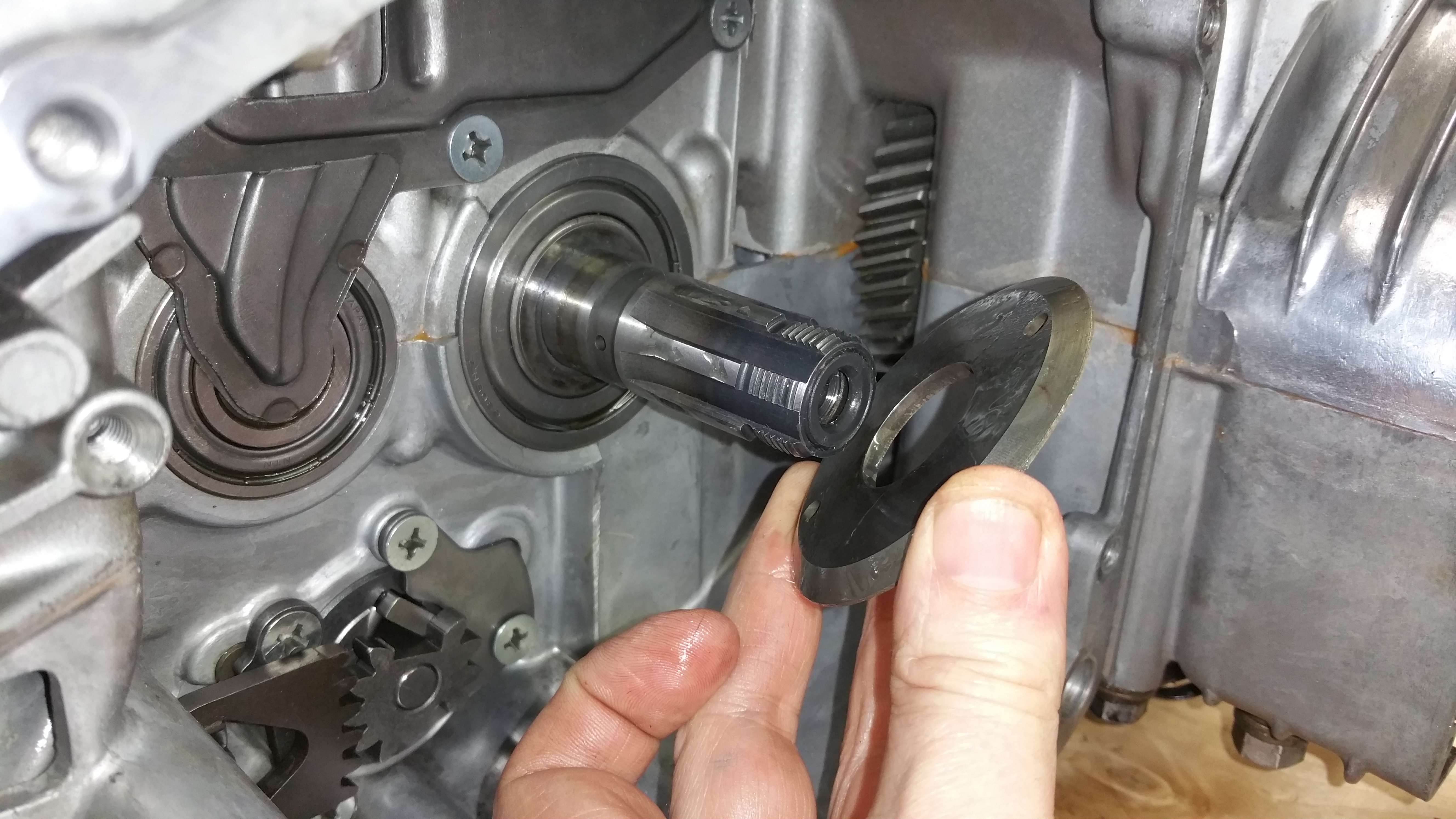
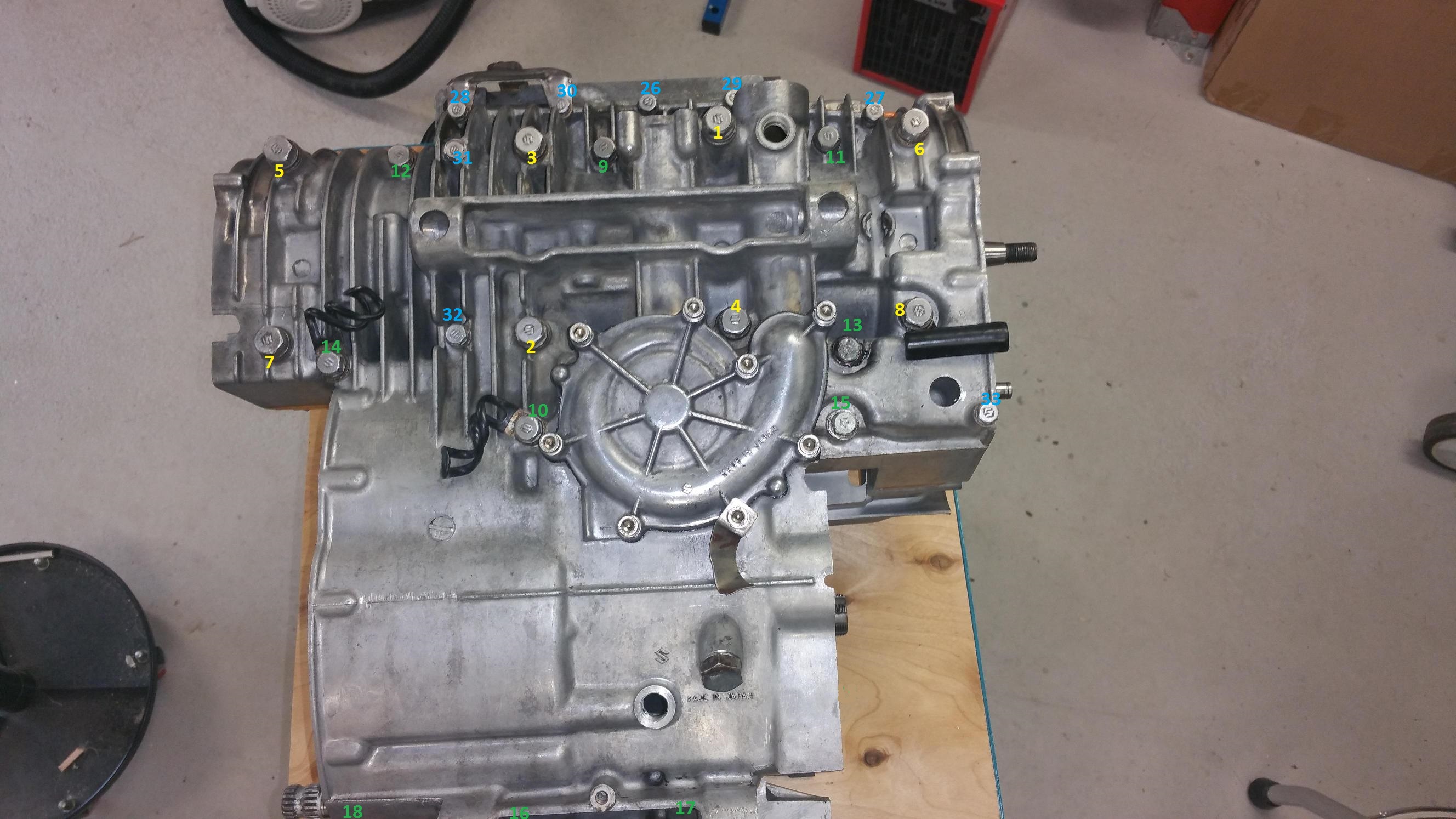
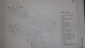
Mount the shim ( no.16)
Step 3:
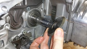
Mount the spacer, chamfer side goes in back.
Step 4:

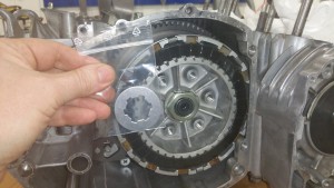
Mount the clutch
Step 5:

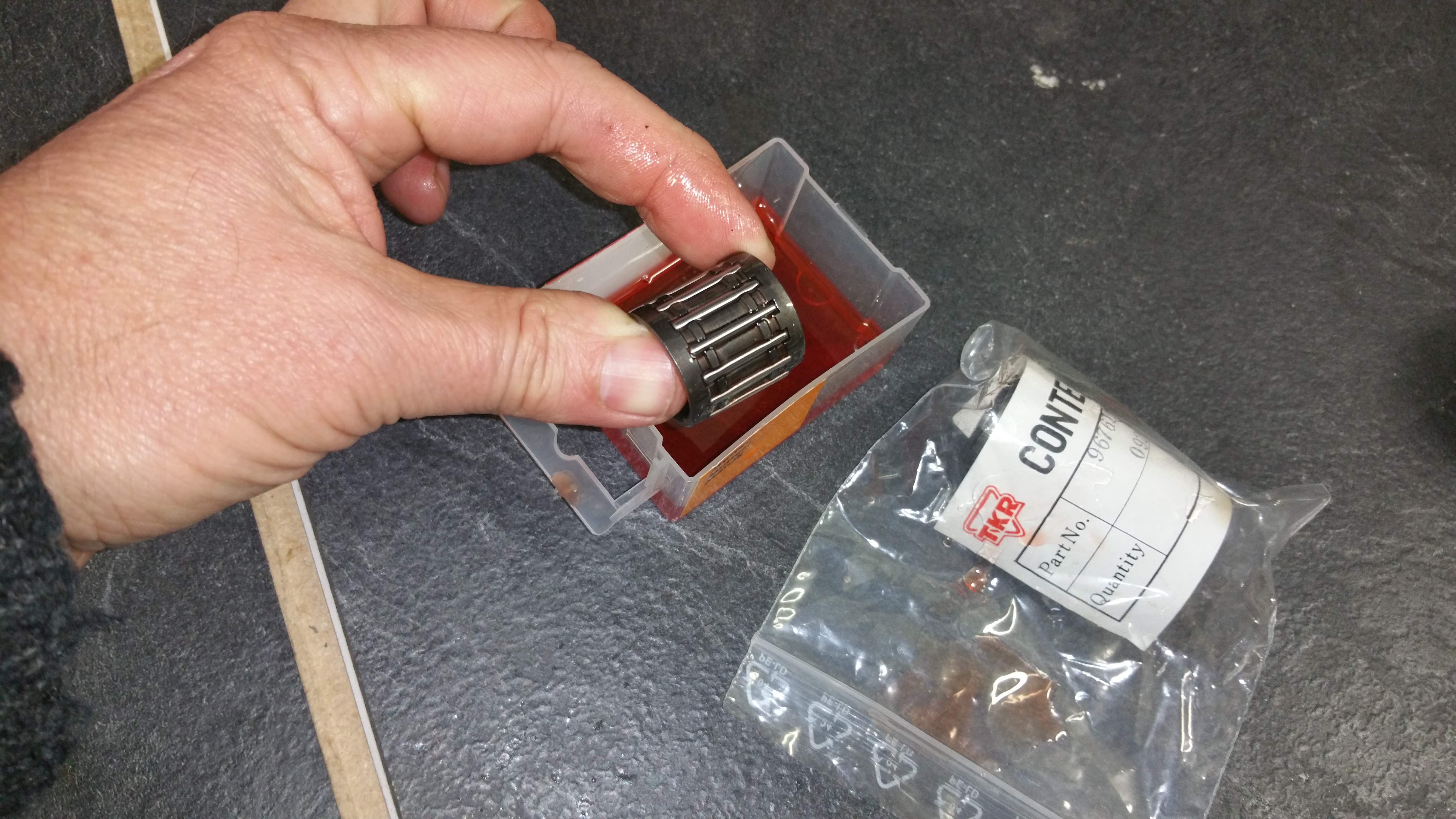
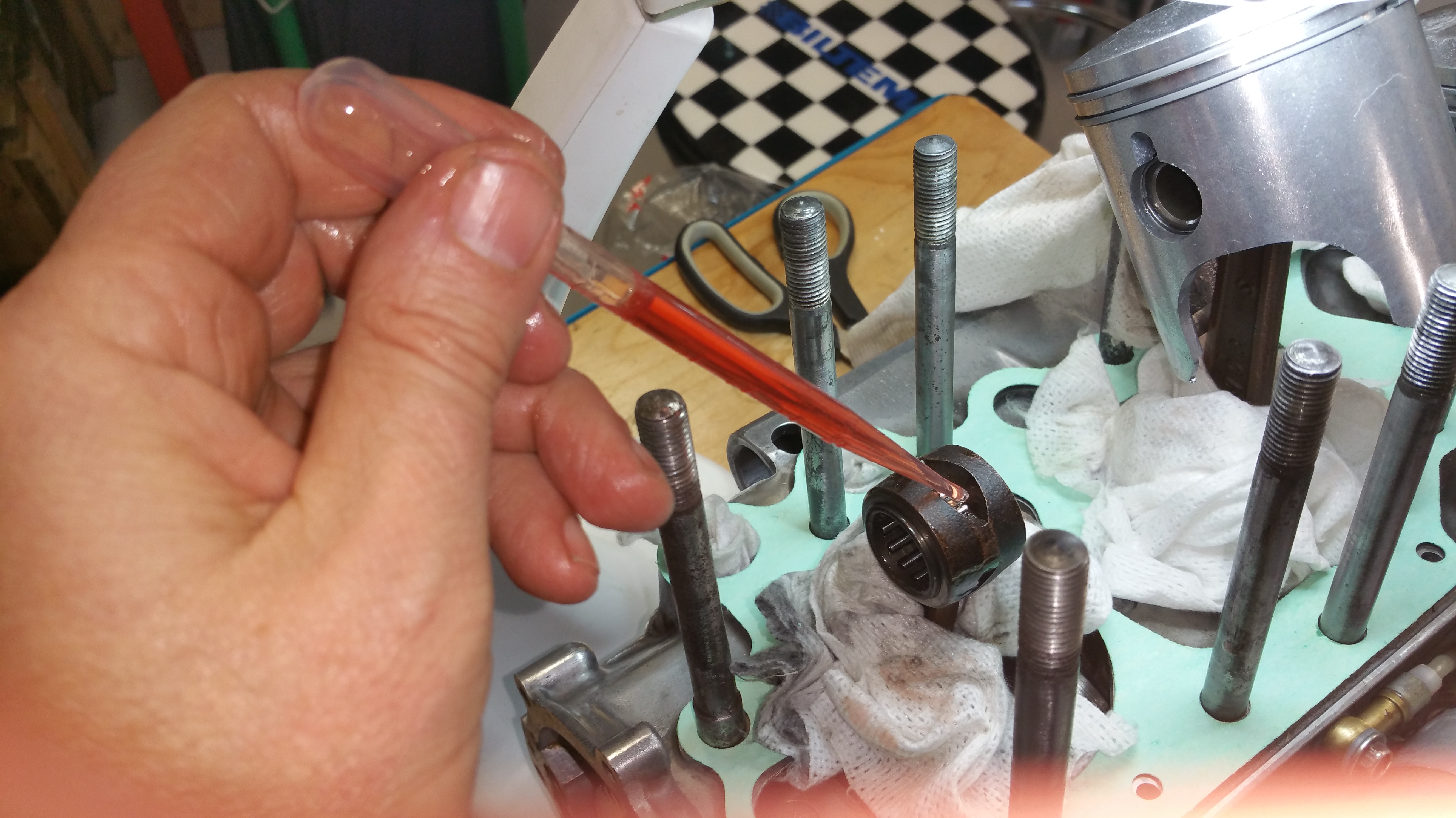
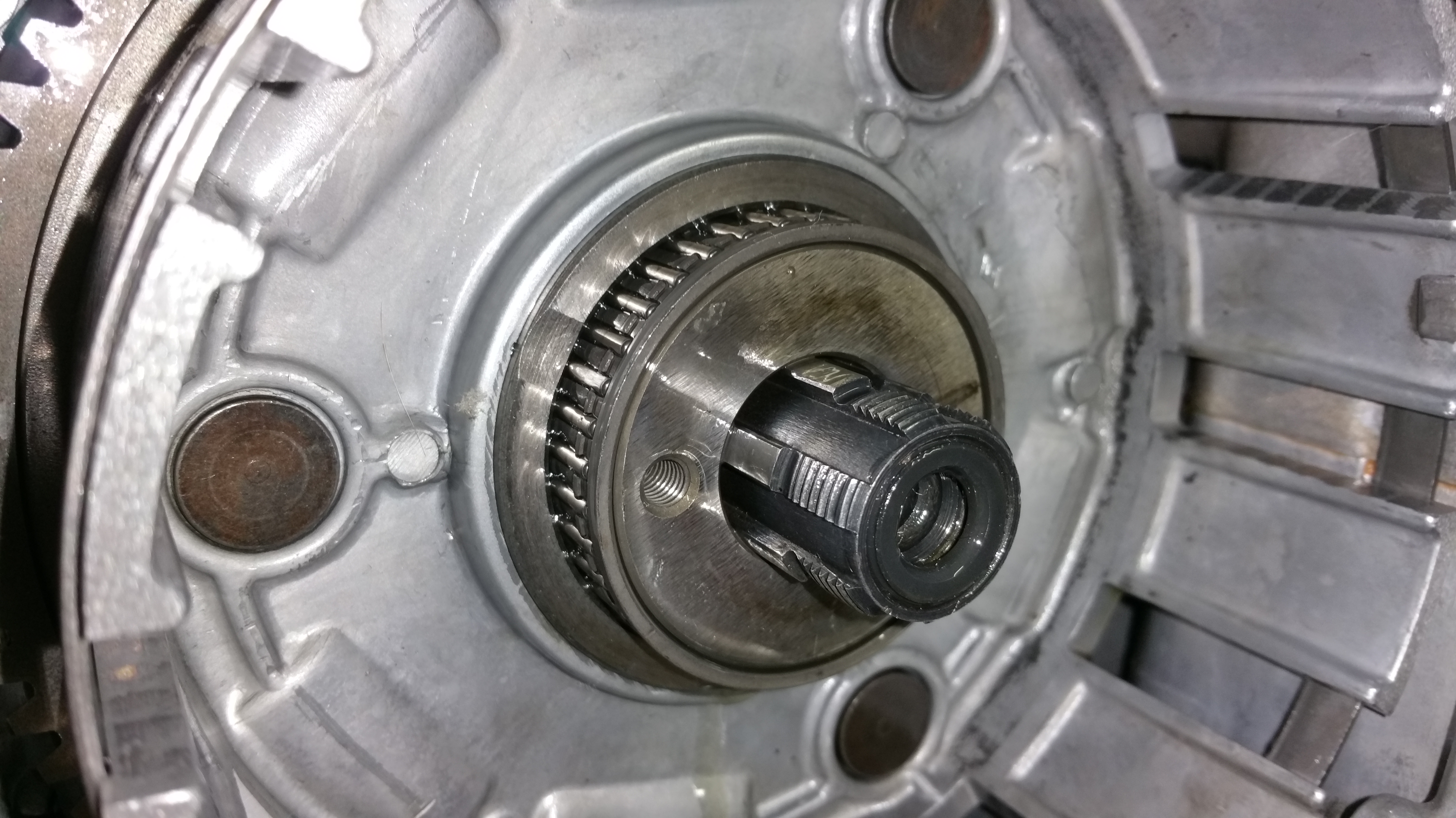
Mount the bearing assembly
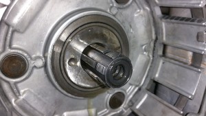
Step 6:
Mount the spacer, chamfer side at the front.
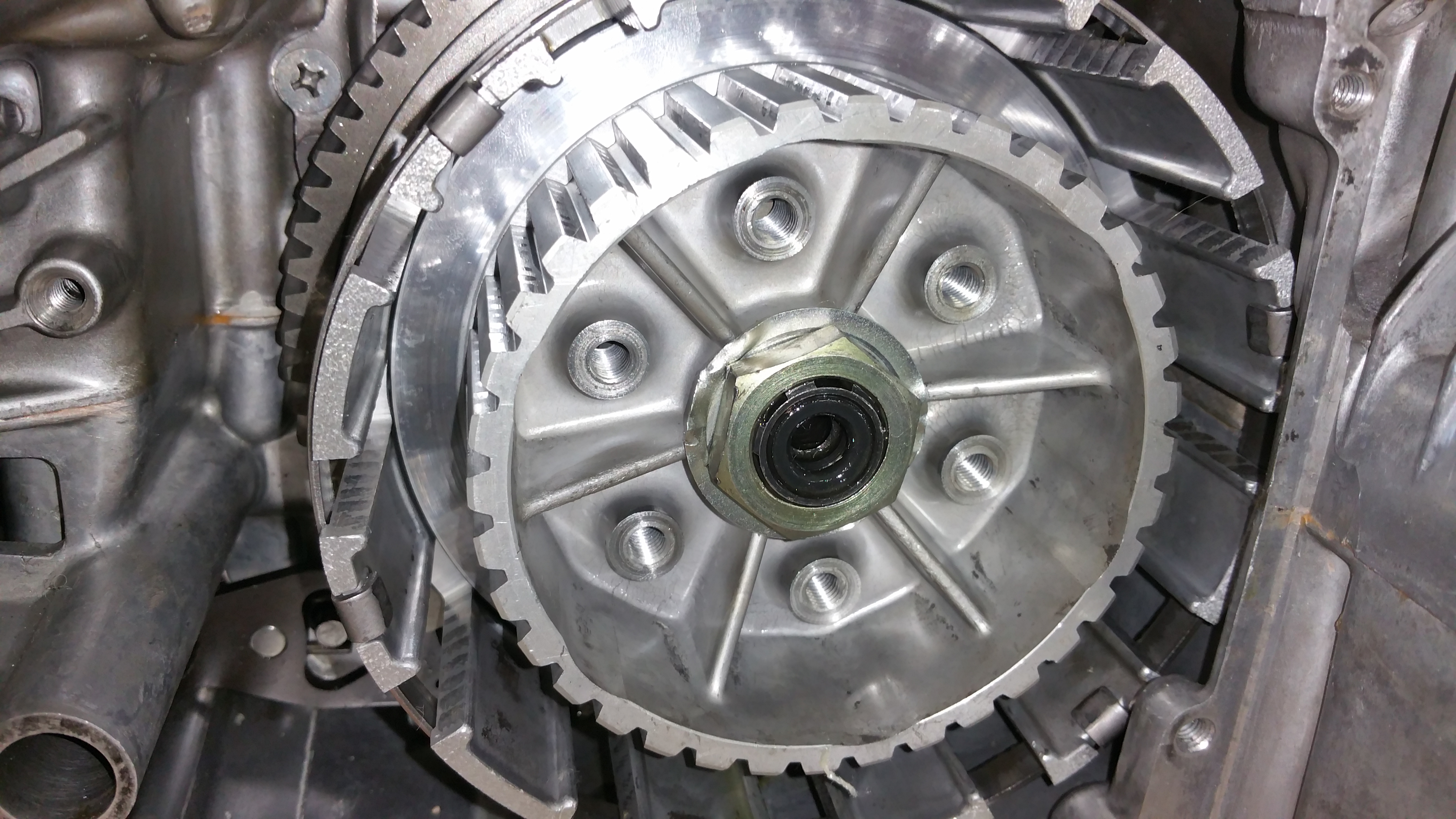
Step 7:
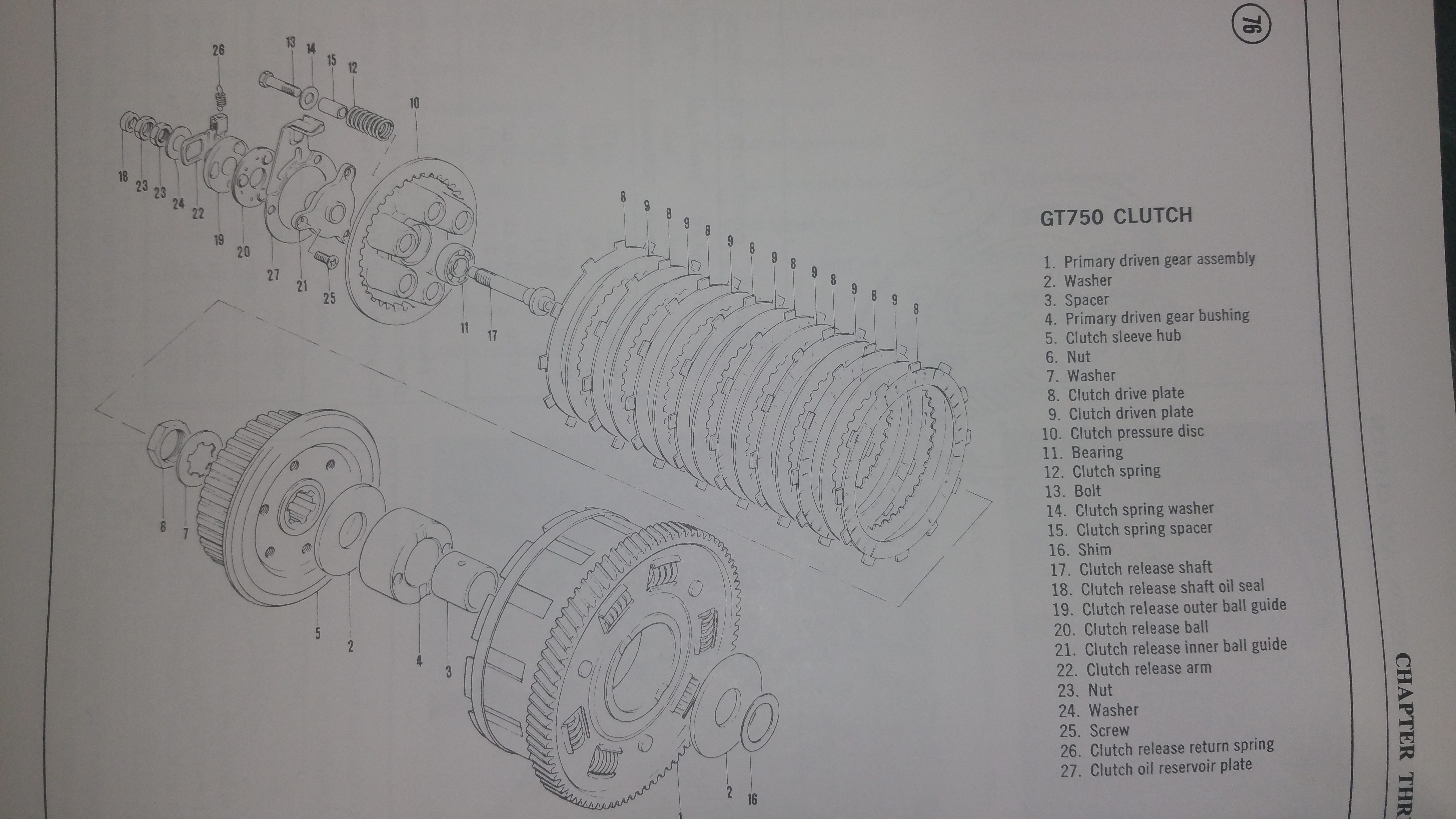
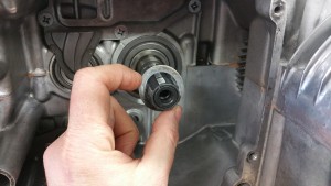
Mount the clutch sleeve hub (5), locking washer (7) and center nut (6)
Always use a new locking washer, not the old one like I did on the photo.Why did I use the old one ? I didn’t know I had a new one until I had completed the assembly process. Can save the washer for the next time.
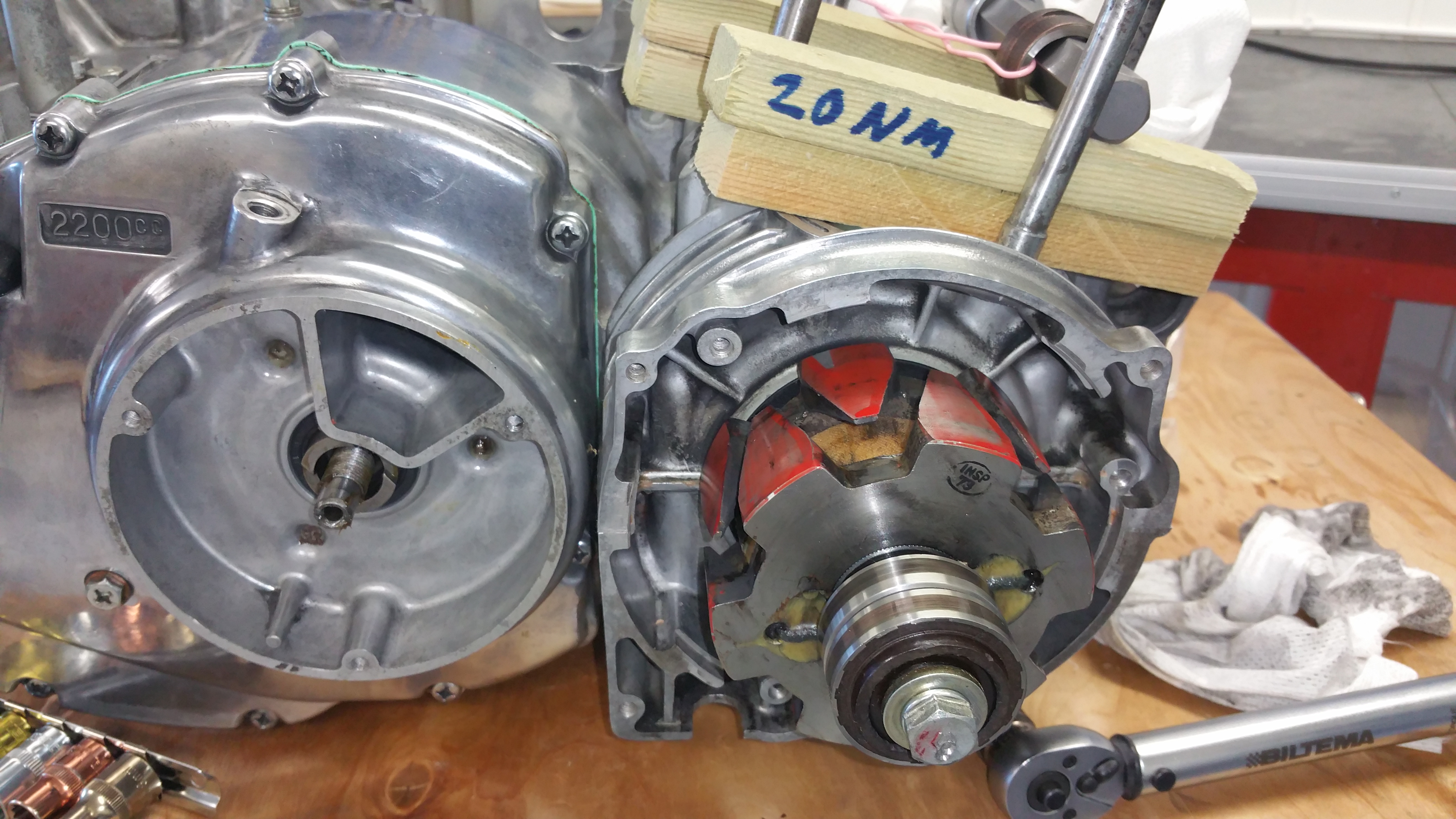
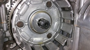
Step 8:
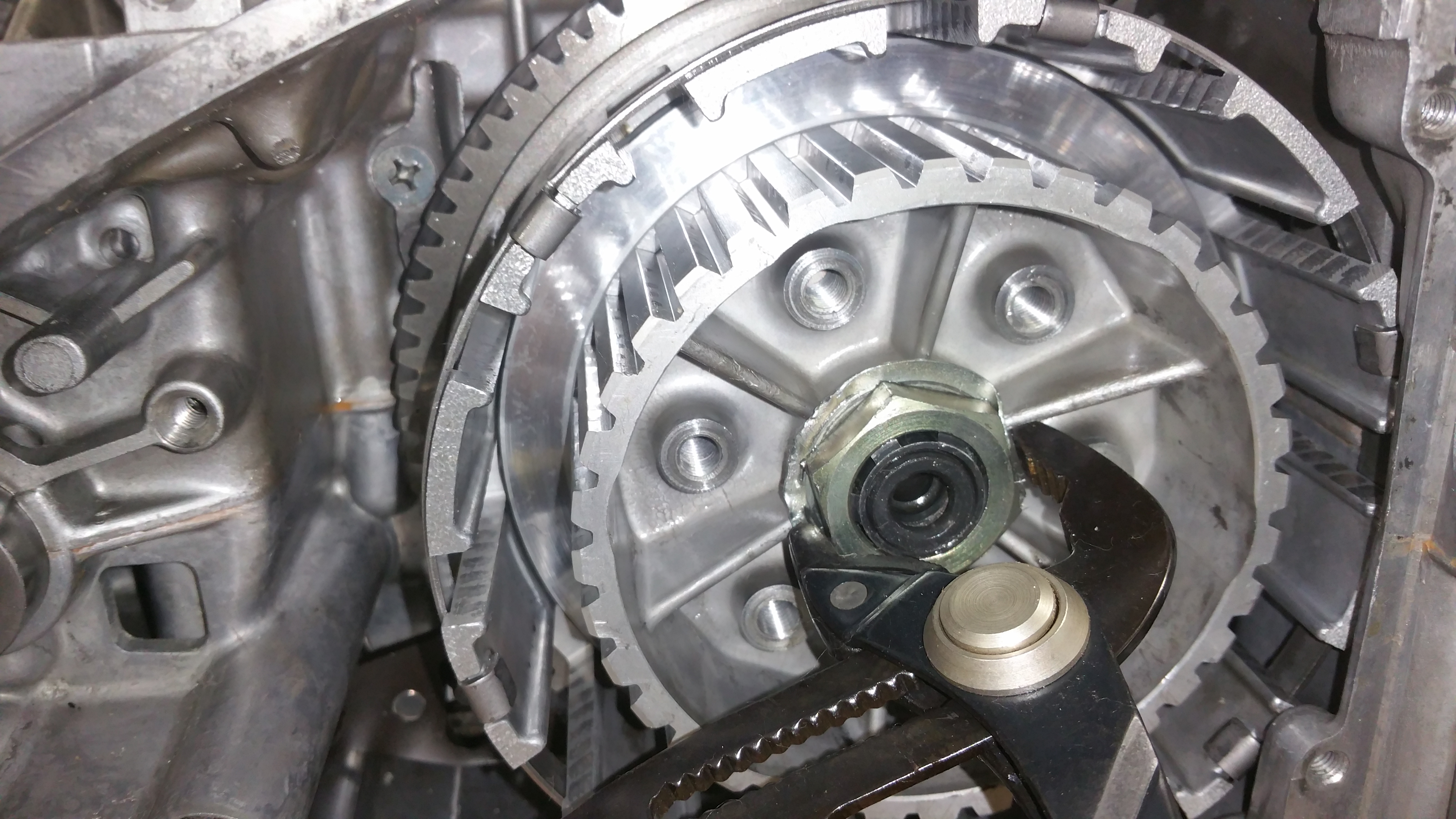
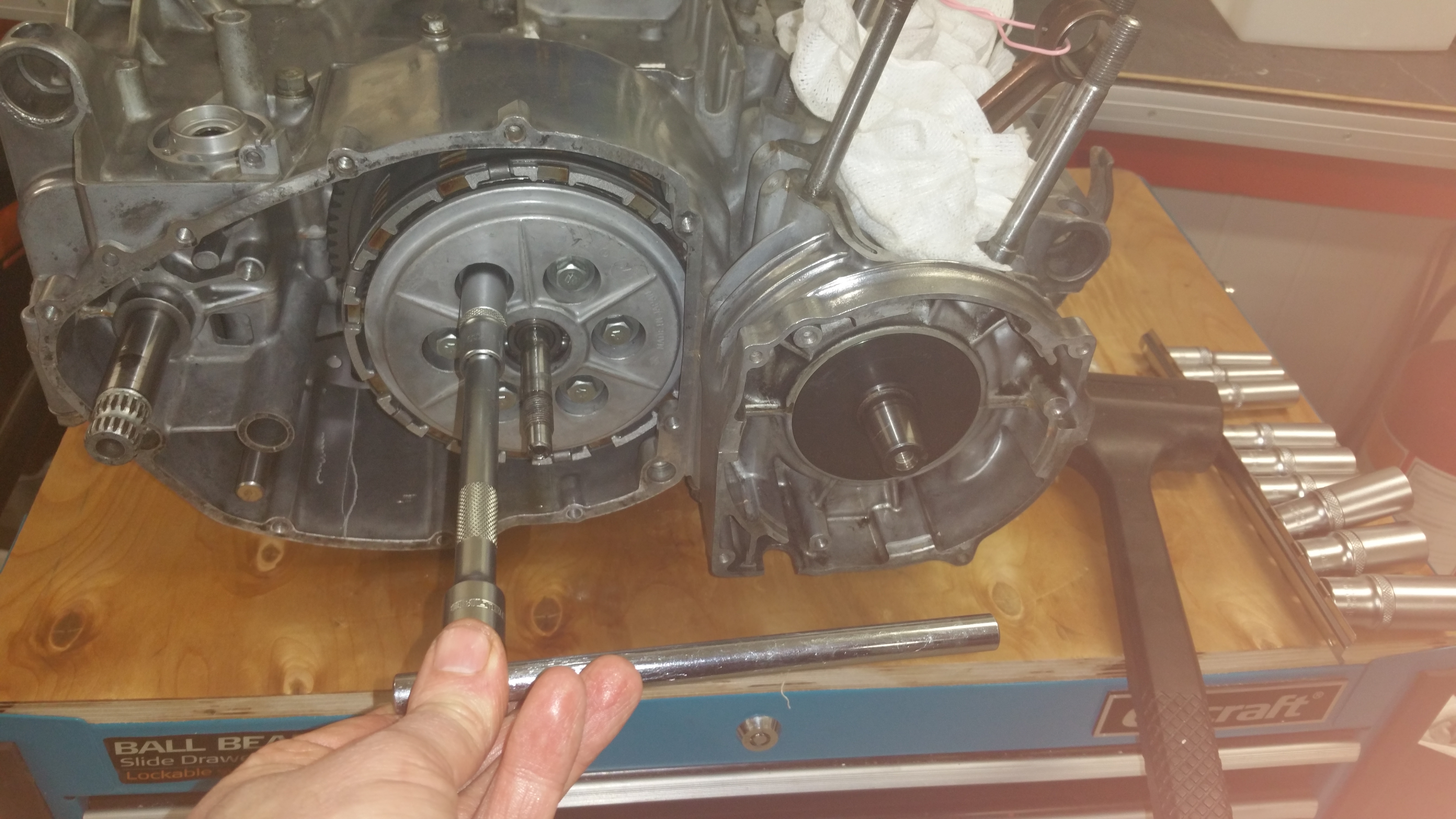
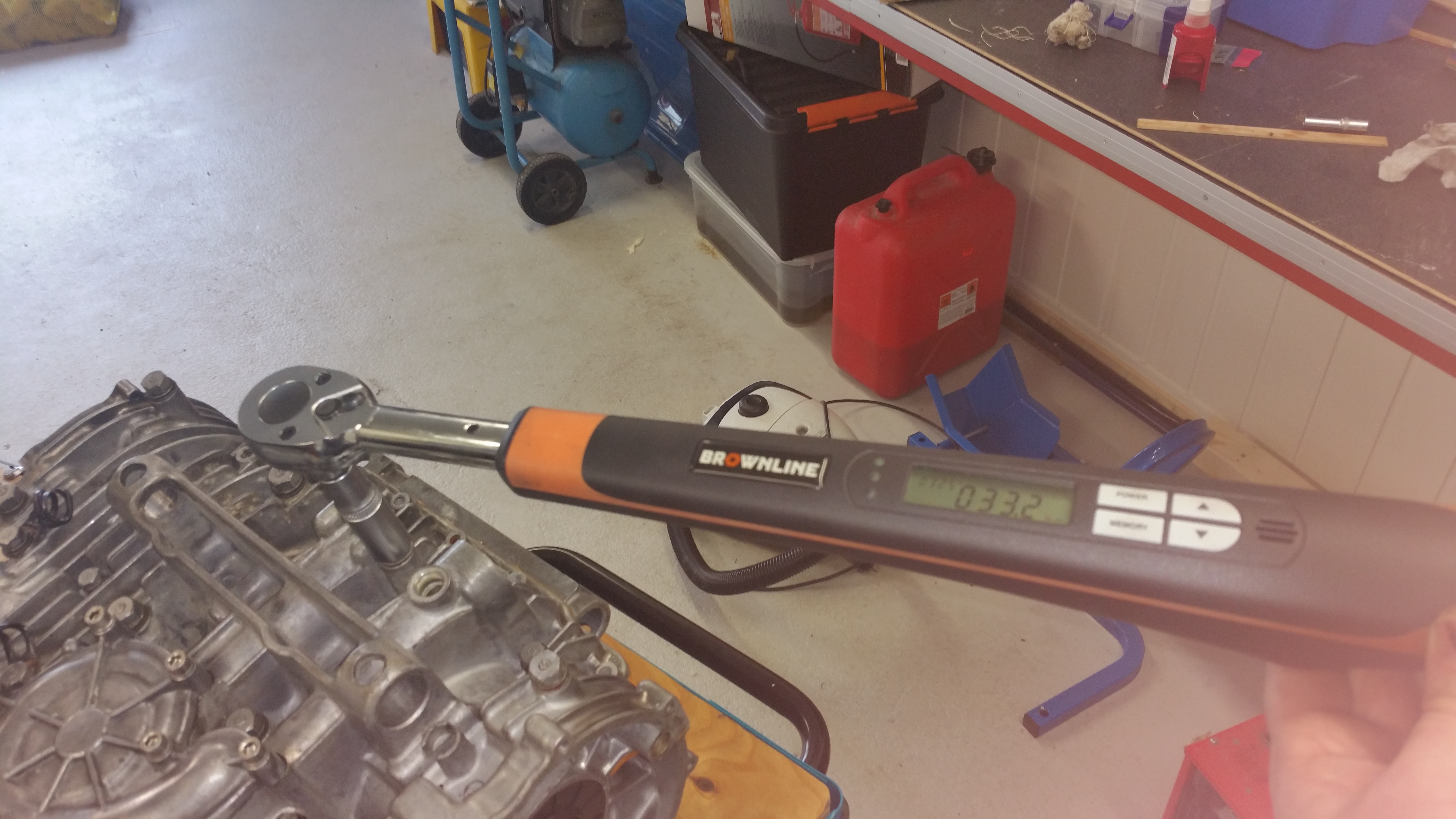
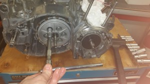
Torque setting for the center nut is about 50 Nm.
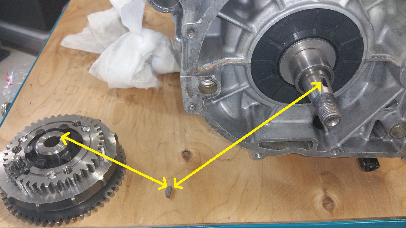
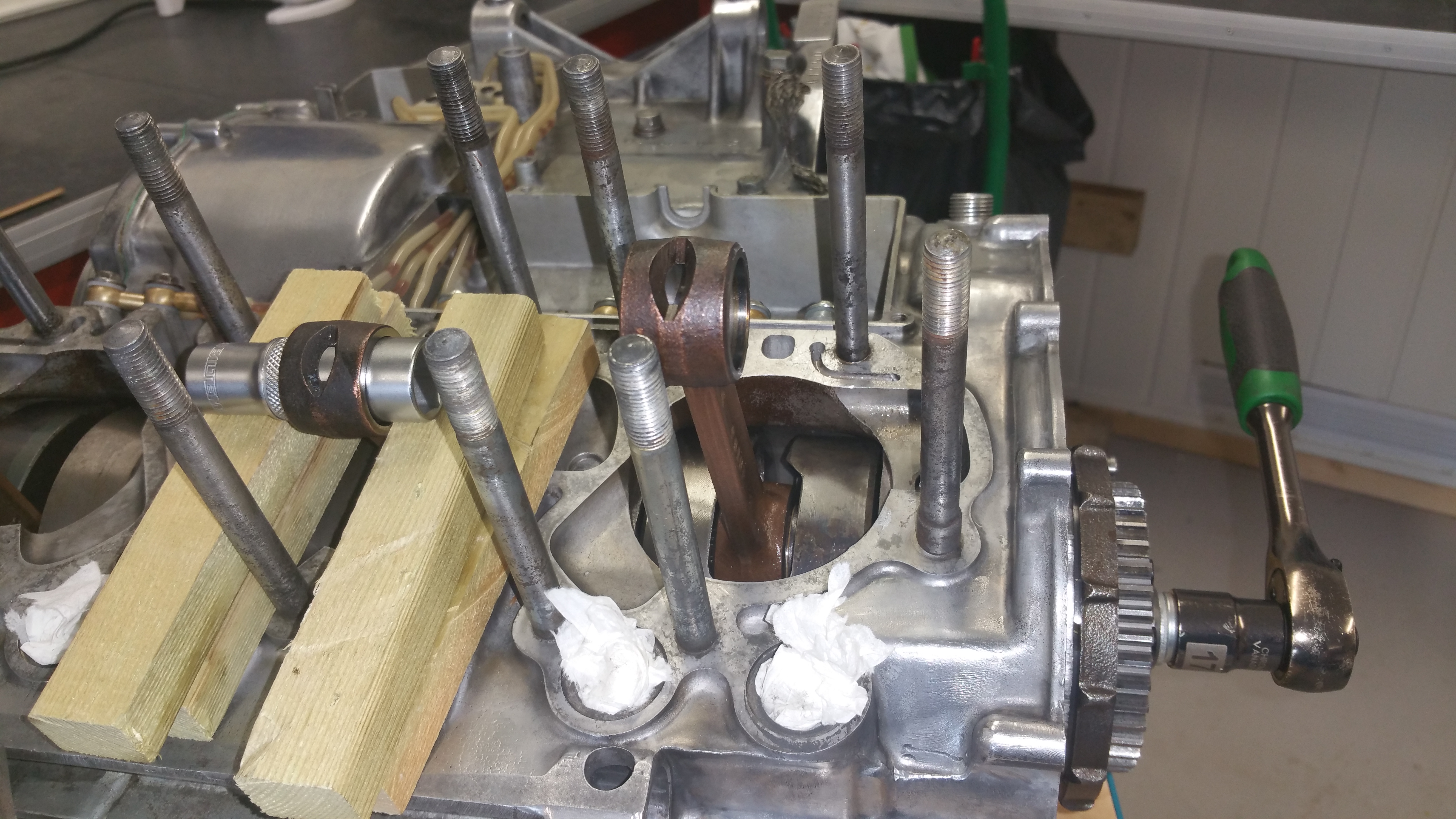
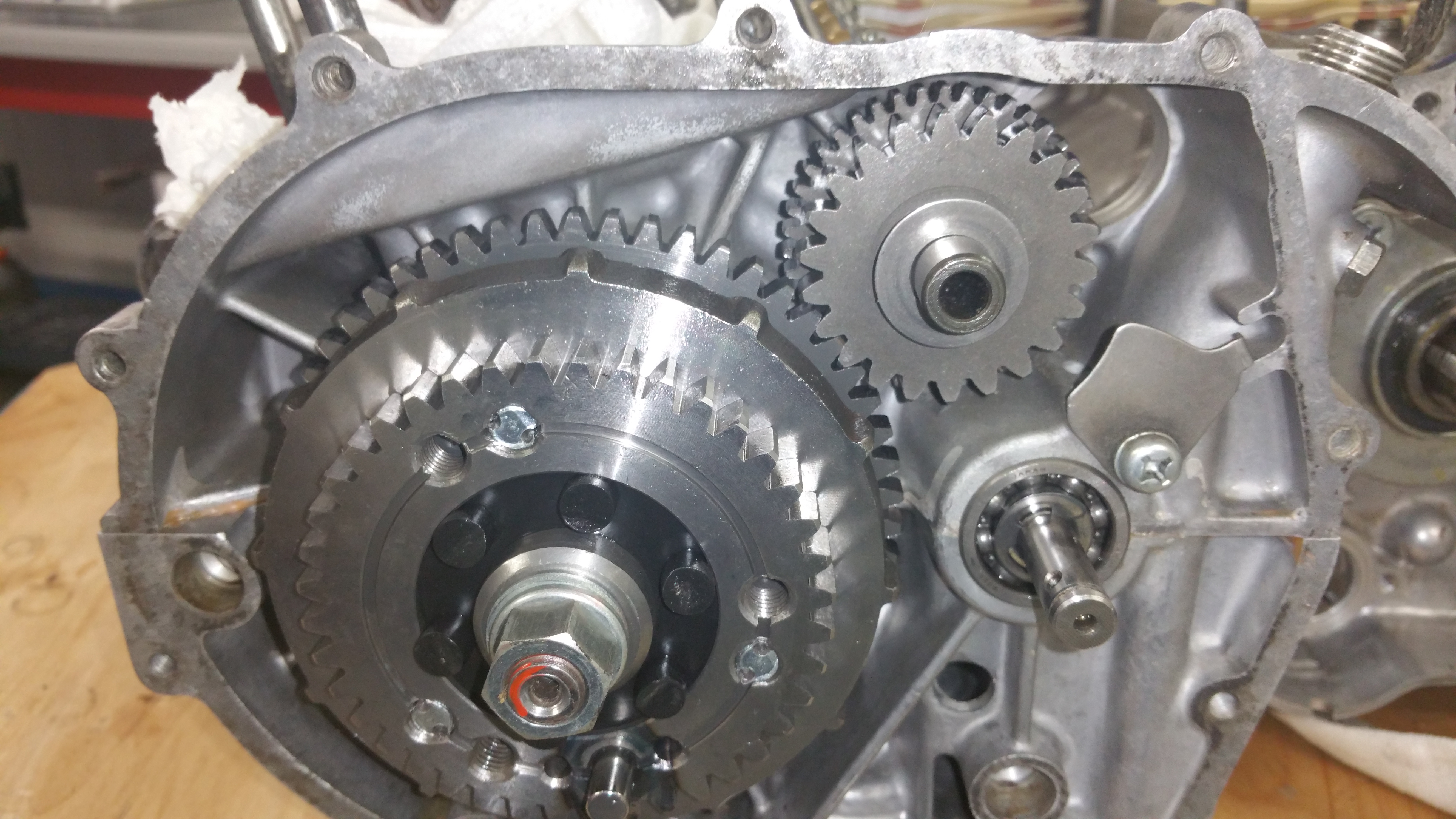
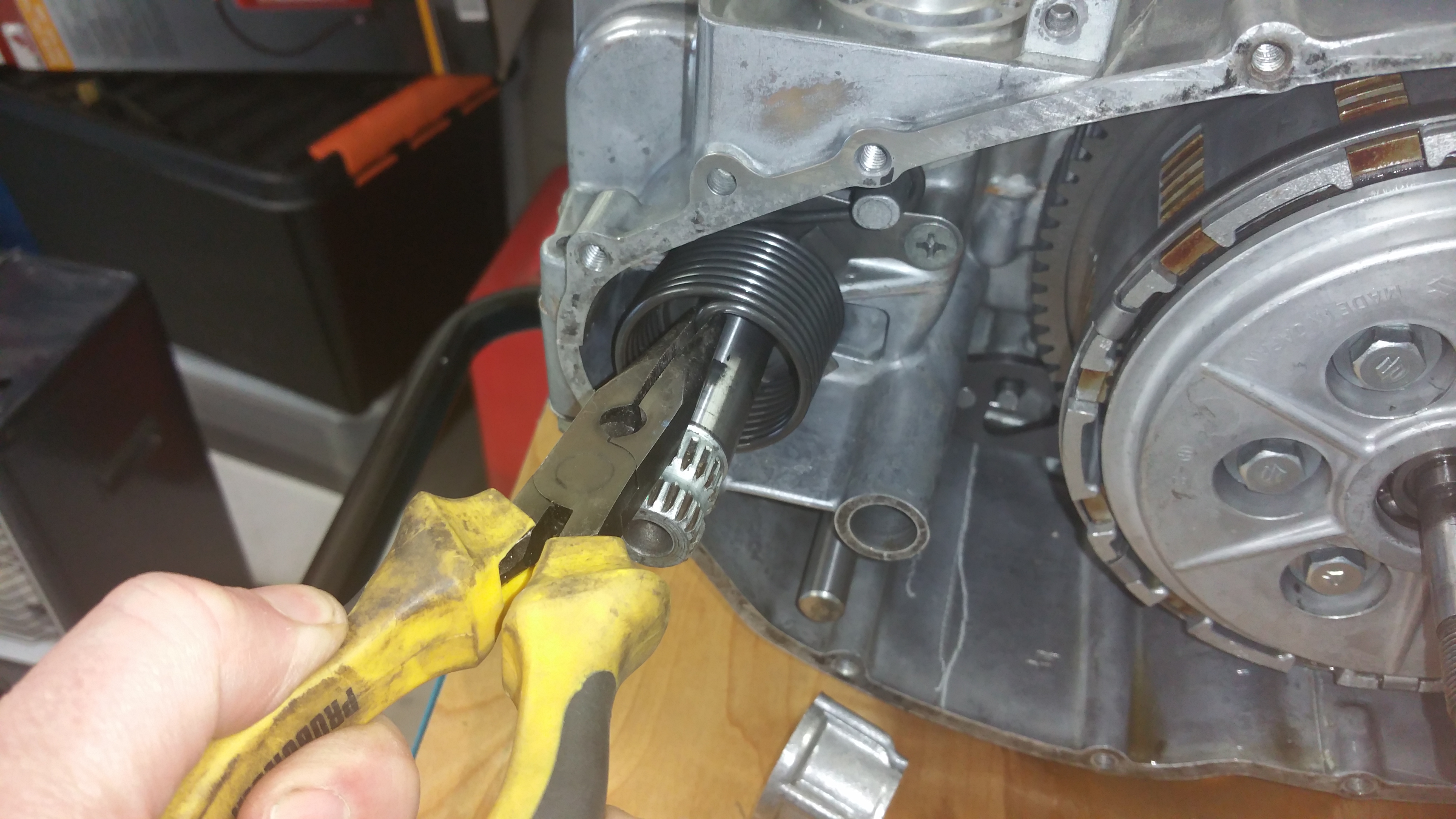
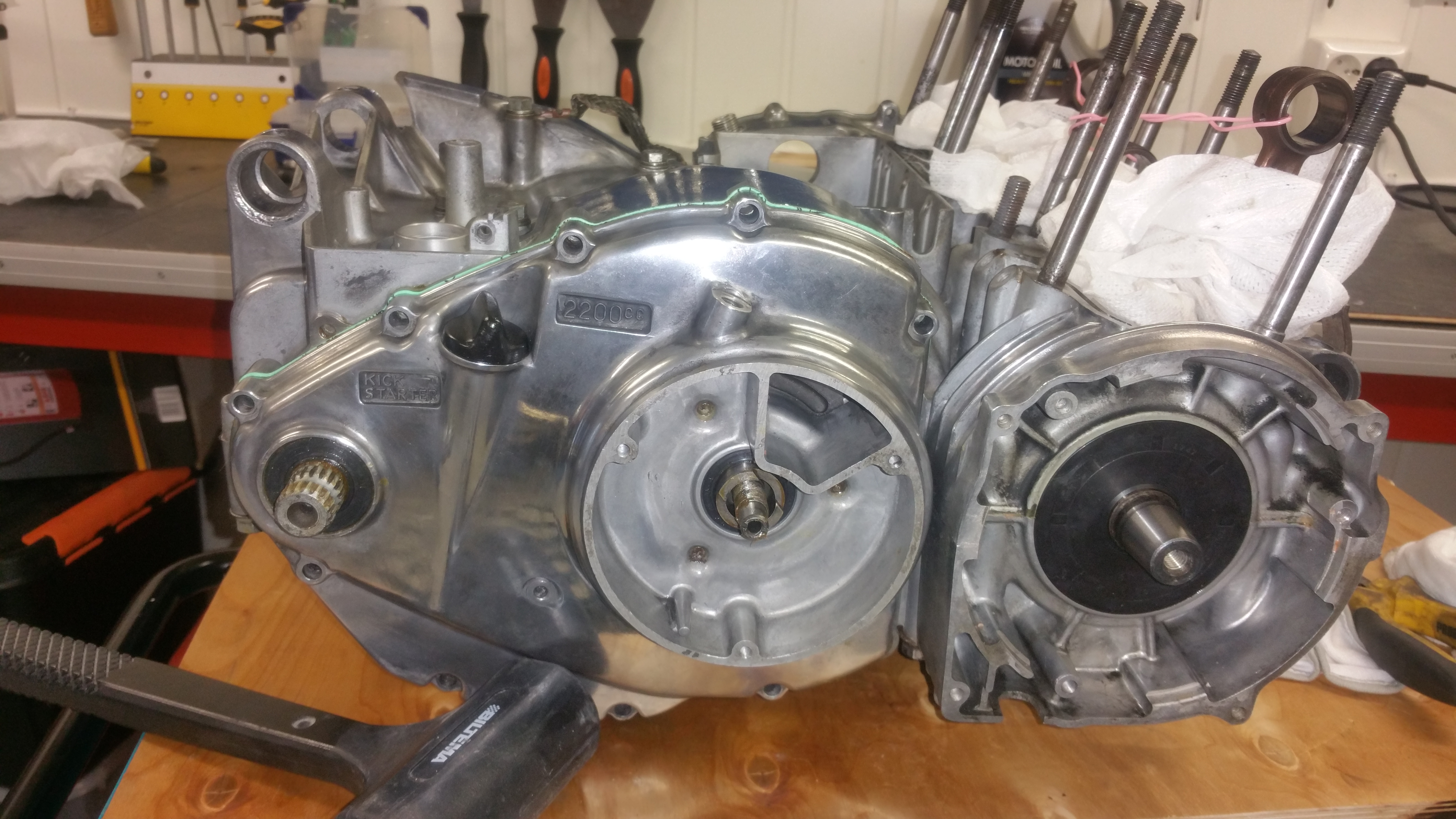
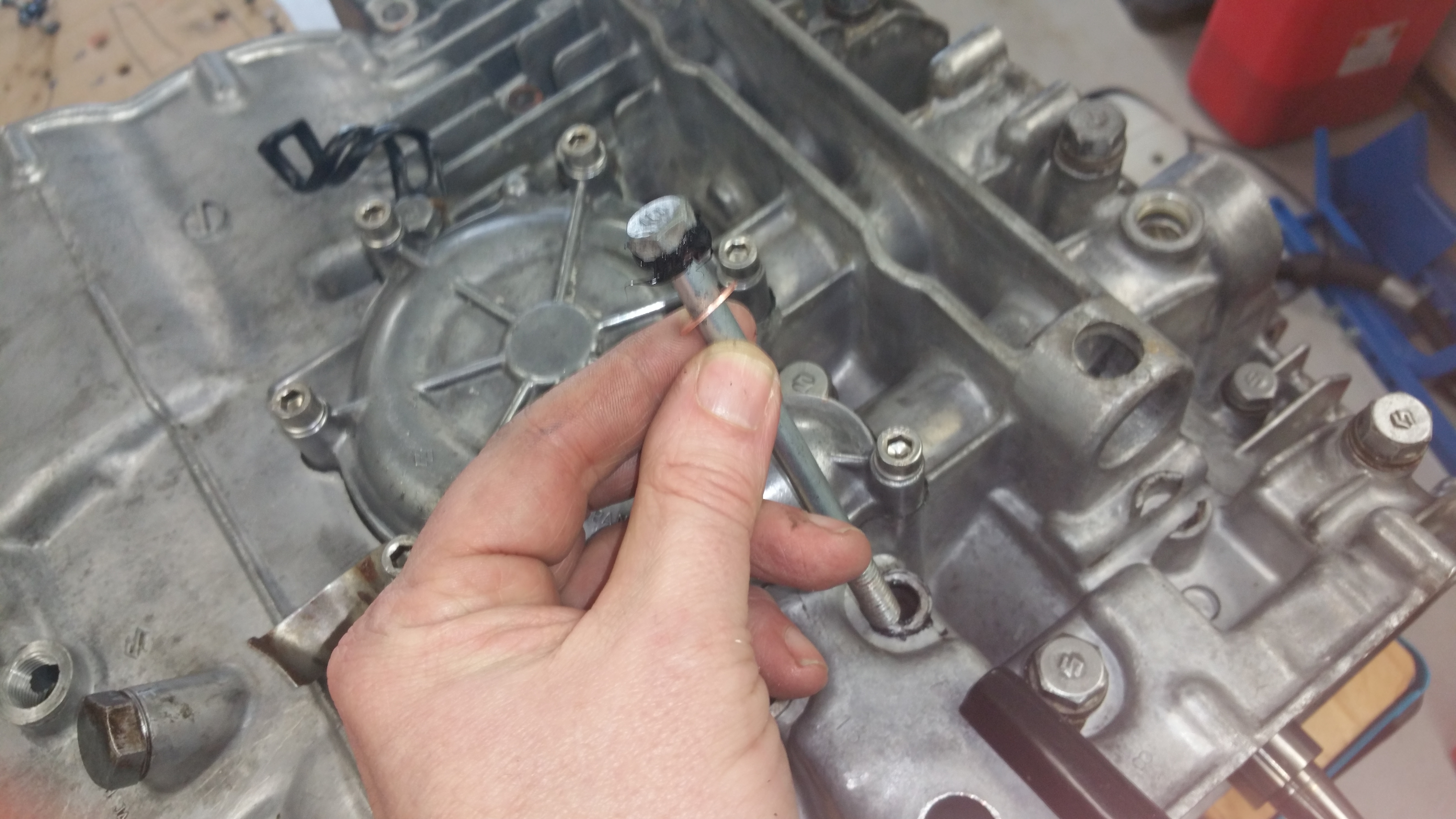
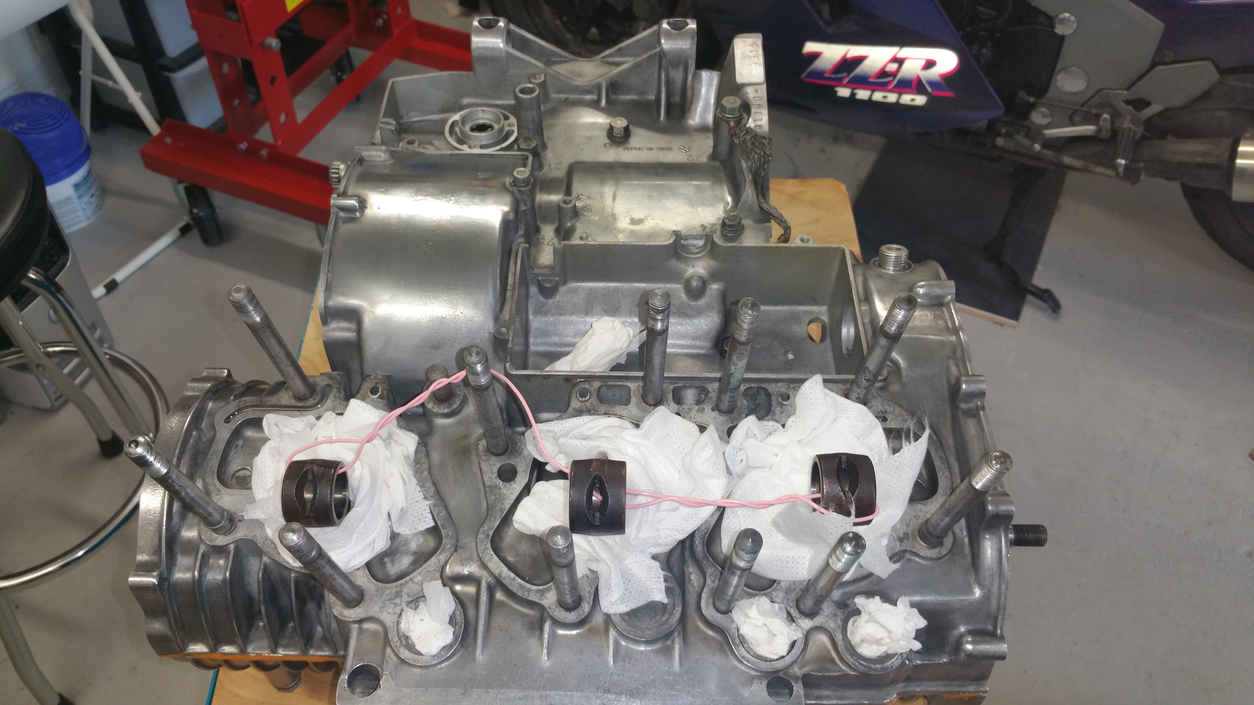
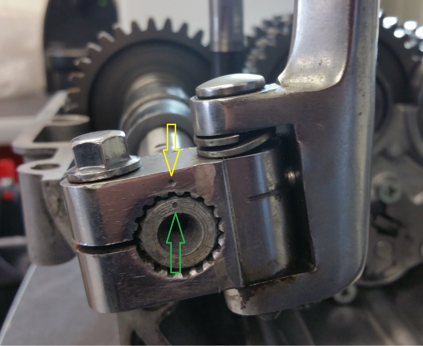
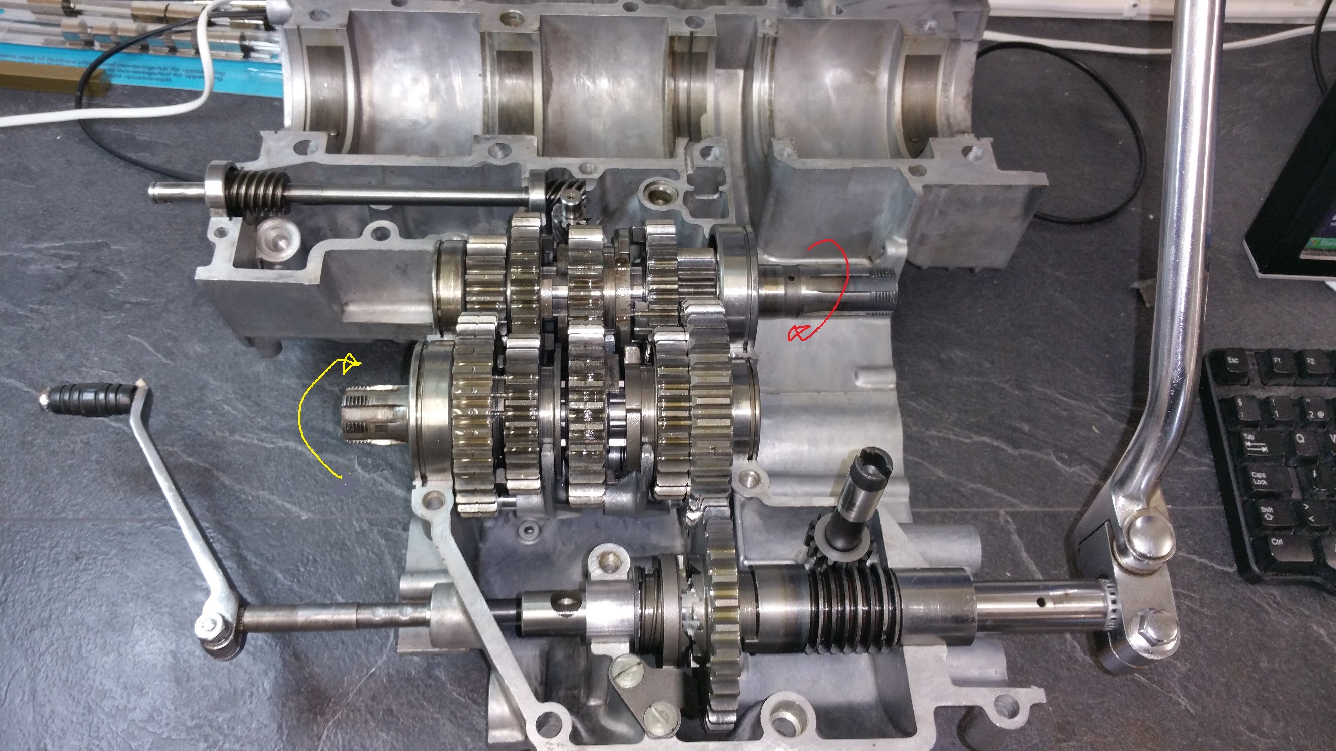
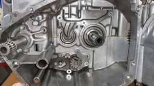
Before torquing up the center nut you need to some how lock the sleeve hub (5) Never use a screwdriver on the edges. You can make a special tool using old steel plates from a clutch. I had no such tool but did it in this way:
Lock into one of the gears and do something clever to lock the front sprocket, like I did on the photo above.
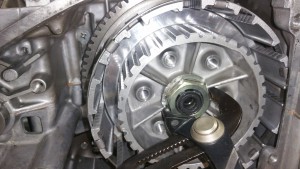
Don’t forget to bend the “new” lock washer. One of the edges is enough.
Step 9:
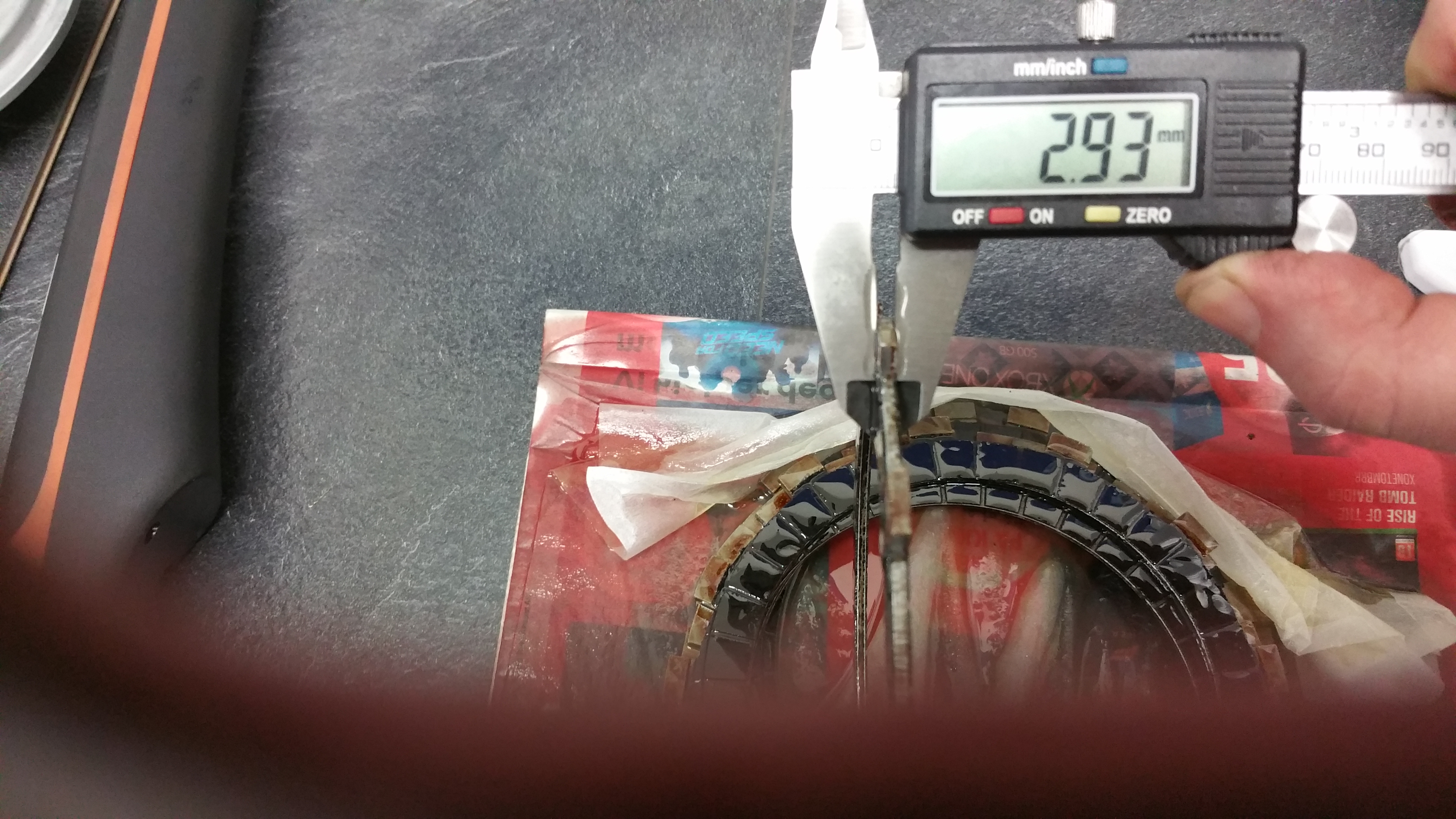
Before mounting the clutch check the specifications of the cork plates and the springs
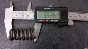
STD lenght: 40,4mm. Spring setting limit :1,4mm

STD thickness: 2,9-3,1mm. Wear limit: 0,2mm
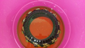
Let the cork plates be quite oily before you mount them
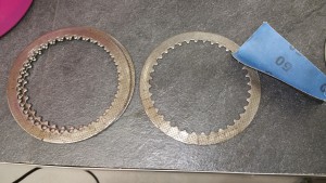
Grind off any layers from the steel plates.
Start with the cork plate, then the steel plate. The last plate should be a cork plate. The steel plate has a little radius on one side and a flat side on the other side. The flat side at the bottom and the radius facing against the front.
8 cork plates and 7 steel plates.
And as you can see, I found the new lock washer after I had completed the assembly.
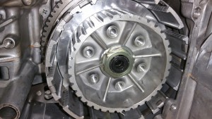
Step 10:
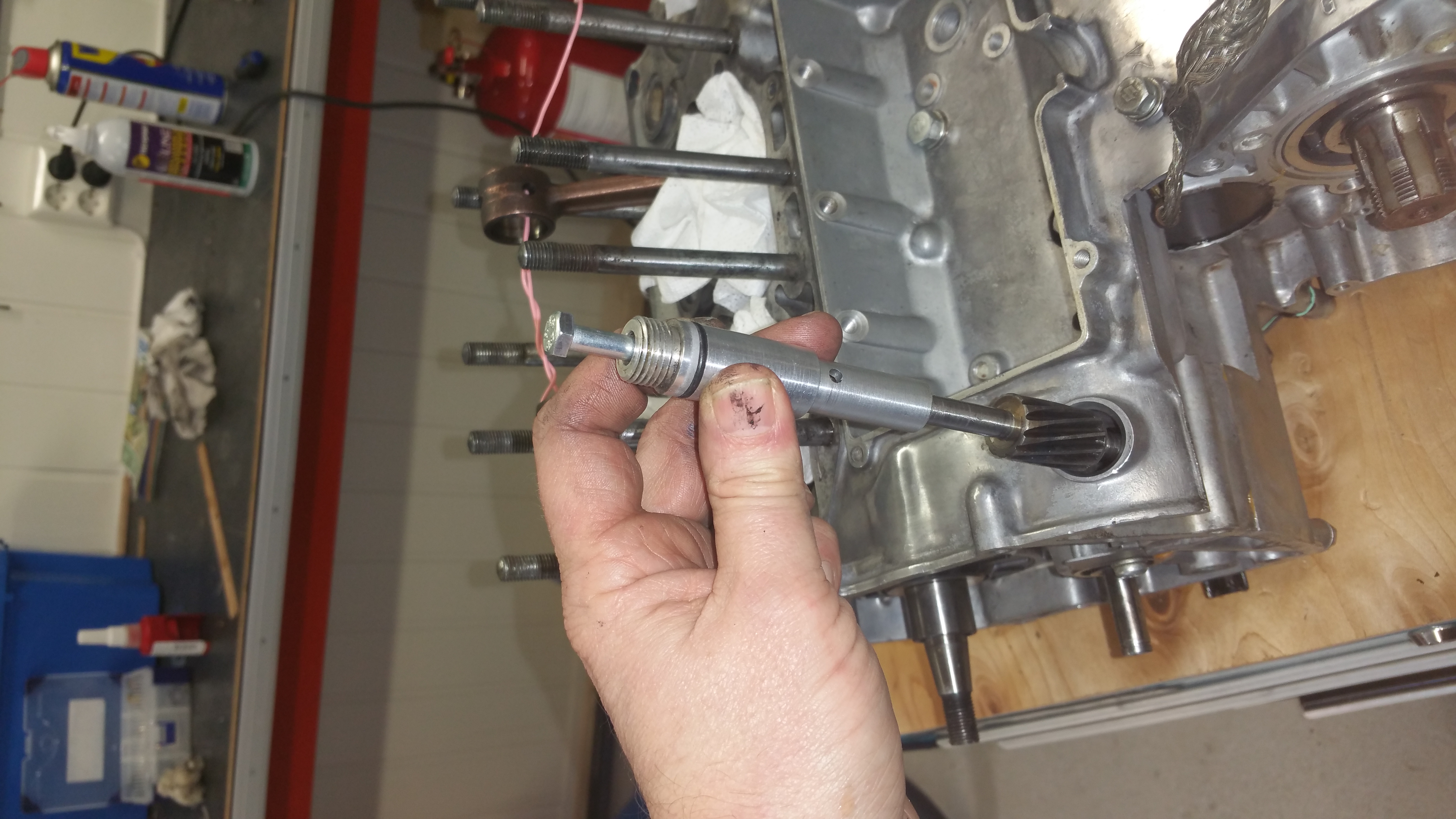
Mounting the clutch pressure disk.

Remeber the mount the clutch release shaft (17)
Mount the bolts in a pattern for an even distribution of the force. When all bolts are driven home you just give it a tap . No torque settings
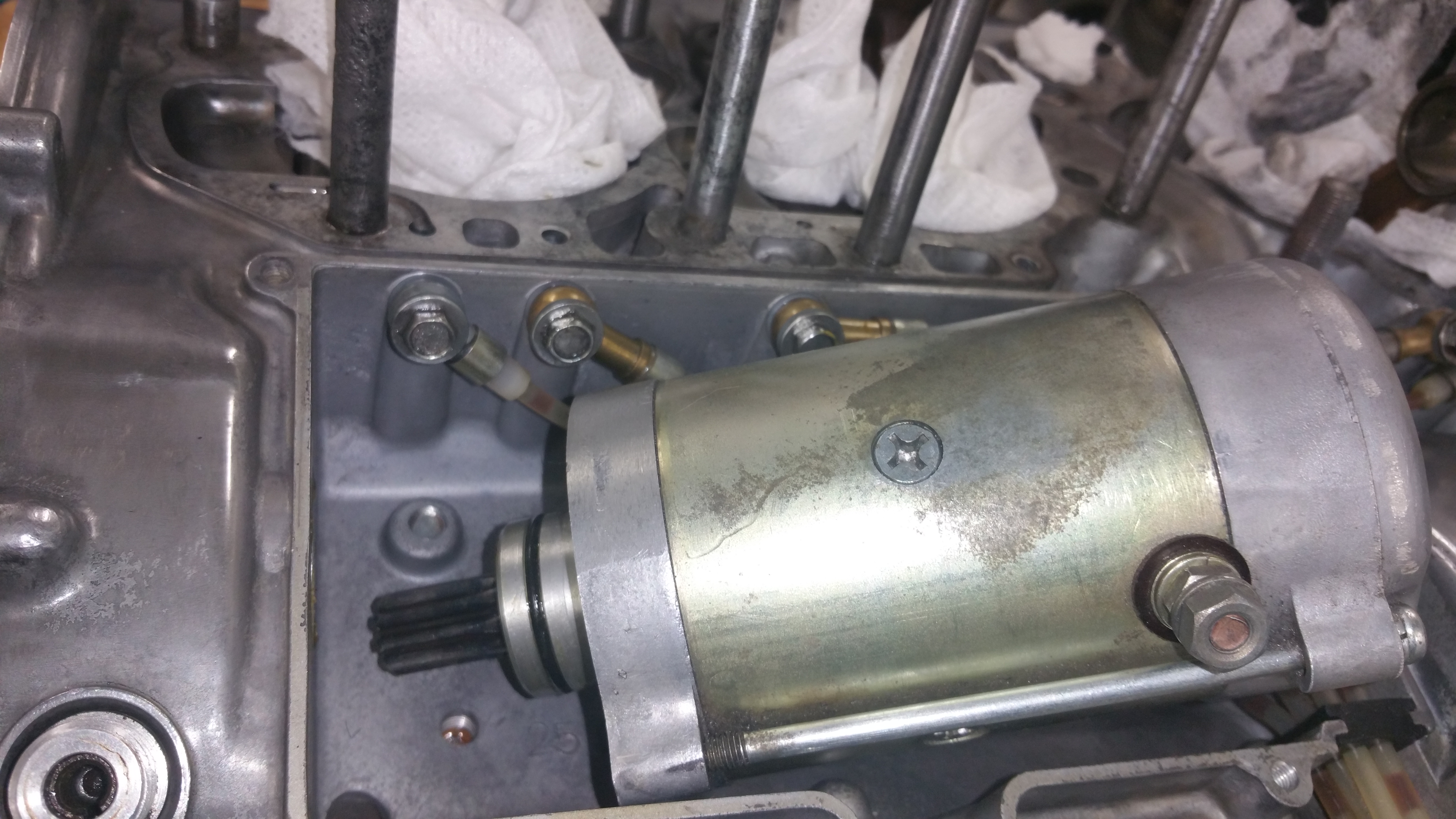
Step 11
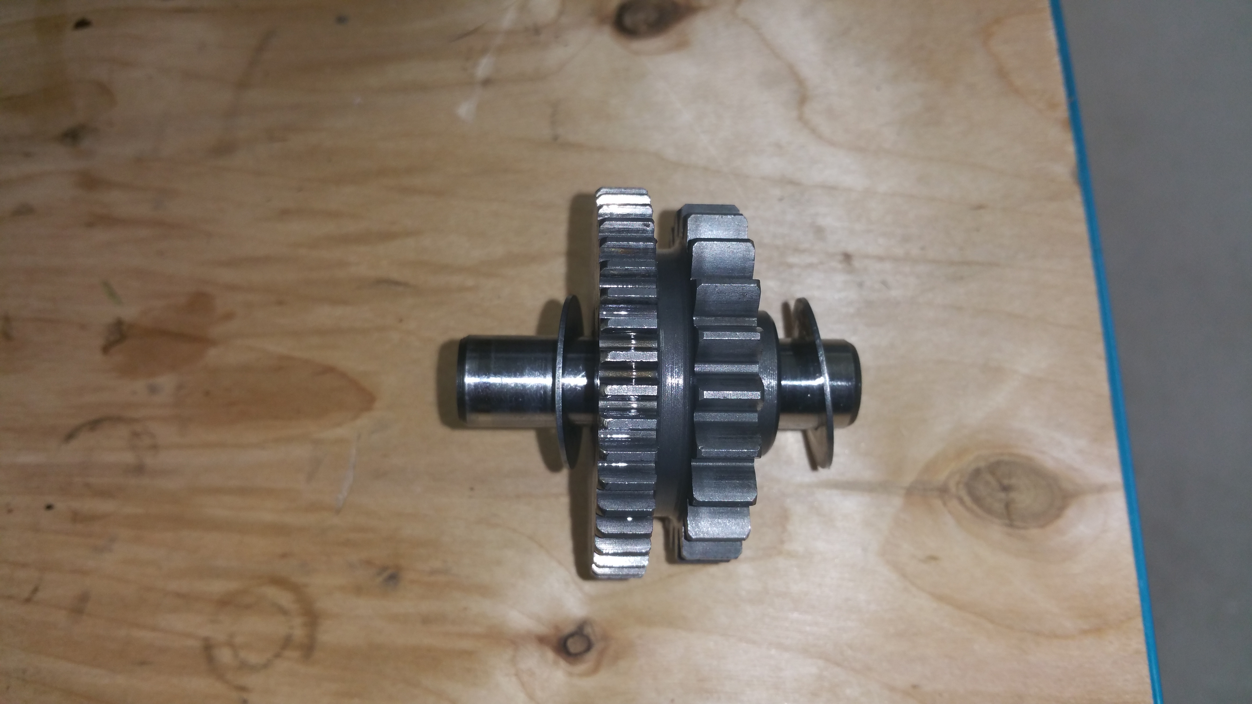
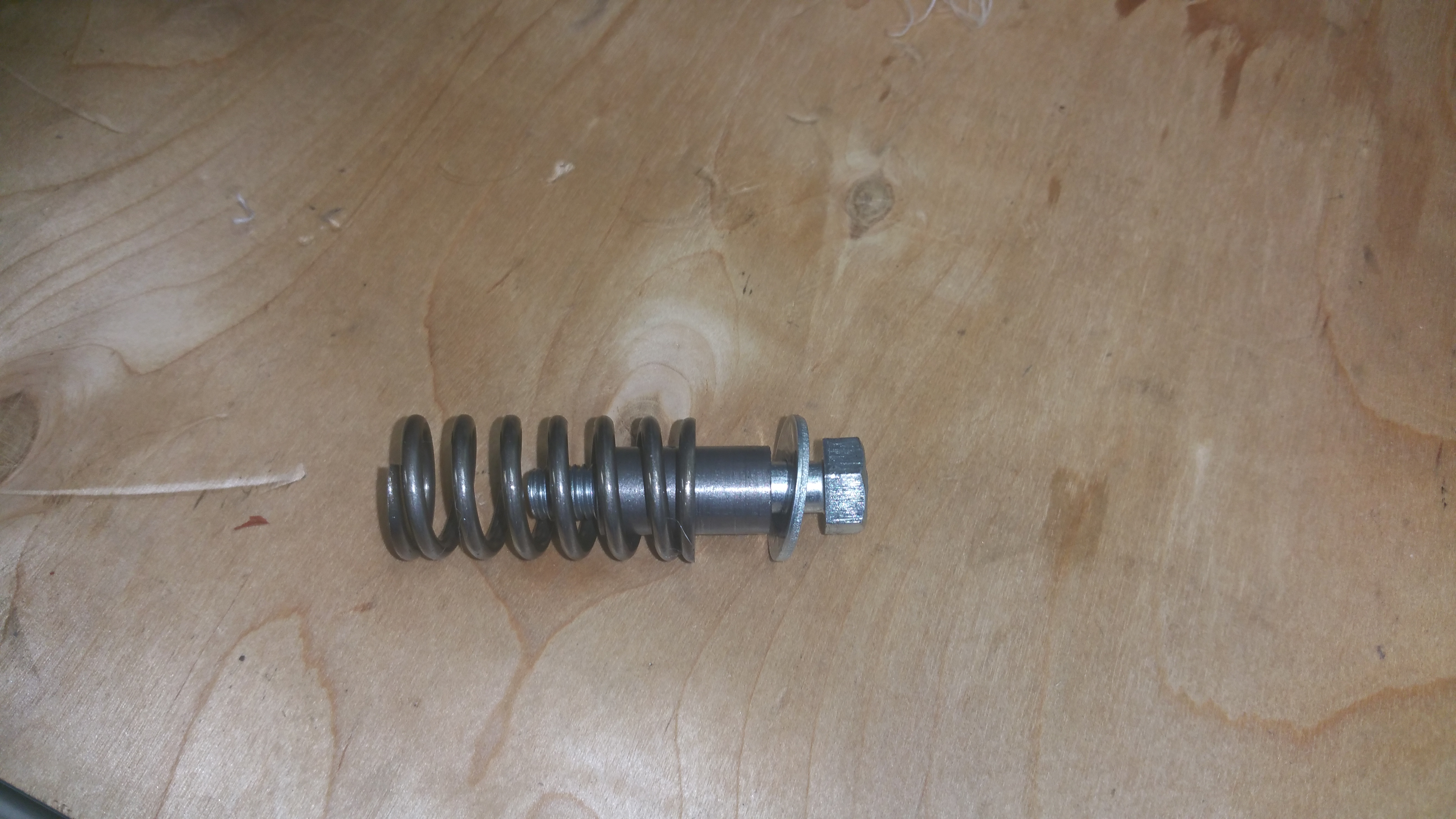
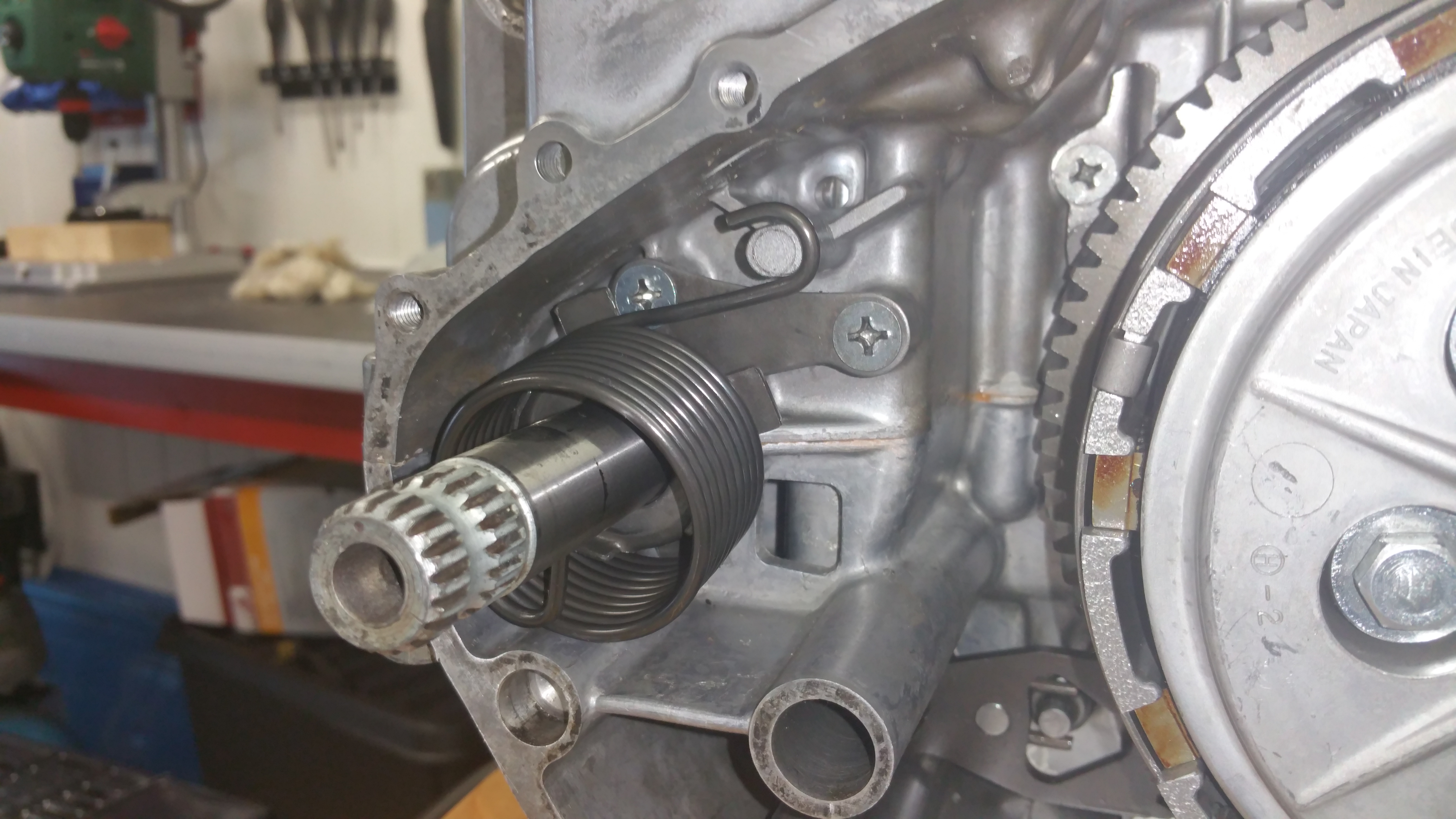
Kick starter

Mount the spring holder (and the plate behind if not already mounted)

Mount the spring

Competed !
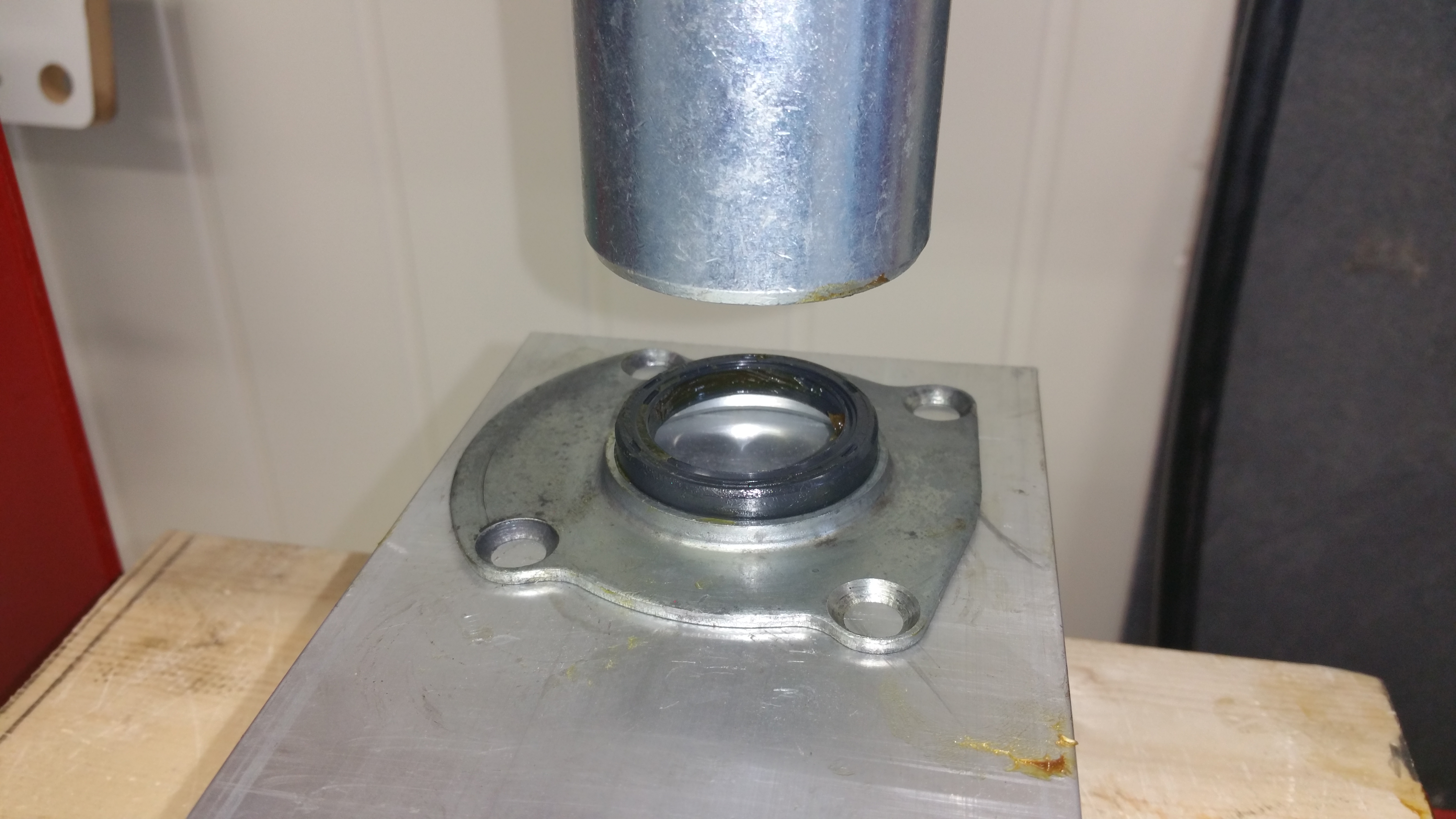
Step 12
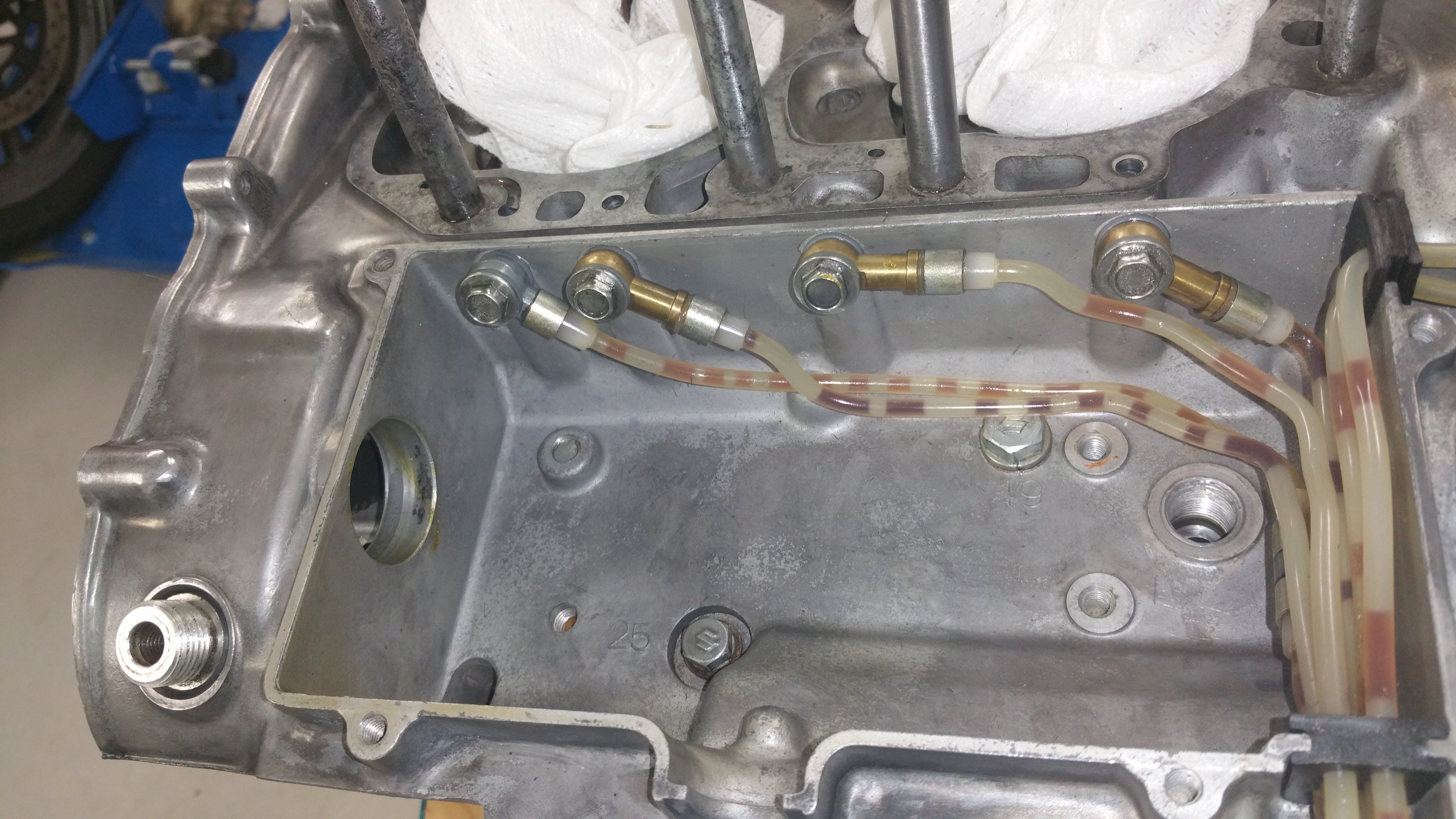
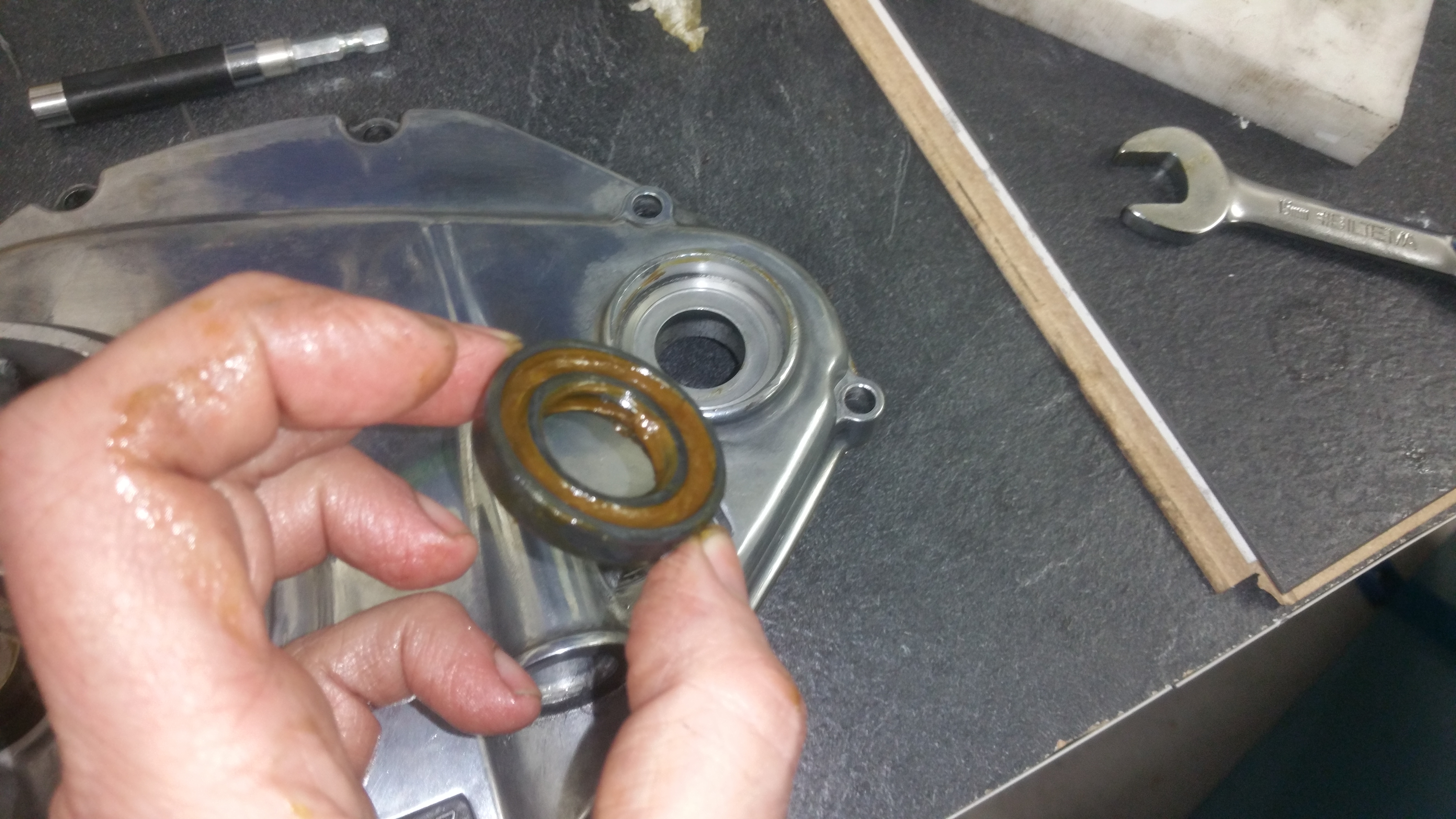
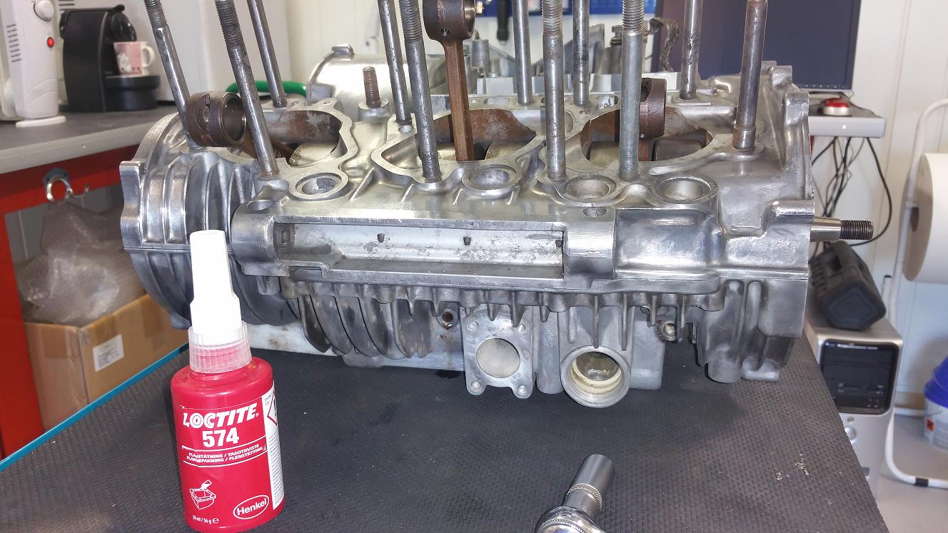
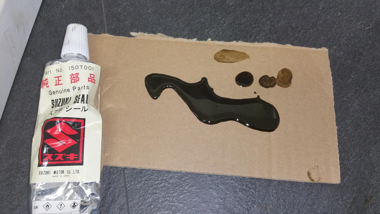
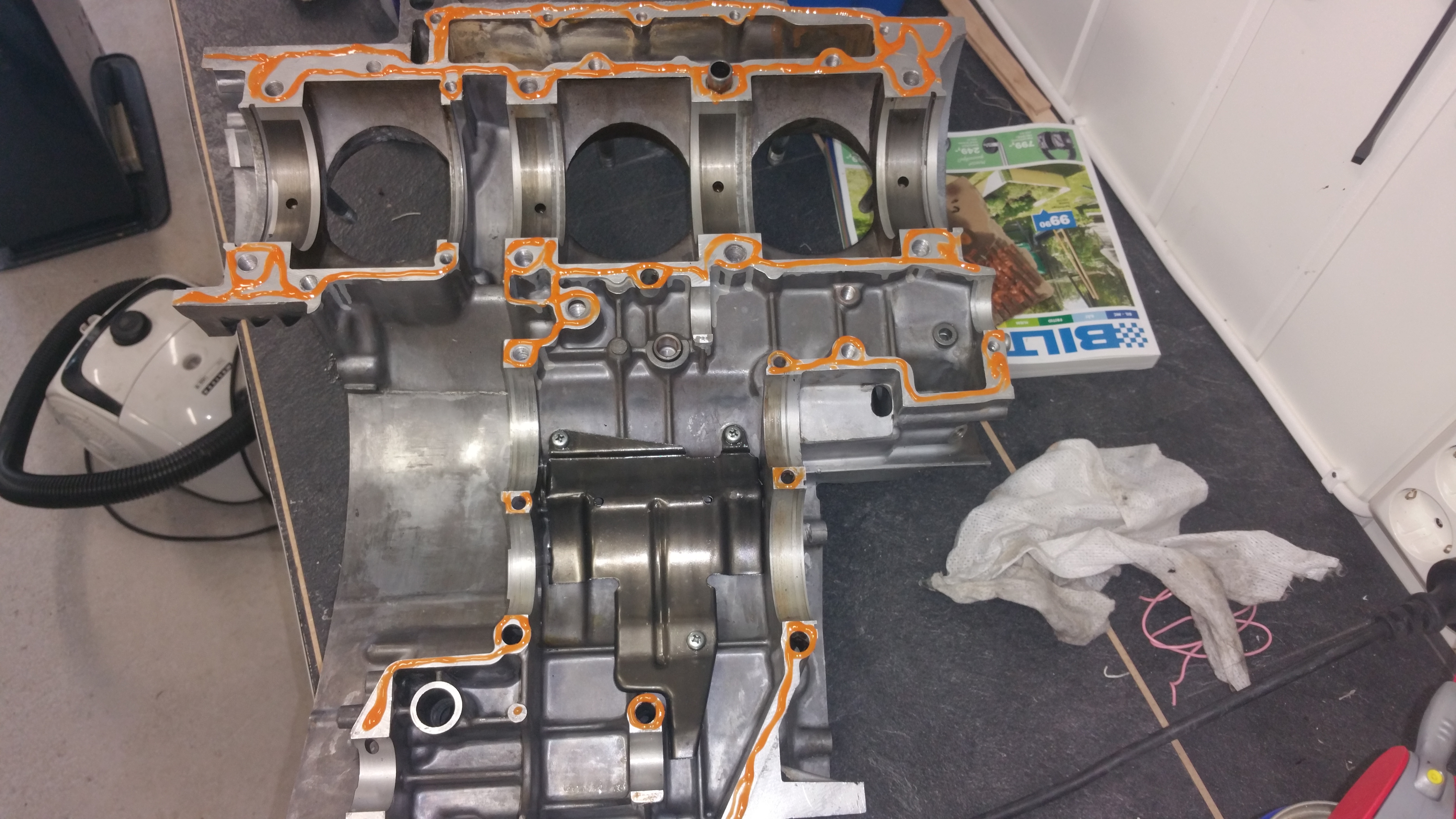
Mounting oil seals, gasket and side cover
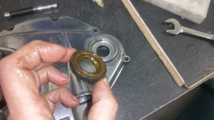
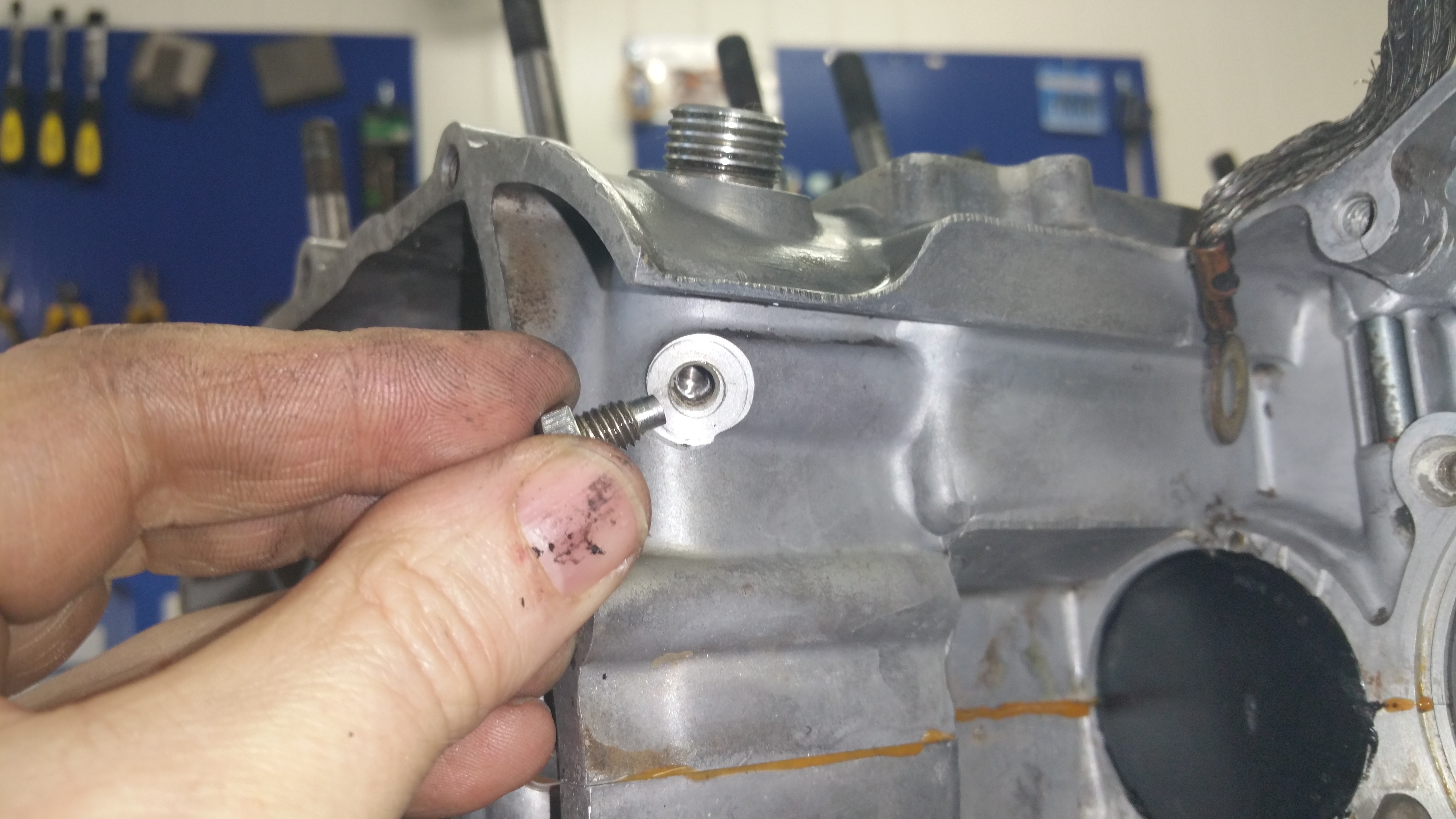
There are two oil seals in the cover, both should / can ( depends on age) be replaced. Add grease on the seal side.
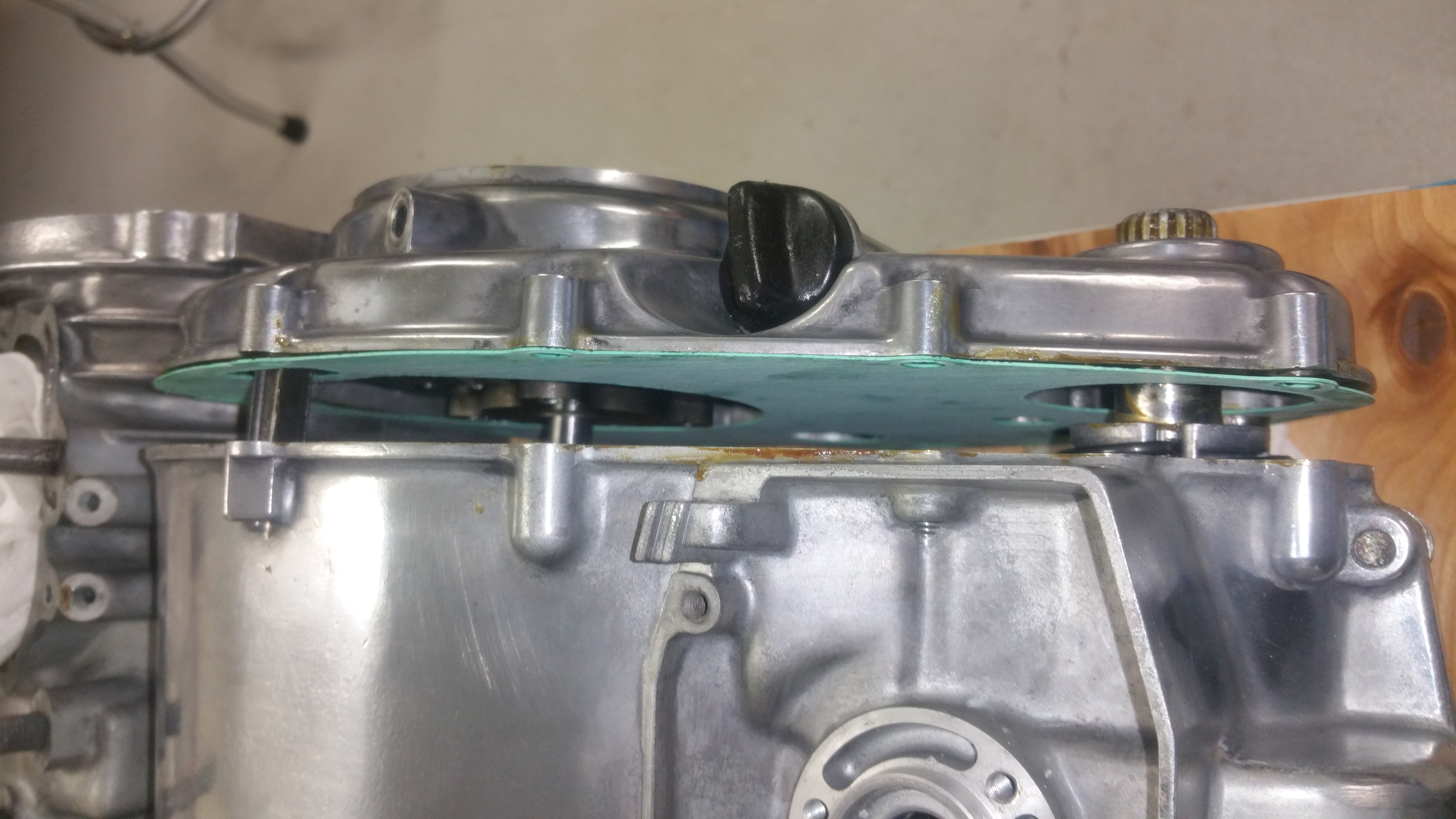
I found both mounting studs quite stuck in the cover, not at the case side. Therefore I put the gasket at the cover side.


Done !