Browse Category: Suzuki GT 380

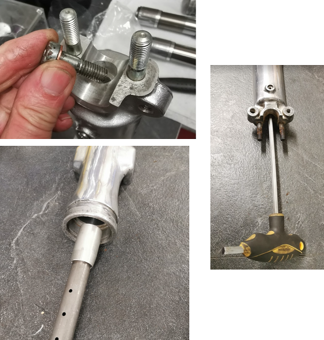
Assembly of the front fork

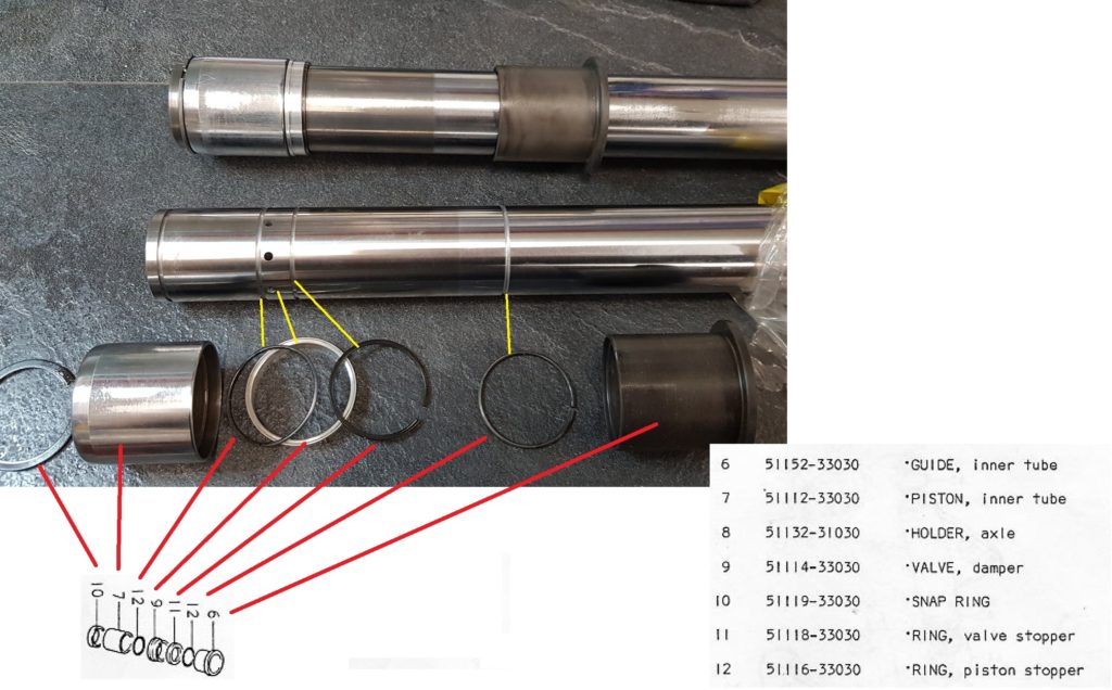
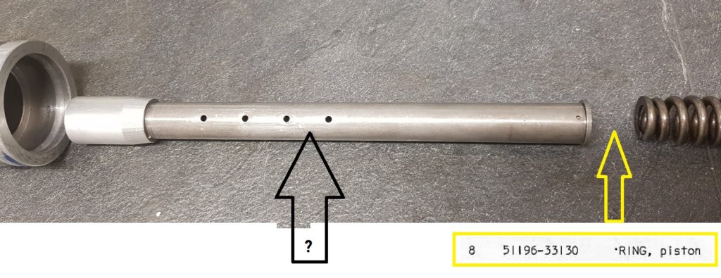
Mount the damping rod (unknown part no) into the outer tube. Don’t forget the copper washer.
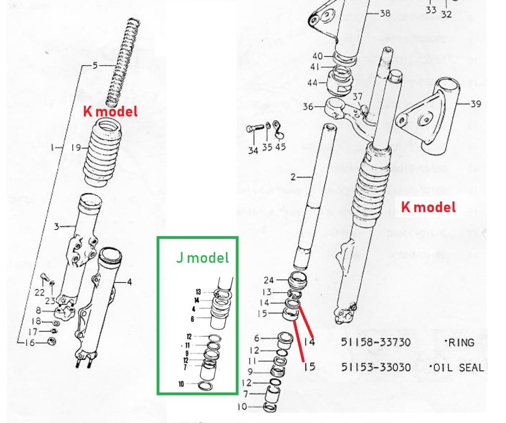
Oil seal:

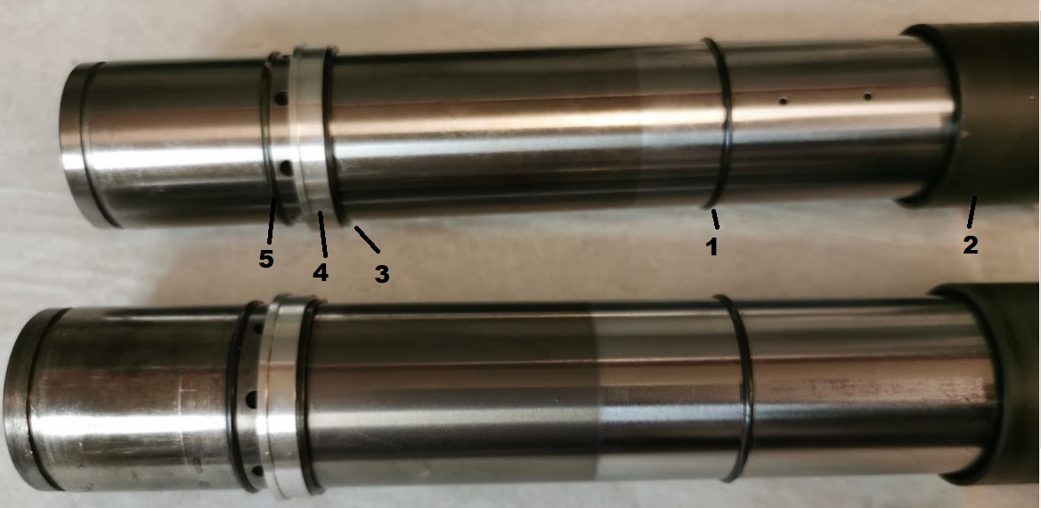
Mount the inner tube and slide the oil seal down to the outer tube.

Next step can be difficult. Apply som grease around the seal, but it can be hard to drive the oil seal all the way down to the bottom. I did it “my way”

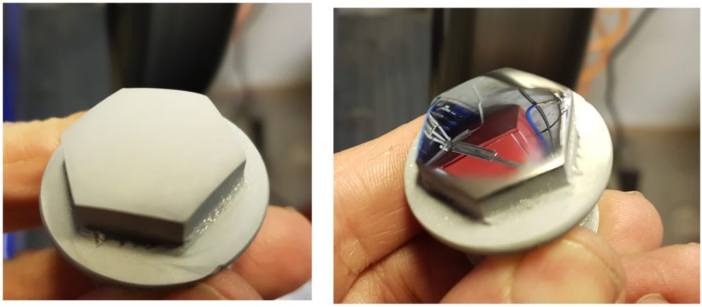
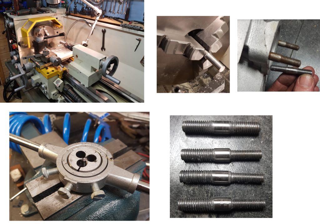
Since I have a lathe, I made a tool for the purpose.

With a plastic tube on top of the tool and a hammer it was easy to drive the seal all the way down.

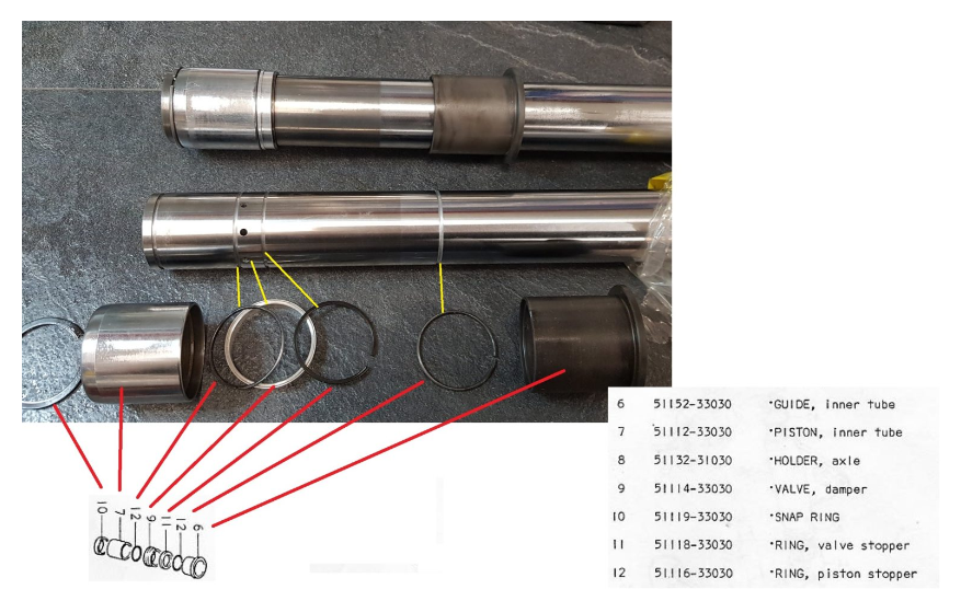
Secure the oil seal with the circlip and the spacer.

Fork oil:

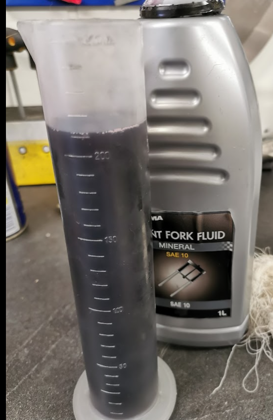
Install the fork spring and apply 210ml of oil. Screw on the top bolt and you are done 🙂

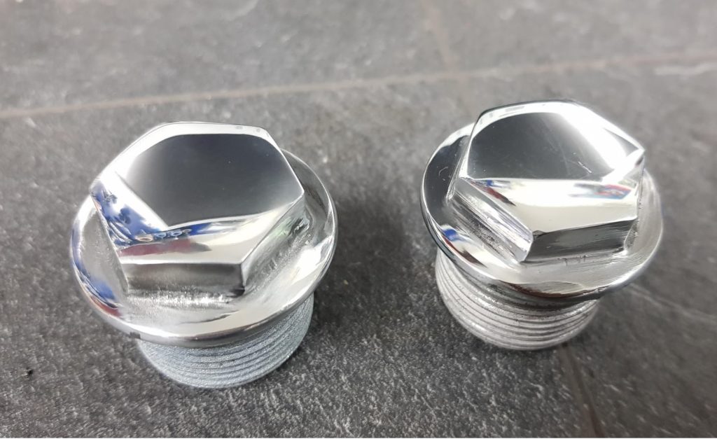
Don’ forget the drain screw at the bottom.

Mounting the fork boot:

This part turned out to be very difficult. The lower end of the boot was very stiff and not flexible at all, and looked too narrow to get around the outer tube.

Soften the boot with hot air helped, and by using some plastic stripes as a guid I was able to squeeze it on.

Inner tubes

Finally, after two years of nothing I’m back on track with the restoration process.

Luckily I did some research last time about what part to be fitted in the correct order.

I used images from my previous post about the topic and went a head and did the assembling of the inner tubes.

7 Steps:

Fork top bolt

What to do with the top bolt of the fork leg ?

Step 1: Sand blasting as shown on the picuture above.

Step 2: Grind and get rid of all remains from the old chrome.

Step 3: Use fine grit size on the sandpaper to obtain a shiny surface.

Step 4: Start electro nickel plating. As shown previous on my blog I use the same old bath with the same solvent I made 7-8 years ago. The nickel anode is the only part that needs to be replaced after some time.

After few hours (4-8 hours total electrolyze time) the bolt will be covered with nickel. The gray surface needs to be polished to get shiny.

Done :

Clutch and timing cover

Polishing the engine cover on the right side:

Phuu, a lot of work, dirty work as well. Dust all over my face.

I have three engine covers to choose from. Two of them have some very bad scratches, too bad to ever look good again. Got hold of an unused one, the new type with 1500cc oil level label.

The bad ones:

Parts for the timing will be removed and reused in the new cover. One of them has a very good nylon gear for the timing assembly.

Timing cover:

Before and after one hour of grinding and polishing. Had to grind off a lot of material to remove some deep dents and scratches. Still some scratches left but the cover will be replaced later on with a J cover with engraved Suzuki logo. This is a later model with a sticker in the middle.

Cylinders

Got a surprise when starting to assemble the cylinders. Some of the 8mm stud bolts where missing and had been replaced with 6mm bolts.

This is what happens when working on a 48 years old project. Previous owners must have been too careless while mounting the pipes, as usually, too much torque and the threads are gone. A bit odd fix. They have used 6mm insterts in three places. I can’t have a mix of 8mm stud bolts and 6mm bolts. Not on a bike as stunning as this 🙂 So, what to do ?

Having a lathe is a big advantage while doing overhaul on a bike, a worn out bike.

Made four new studs. One original with 8mm threads in both ends and three with 8 and 6mm. One of the 6mm came out a bit bent, will fix it.

Done ! 🙂

Threads :

I did a refresh of the threads on both the bolts and the nuts. Not to get a surprise during the mounting.

10mmx1,25mm fine pitch threads.

Piston rings:

Before mounting the cylinder, make sure the gap in the piston ring is above the pin located in the groove.

Mounting of the cylinders:

Mount the gaskets and start with the cylinder in the middle. Apply some 2-stroke oil and slide the cylinder down. Don’t forget about the position of the piston ring to close above the little pin. Should slide easy down, not needed to use any force.

The last one and it’s done.

I was not able to find any torque settings for the cylindres, only for the cylinder head. Since there is no space to use torque wrench on the nuts I used the tools I had and fasten using sensible amount of torque 🙂

SRIS:

All of the cylinders have plugged SRIS outlets. I will therefore mount the case without the SRIS valve no.17. Dont’ see any issues of burning a bit more smoke at startup.

Pistons

Time to assemble the pistons. Bought a kit with piston, circlip, bearing and the pin.

The procedure is wery much the same as shown in my GT750 post some years ago:

GT750 post:

Please we aware of some differences: For the GT 380 all three pistons are identical. There are no washer in the piston as on the latest GT750 models, only the circlip to keep the pin in position.

Pictures from the GT380:

Remember to move the circlip gap at the opposite position to the groove, picture 3-4.

Insert the last circlip and you are done (picture 6 )

Done 🙂

Fork headache

Almost a year after last time I looked into this I’m still a bit confused. Difficult to figure out, but I think I’m on the right track now.

Not easy to find parts manual for the J-model. Manuals claiming to do so always starts with the drawings from the K-model. And if I find drawings from the early J version, they are without any part no.

After a lot of research I think I got it. Look at the green box for the J model. No 4 and 14 are both oil seals. For the K-model no 15 is the oil seal and 14 is a ring above the oil seal to lock the seal in position before the no 13 clip.

And why is no 24 part of the drawing, don’t see the need for a dust seal, or if it can be fitted underneath the no.19 boot ?

Anyhow, I will order parts according to the K-model since it’s an upgrade from the J. All other parts seems to be the same.

Next headache:

Can’t use the photos I took while dismounting the fork. It’s a mess from previous owners. No 9, the valve damper was mounted upside down. No 11 and 12 had swapped placements. The order of the parts at the picture above shuld now be correct.

Was lucky to get hold of a brand new outer tube and a new inner tube. In addition I bought a used inner tube in a good condition. I can therefore replace both of the old inner tubes.

Final headache:

The tube at the picture above, screwed down into the bottom of the outer tube can’t be seen on any drawing. From the L-model and off, the tube is part of the drawings, but an other type tube. From the L models and off, there is a piston ring in nylon mounted between the tube and the spring. I “guess” I don’t have to fit that part into the J/ K fork.

First parts to be mounted after closing the crankcase

Rear drive shaft

The parts above are for the rear drive shaft. Remember to add thread lock on the screws holding the no 33 retainer

Oil pump and tacho drive

Mount the gear for the axle driving the oil pump and the tacho drive.

Crankshaft gears

Have to buy a new lock washer before I torque the nut.

Crankshaft set plate

Apply thread lock on the screws.

Clutch

A new lock washer must be bought here as well. Don’t mix the thrust washers, they are different.

Case closed

The upper part of the crankcase was glued using Loctite 574 as sealing. In the same way as I did on my GT750.

The Loctite 574 does not harden in air, only under pressure. A very common type of sealing for all type of crankcase.

Closing the crankcase:

All bolts are labeled with numbers. If you look close at the image you will see the number 25 is written into the case, just below the yellow arrow. That’s the order of the torque settings. If the crankcase is clean it’s easy to see the numbers. Mount all the bolt on the top side but don’t thight too much at this point. Make sure the crank is moving freely before turning the case onto the other side.

Since I have stored the bolts on a picture glued to a carton It’s easy to pick the right bolts with the correct length. All of them have been cleaned and polished. The S mark indicate bolts with more strenghts than bolts without the lable. The S bolts are for GT models but not for GS models. The GS bikes have labels with 7 on, not S. I found only GS bolts mounted on a spare crankase from a late GT model, 76-77. Not sure if that was original from the Suzuki factory or if someone had swapped them all. On my GT380 engine I mounted all the S-bolts I had except from a couple of 7-bolts.

Torque order:

Bottom case:

In addition to my picture above you will find the torque order in the manual and it’s written onto the case.

Top case:

From the manual:


In Nm:

8 mm bolts: 20 Nm

6 mm bolts: 13Nm

DONE:

Paintwork

My nephew Thomas is doing all the paintwork. A 100% professional work, a stunning high quality job has been done.

The colour is a bit lighter in real compare to the pictures. It’s not original Suzuki J colour, but this is the one I want to have. I’m so pleased with the choice.
Have double up of both fuel tanks and side covers.