Wiring harness GT380
Hmm, a lot of questions but few answers.
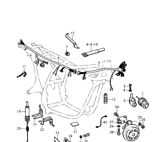
According the the parts manual it looks like the wiring harness should be installed on the right side of the bike, or… not, right side must be wrong. I’m told it right is right, but based on feedback with images I have only got photos from GT380 owners with the wiring harness on the left side of the frame, and it’s the same on my GT750 too. The drawing above must a guidance of how the wiring are connected, not which side it’s fitted.
Based on photos I have got I have some idea about how it should be done. Some advice can also be found on YouTube, but you can’t trust them. Some might be right and some are wrong, and others are horrible wrong.
So, to summarize: I’m not sure, and in some case I don’t have a clue, but I have to start and will use common sense when I have to make decisions. I think a look at mye GT570 will be at a good help. As long as I make it all in compliance with the wiring diagram it should be fine.
Connectors and tools:
I bought a kit from China with a lot of different type of connectors + the crimping tool needed.
In addition I got hold of the upper and lower wiring harness and only need to make some few extra cables to fit into the harness.

The cable from the alternator is already done, please see my previous post. The same for the cable from the ignition electronics (the points )
Next up was the battery cable. That became a bit tricky. Was not able to find the old cable anywhere and how to make a new one. The corresponding connector is made of rubber and how can I make that ? Same procedure as before. I drew the part in Fusion360 and fired up my 3D printer with rubber resin. And here is the result:

I found a picture of the cable on internet and did the measurements on the mating connector from the wiring harness. After printing the part I glued the terminals and added heat shrink to the wires.
The STL file for printing can be downloaded for free:
Next step:
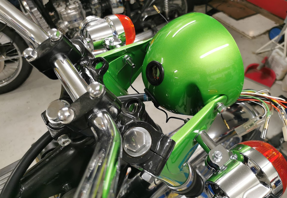
I inserted the main cable for the upper harness through the lower hole in the headlamp and the upper hole will go to the clocks and and switches on the handlebar. I will use adjustable cable ties for clamping the cable onto the frame so I can easy move and do changes as I continues with the wiring.

That’s enough for today. Will continue another day 🙂
Another day:
Still winter in Norway and I will spend some time in the Man Cave to do some wiring:
Still not sure how to lay down the wiring, but I give it a try and use reusable zip ties for an easy adjustments.
Head lamp wiring loom:

Pushing all the wires back into the headlight house to free up as much space as possible. Will be a tight fit later on when the headlight shall be mounted.
Hmm, something is wrong… The blue connector is not part of the schematics. Can it be for a later model with gear indicator ? No, the color code is different.
Some minutes later: Mystery solved, see the picture below:

The blue connector is for all of the small lamps in the clocks. According the the schematic it should be individual connectors, not a common one for all of the lamps. Anyhow, now I know how to do the wiring. It’s more easy too with one 6-pins connector, but why is it not part of the wring ?
Phuu, for a while I thought the main wiring loom was wrong. Well, a bit wrong. It’s not the wiring loom for the J-model and not for the latest ones either. Not a big deal since I know how to wire it and have the tools and parts to make the mating connectors.
Instruments bulbs:
One of the bulbs sockets looks horrible, and the wiring is in a bad shape as well.


I think I order new sockets and make a complete new wiring. If so,I have to 3D print the rubber cover too.
When it’s done, it will be a separate post about how I did it. I can’t put this old and ugly bulb loom back into the lovely bike.
Clamping to the frame:

Photos from the wiring layout:

Tried to lay the wiring close to the frame away from the air filter and other parts to be mounted later.

The wiring loom is quite stiff and to avoid too much bend I ended up laying down the cable as the picture shows. Probably not like the original, but I think this will work fine. But doing so, the fuse holder will fit better on the right side, close to the tool box, but why not?

I will 3D print a bracket for the fuse holder. The fuse holder is not the original, but close to. A 20A fuse.
Grounding:

Make sure the threads are clean without any paint to ensure a proper grounding.
Less questions, all the wiring are now sorted out :

The upper wiring loom I bought deviate from any standard GT380 wiring, it has some extra connectors.
Extras:
In addition to the 6-pins blue instrument lamps connectors there are two connectors with Gray and Black/white wires. for instruments lights ( tachometer and speedometer light)
One red wire with +12V, direct from the battery + pole and one extra GND wire. Can be used for alarm system or a charge port to the battery.
One green/yellow wire in the same connector going to the ON/OFF switch. Not in used for my J-model.
One brown wire. The same wire as going to the tail lamp. This wire will also be at power it the ignition switch is turned to parked position.
On/off switch:
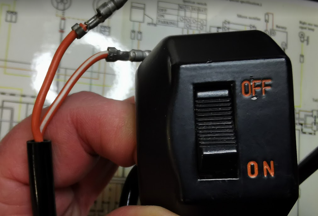
The on /off switch is a bit difficult to spot on the wiring diagram, except from the GT380B wiring. The color code is quite simple. Orange is the +12V after the ignition switch (red before the ingnition switch). The orange/white is the +12V to the coils and the bike will of course never run if this switch is turned off. According to the GT380J wiring it’s the orange/white wire changes to solid organge from the switch connector and down to the coils, but not on later models. A bit annoying and I’ve seen several variants of the J-wiring diagrams. Not easy to know what is correct.
A summary of the color codes:
Red (R): The +12V from the battery through the 20A fuse.
Orange (O): +12V after the ignition switch
Orange / white (O/W) 12V + after the ON/OFF switch. Turn on /off the voltage to the coils. Note! only orange wire on earlier models (According to the schematics)
White (W) : Brake lamp wire.
Brown (BR) Tail lamp.
Gray (GR) Instruments lamps
Blue (BL) Neutral position switch. The indicator lamp will light if the wired is shorted to ground.
Light Green (LG) Right indicator lamp.
Black (BK) Left indicator lamp.
Black/white (BK/W) GND (Ground, connected to the frame)
Light Blue (LBL) Turn signal relay wire.
Yellow in the rear wiring (Y) 3 phase AC voltage
Yellow in the front wiring (Y) High Beam Head Lamp.
Note: The Gray and Brown wires will be shorted by the ignition switch in run position and both the indicators lamps and tail lamp will light (if the main light switch is on). If the ignition switch is left in parked position the orange and brown wires are shorted and the tail lamp will light (regardless of the main light switch).