Speedometer / Tachometer assembly

Time to start the assembly process, four years after it was taken apart. The following days and weeks will show if I miss something. Some parts have already been 3D printed new or bought new.
Starting with the bracket:

All the rubber parts where stripped off and I think all of them can be reused. The bracket got sandblasted and painted.

Remounted the greenhouse tent I used when painting the frame. Ready for new paintworks to be done.

First one layer of primer.

Then, two layers of paint.
The tent will soon be upgraded with ventilation since it will be used for bigger parts as well. An oven gave a nice temperature inside the tent.

Rubber parts mounted.
The paint finish could have been better. Perhaps I had to high temperature while spraying? I don’t care since this is a non visible part, covered by the clocks. Now it’s well protected against rust.

Inner parts were painted and glued to the mounting plate.

The rubber hose was made from an old rubber tube.

I made a test fit using the new 3D printed part and also cut a new glass …. but not sure.

Ended up using the old ones from 1972. They have some cracks but seems to fit well after all.

Mad a rubber seal from the old rubber tube and glued onto the cutout in the speedometer housing.
Note! Previous owner has made an ugly cut out to be able to fit the speedometer. That’s not needed if you mount the speedometer without the rear metal disk. Thereafter you mount the disk. But now it’s done I don’t care.


On this part I used textile tape instead of rubber.

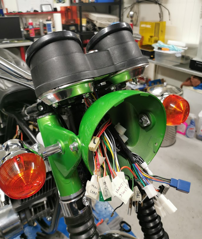
The clocks need to be glued to the inner housing. I prefitted to the bracket and made a mark to be sure it’s all aligned before gluing.

Glued and all the lamps are mounted ( and tested)

The upper rubber covers are quite loose and will be glued before I get the bike on the road.
the red lamp in the middle was meant to give a signal above 80km/h and is not in use. I will use it as an indicator to alarm if I forget the retrack the side stand.