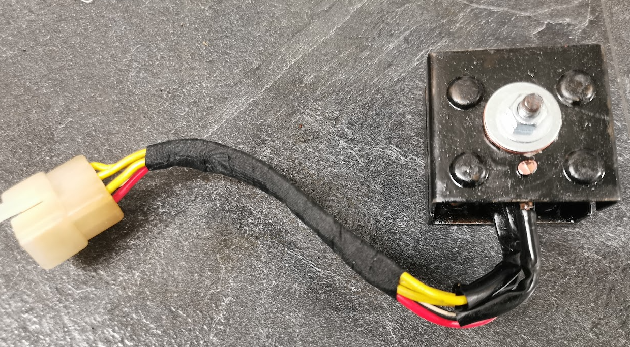
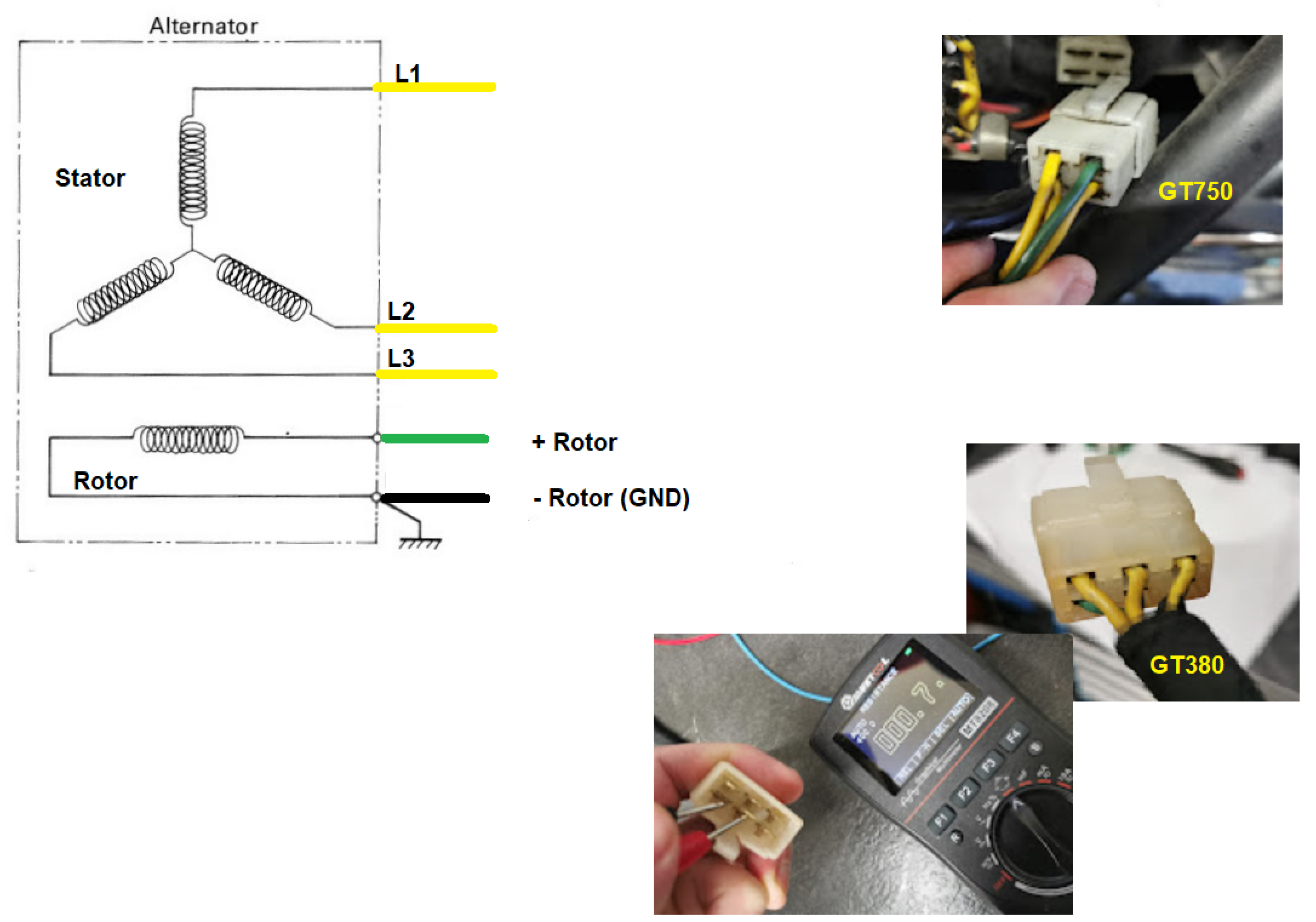
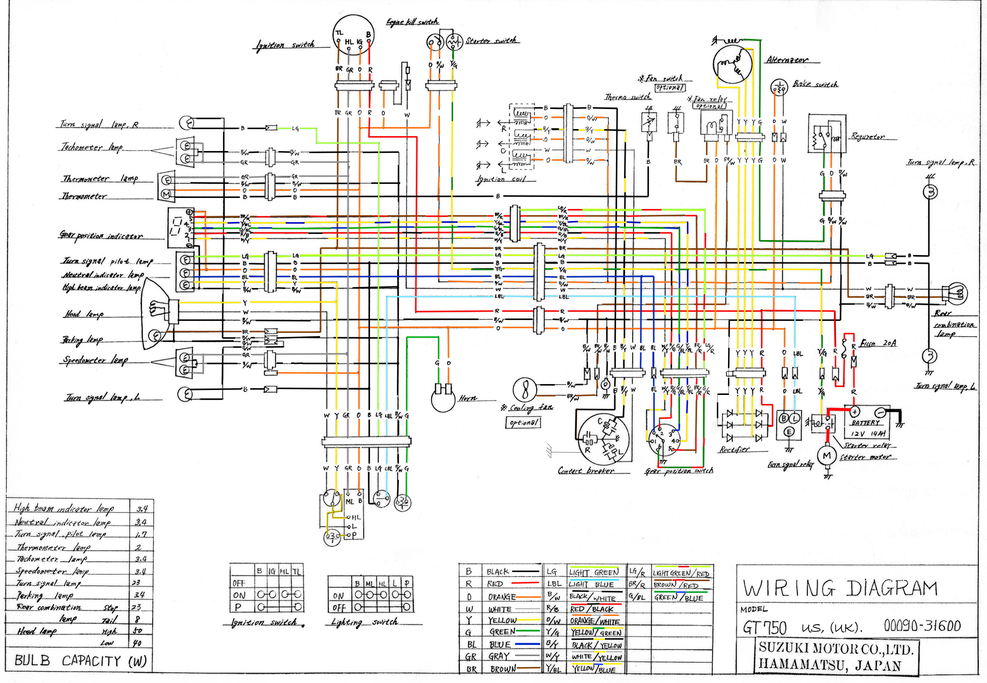
Browse Category: Electronics

Rectifier

GT380 schematics

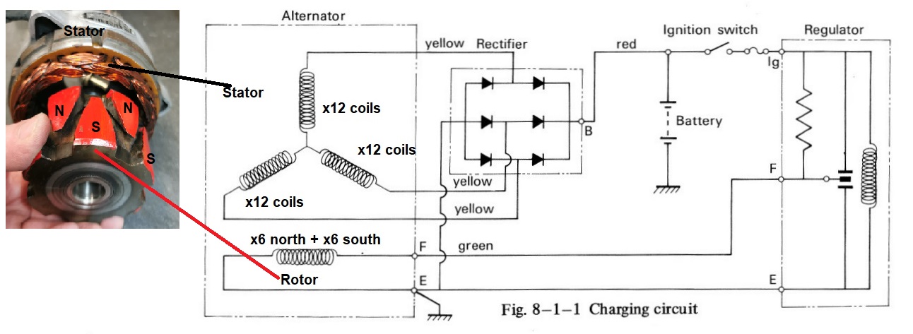
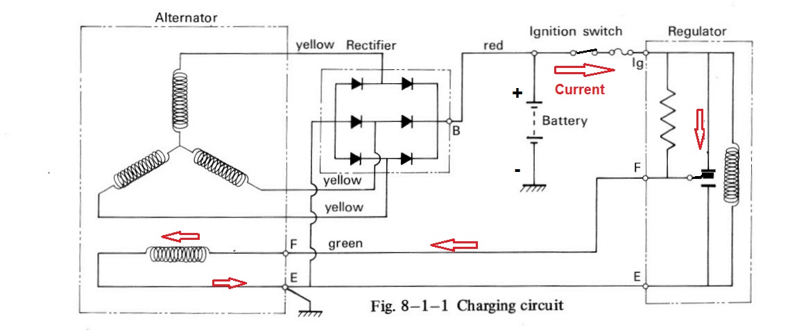
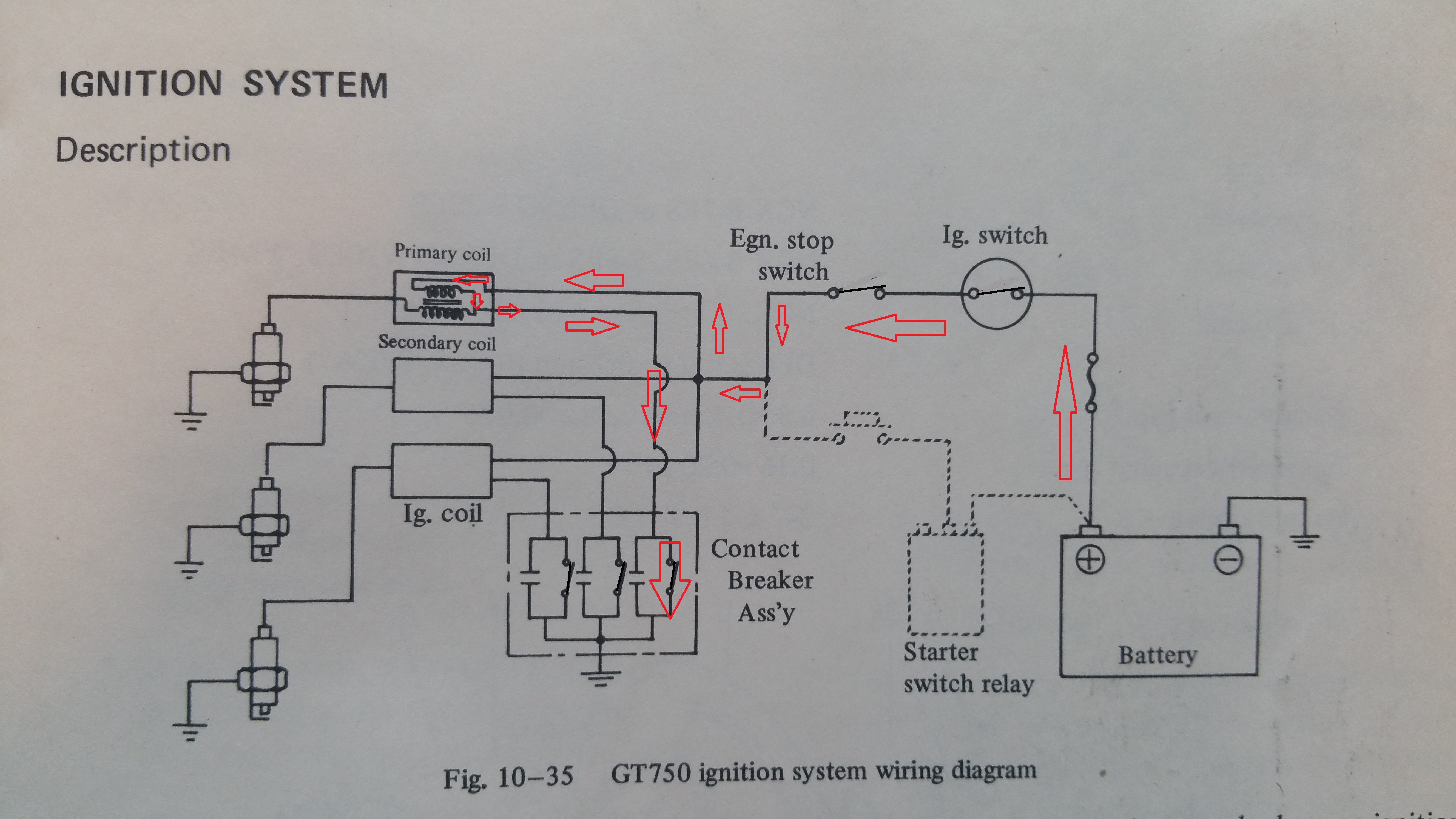
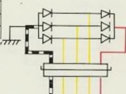
The figure above is a copy from the wiring diagram. It shows the 3-phase rectifier with three yellow wires as AC input and the plus (red wire) and GND(ground 0V black and white wire) as DC output.
The wiring diagram also shows the housing (one of the heatsink) is grounded.

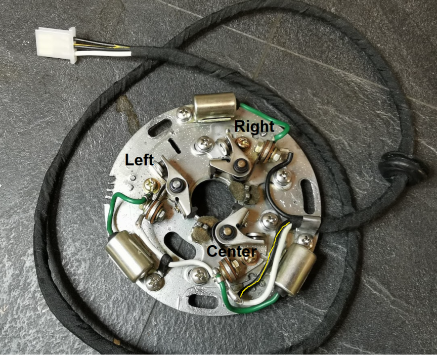
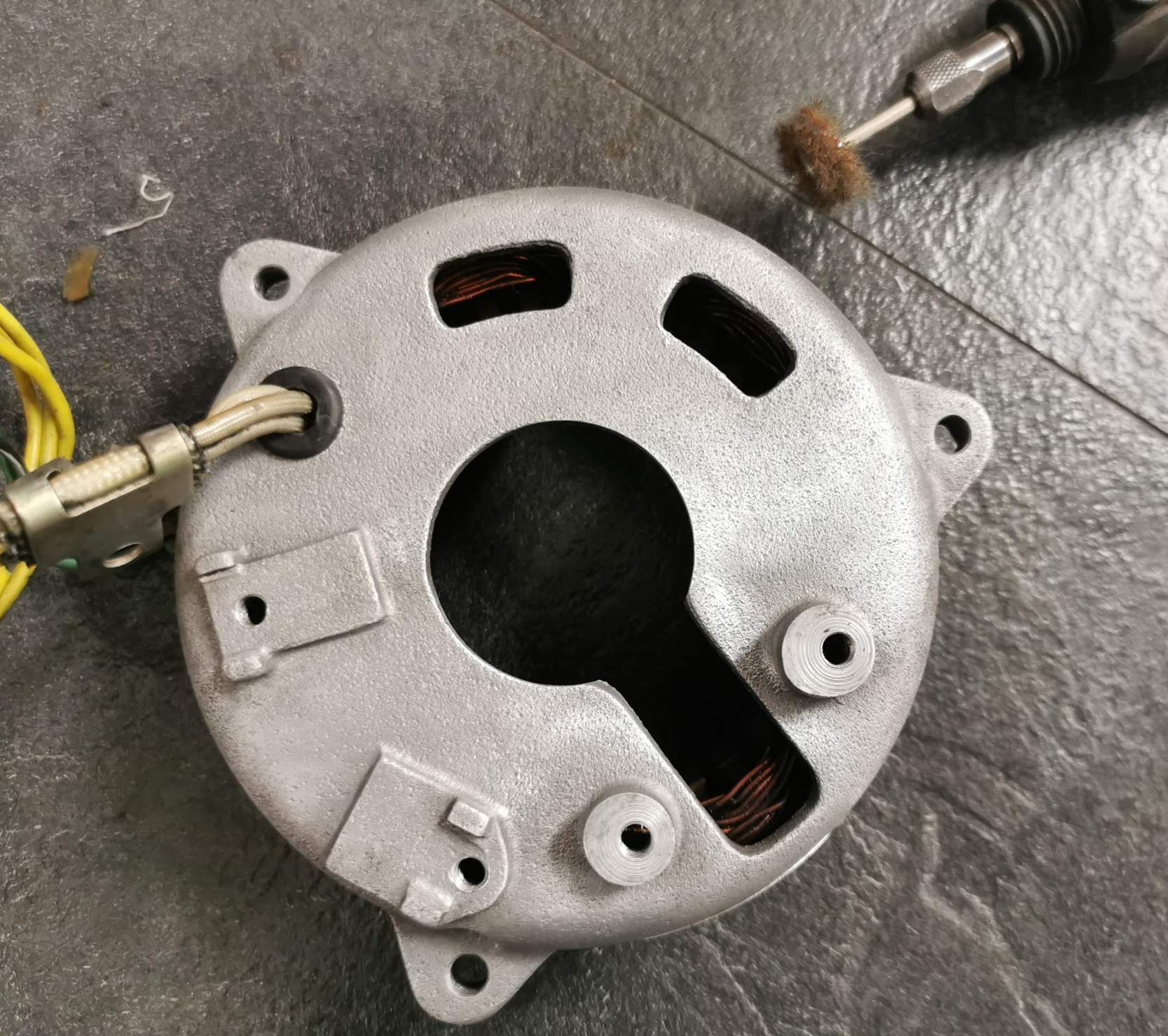
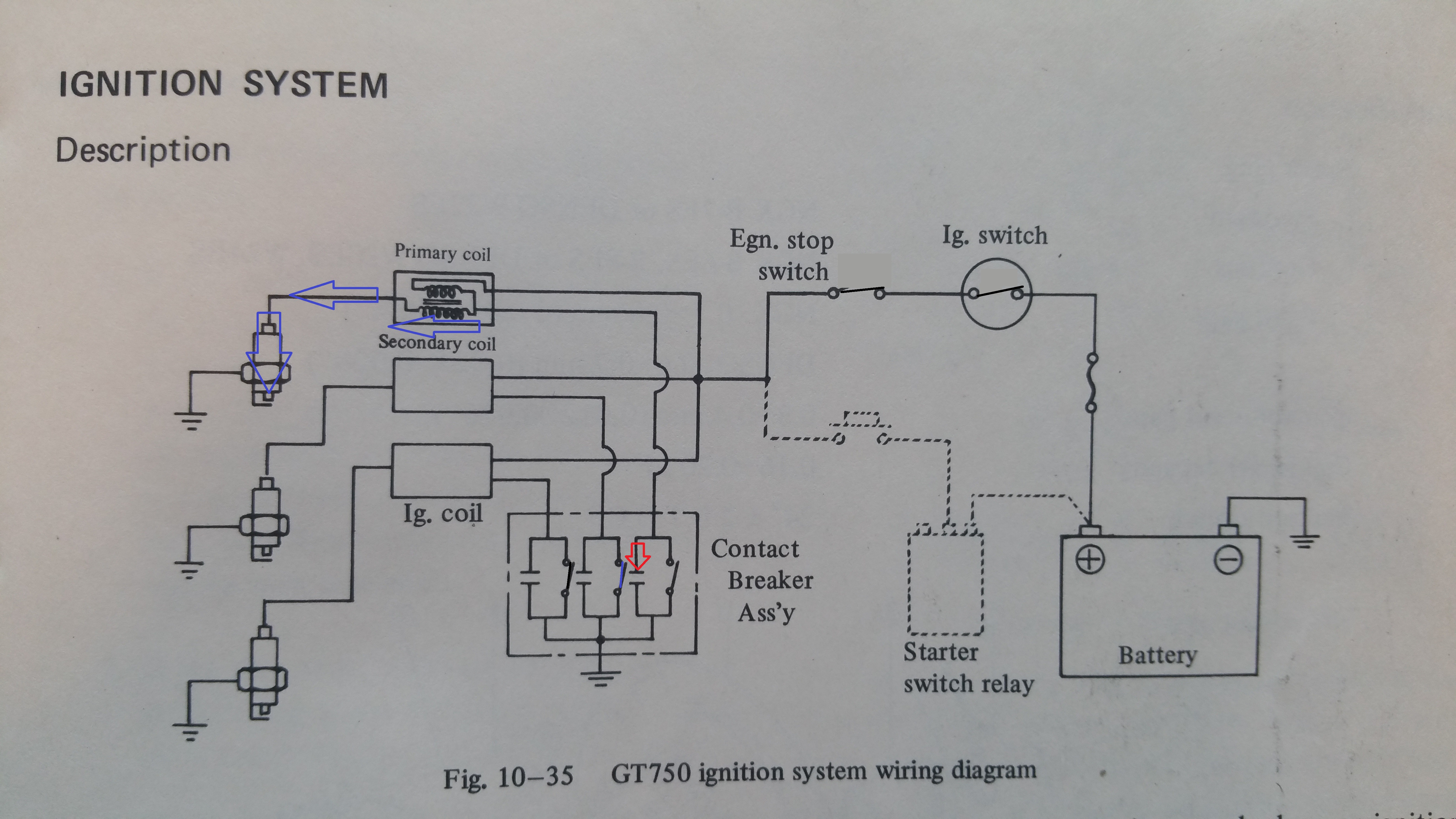
Note! I had a look on my GT750A model. An other type of rectifier (the smaller one) and the black and white GND wire is missing. All the grounding is done direct through the mounting bolt. Only four wires, three yellow and one red to the connector. A bit confusing, because the detailed wiring diagram for GT750 shows the GND wire, but not in the owners manual for GT750A. I assume it’s done different from 72-77 models.

GT750A version, no black & white GND wire.

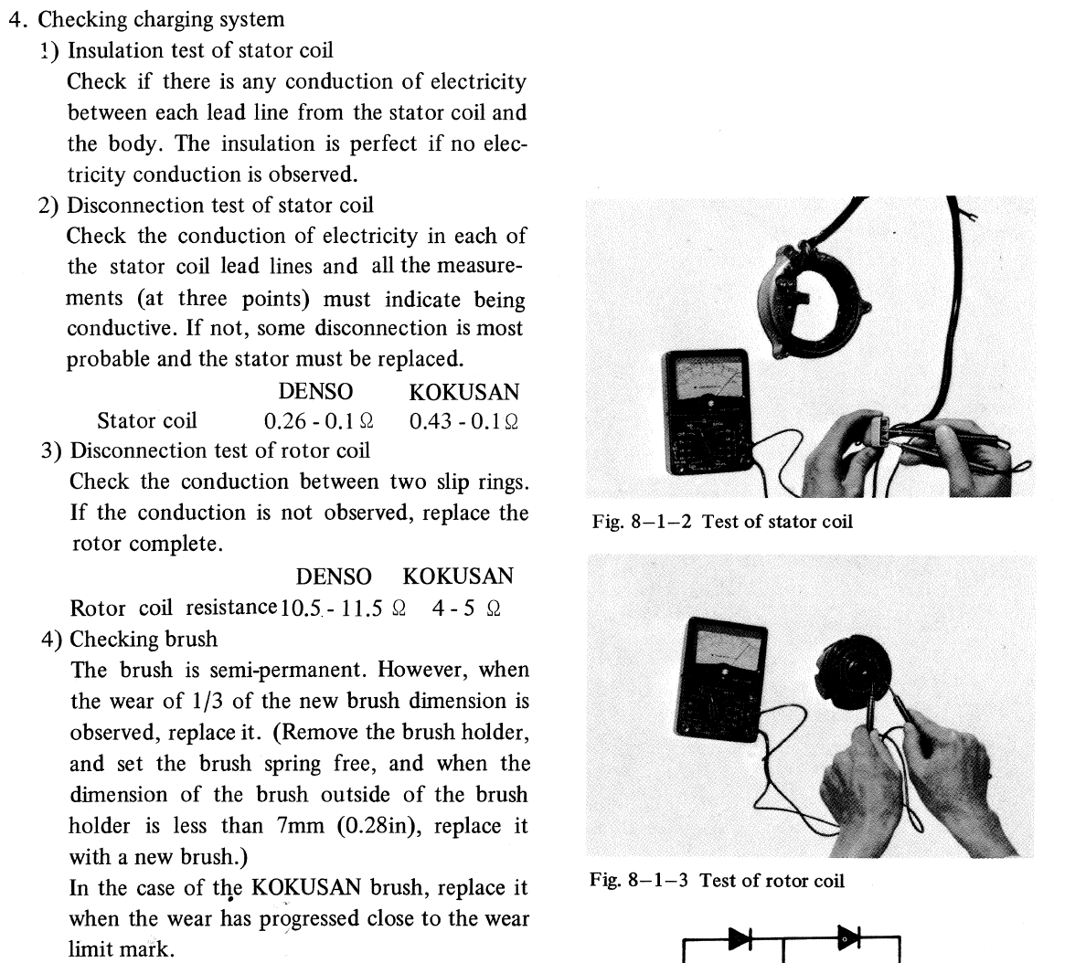
If you are uncertain how the rectifier works with all 6 diodes, please review my previous post about the alternator for GT750 and GT380. There you will also find link to YouTube explaning how it all works.

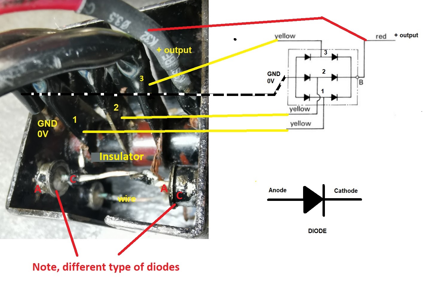
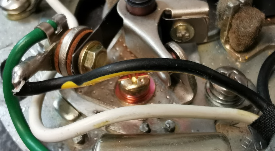
The rectifier in the image above is from the J model. You can might find a different package on later models with smaller heatsink, but they all works in the same way.

You have six diodes, three with the anode connected to the case and three diodes with the cathode connected to the case.

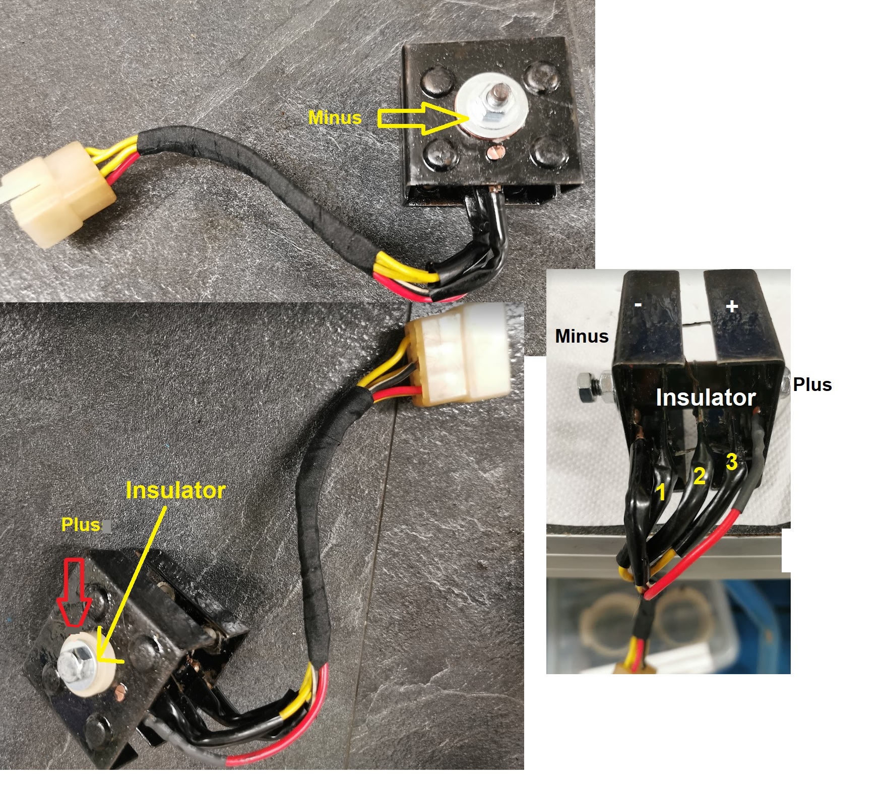
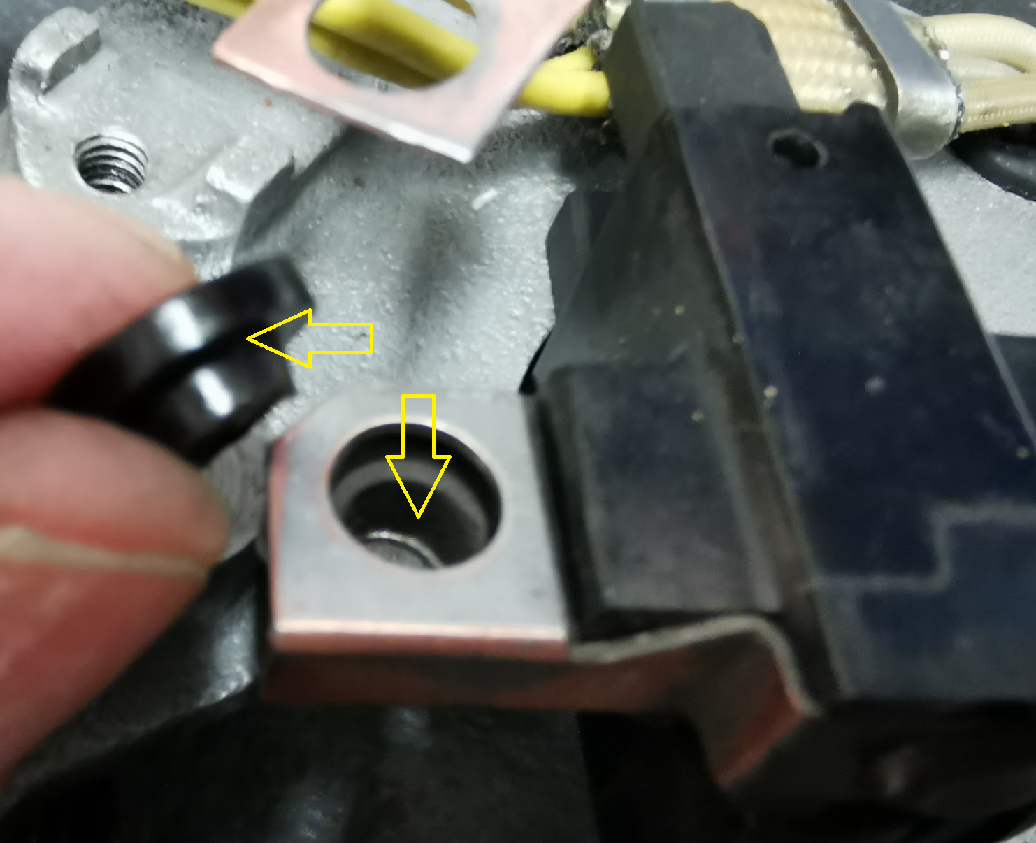
Please note, the rectifier has the heatsink splitted in two parts. One is the pluss output ond the other one the minus output (GND) . If you scratch off the pain from the positive heatsink and by accident short the heatsink to GND you short all of the voltage to ground on your bike. Note! the heatsink is connected to plus, not the bolt. The image shows how the bolt going thrugh is insulated. I did a small mod using making the insulator in peek material to improve the design a little bit.
The other part of the heatsink shall be grounded to GND according to the schematics. Mine was not and I’m not sure if it was wrong mounted or it is common not to do do. Anyhow, both options will work, but if not grounded all of the current to GND has to go through the black and wire to GND. I did it in my way and made better connection to GND from the heatsink.

Remember to remove paint to achieve a proper connection to GND.

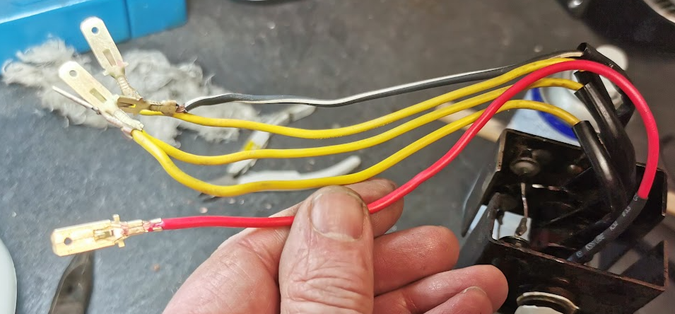
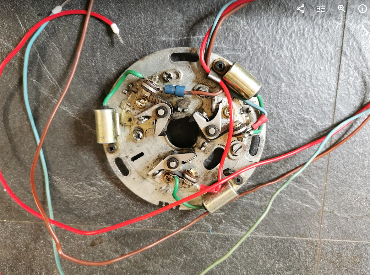
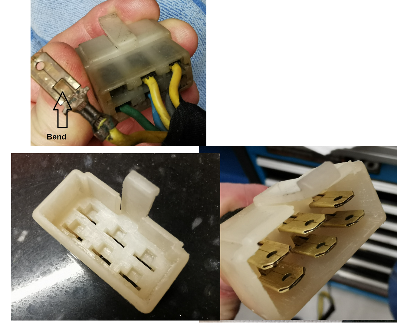
All of the connectors where polished and the red wire who was broken got replaced with a new wire and connector.

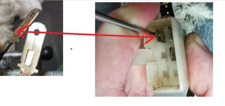
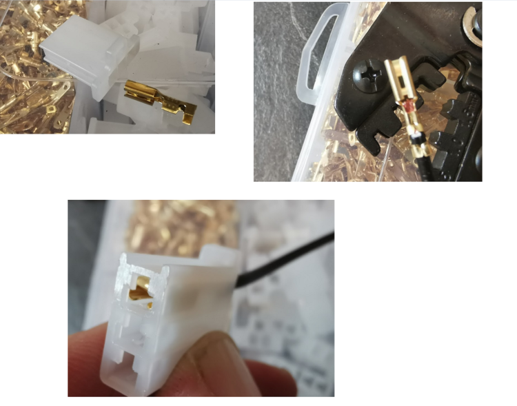
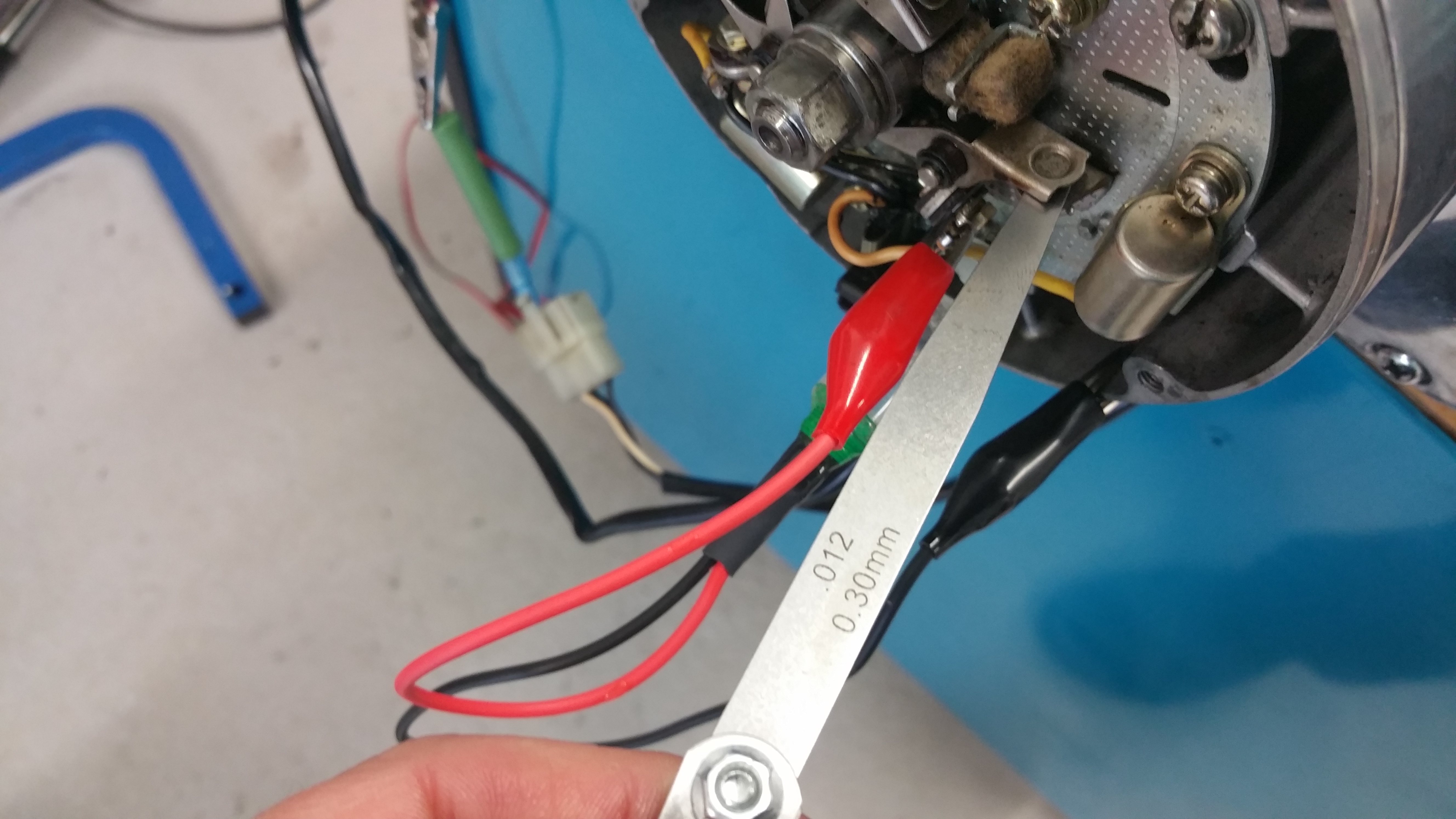
To remove the terminal from the connector, use a flat screw driver to bend the lip down and pull the terminal out from the rear side. Remember to bend the lip back to normal position when inserted.
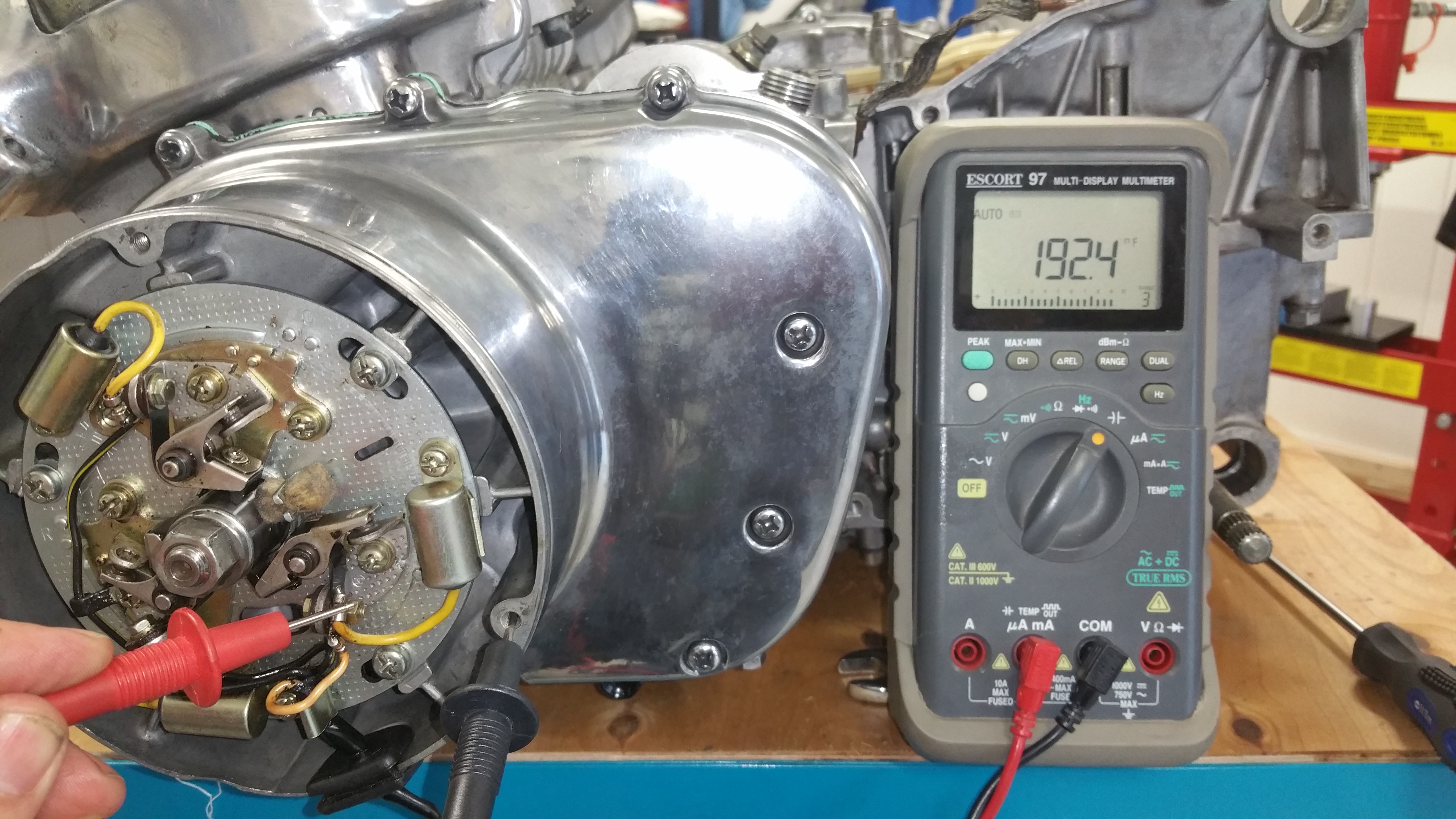
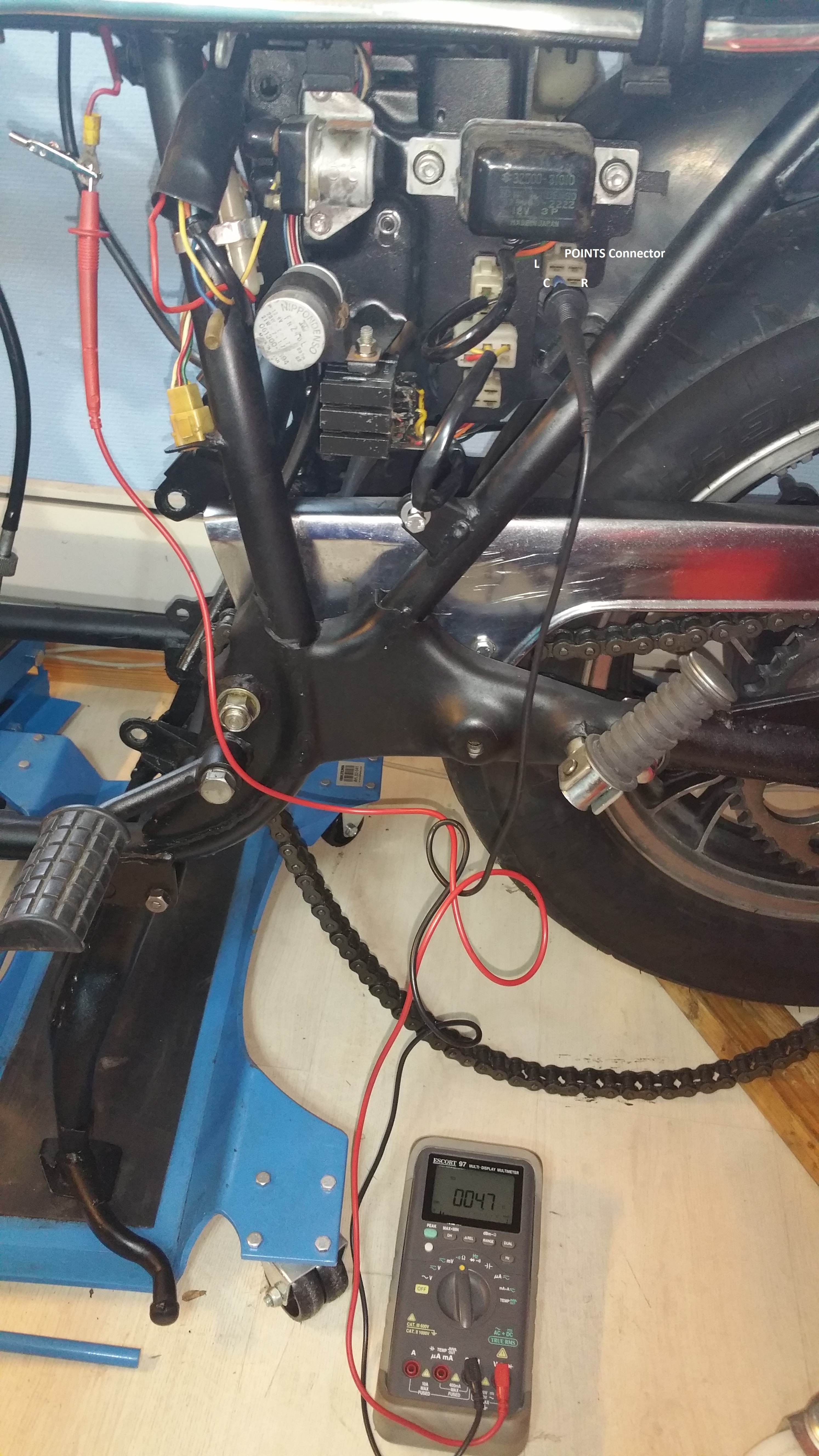
Diode testing:

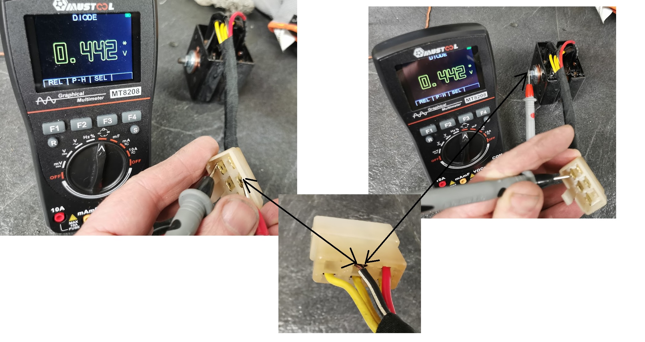
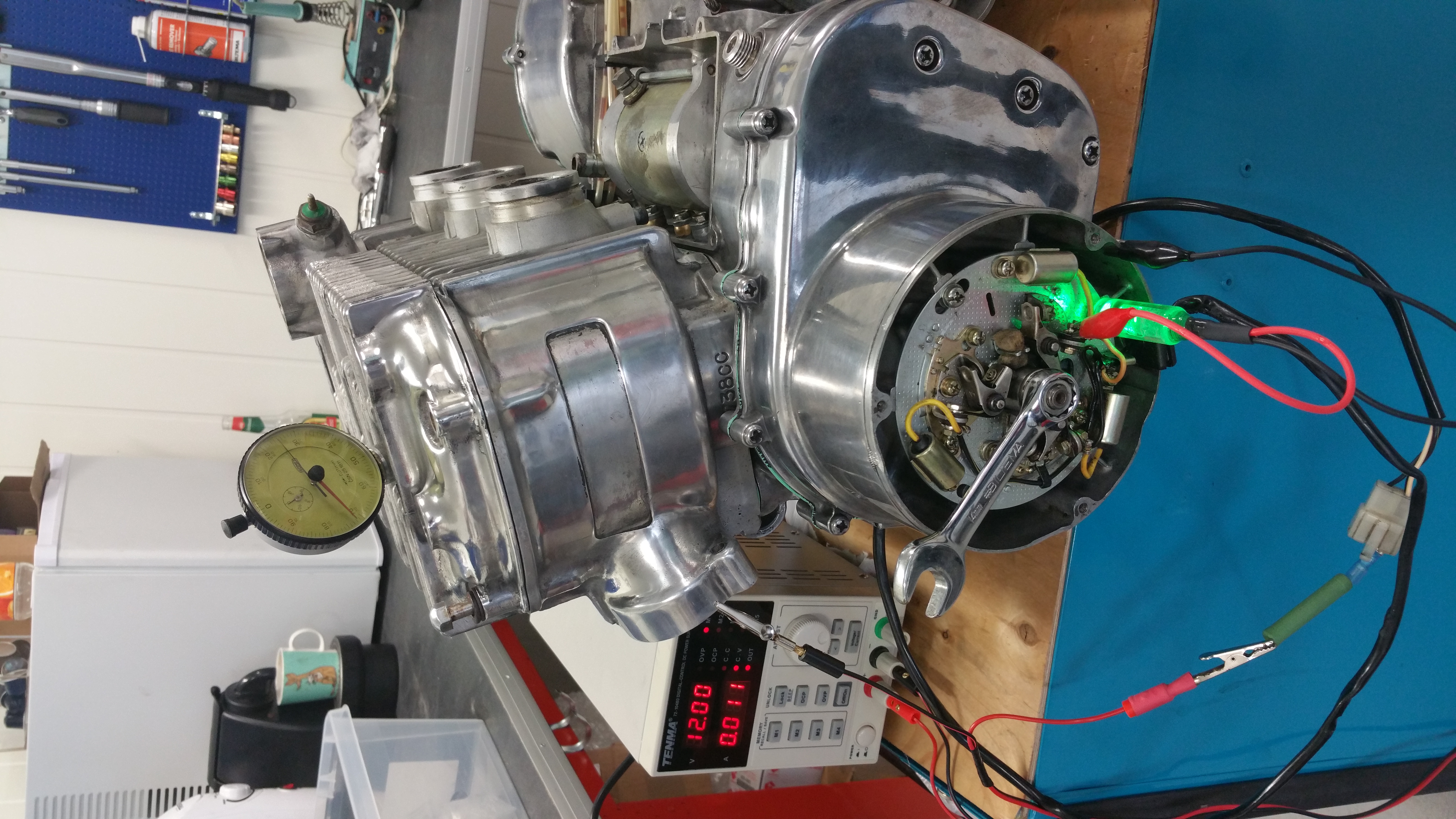
When using a multimeter for testing, switch to diode testing and do the measurements. Positive terminal(red test lead) on the anode and negtive terminal (black test lead) on the cathode. Measure all six diodes, but keep track of anode and cathode. Since the three of the diodes have the anode to GND you can also measure to the heatsink insted of the black and white GND wire/treminal

The instruments shall give you a value for about 0,45V, and no voltage if you swap the terminals ( positive on cathode and negative on anode).

Measure all six diodes, but keep track of anode and cathode. Since the three of the diodes have the anode to GND you can also measure to the heatsink insted of the black and white GND wire/treminal.

If you don’t have any multimeter you can use a small 9V battery as input and and a test lamp at the output. When you swap the polarity on the 9V battery applying power to the yellow 3-phase input the lamp shuld still light, and do the same betwen all phases.

Done !

Contact Breaker Assembly

(Denso type)

Note: Points or breakers are the same. I usually refer to the breakers calling them points.

As mention before, my GT380J project was in a horrible state when I bought it. No exceptions when it comes to the electronics. Wrong connectors and terminals. Wrong color codes on many of the wires. The wiring for the contact breaker was a mess too and I had to make it all new according to the wiring diragram.

This is how it was, wrong wire colors, wrong type of screws, and missing connector.

By the way, be aware of the difference from GT750 to GT380. Since the points are located on the right side of the bike on GT380 and left side on GT750, they have to be mirrored. Don’t buy the wrong ones.

The left point is locked direct to the main plate and has therefore a different shape compare to the center and right point.

Where to start ? I found this picture below on E-bay and it looks alright compare to the wiring diagram.

The picture also gave me some idea of the cable length.

Connector:

I bought a kit from China with a lot of connectors and terminals making it possible to fit the corresponding connector in the main wiring harness.

Connection to main wiring:

Note, on the GT380 the connector goes directly to the main wiring, not through the connector plate as you see on the GT750.

I was not able to find a black wire with yellow stripe, and as you see, I painted the yellow stripe to get the color code correct.

Left point: White

Center point: Black and yellow

Right point: Black

How to fit the contact breaker and adjust the timing will come in a later post.

Alternator for GT750 and GT380

The explanation below will be valid for both GT380 and GT750. The alternator wiring for GT750 can found on page 94 in the service manual and on page 44 for the GT380. It’s very well written and explained in the manual, but I will do it in my way and perhaps it can give you a better undrestanding of how it all works. Both manuals can be downloaded from the documents category on my blog.

Wiring diagram from the service manual:

I will use images and measurements from DENSO parts, not KOKUSAN. The differences are explained in the service manuals. The figure above from the service manual is a simplified schematics. The alternator has 36 coils (12×3) in the stator and 12 coils in the rotor (6 north poles and 6 south poles). Please see the figure below:

Abbreviation and definitions:

DC: Direct Current

AC: Alternating Current

DC Voltage : A voltage with fixed plus and minus polarity and the current will flow from plus to minus if you have a closed circurit. ( the flow of electrons are the oposite way, from minus to plus ) Ex: The 12 Volt battery on your bike is the DC voltage source and the minus pole is grounded to the frame.

AC Voltage: An alternating voltage where the polarity changes with a given frequency. On your bike the rpm + the numbers of coils in the rotor and stator will define the frequency.

Stator: The stator in the alternator above is a 3-phase generator giving 3-phase sine wave voltages phase shifted at 120 degrees.

Rotor: Ther rotor is a rotating DC controlled magnet giving magnetic flux varation to make induction of voltage at the stator windings (coils).

Regulator: The voltage regulator in the diagram is a ordinary relay with 3 positions. In postion 1 and 2 DC current will flow from the + pole on the battery through the rotor windings and down to ground.

Position 1: No restriction of the current into the rotor windings. If the voltage is too low to activate the relay, it stays in position 1, shorting the resistor. The rotor will get the maximum current and gives the maximum flux from the coils.

Position 2: The voltage has rise and ther relay activate and and the resistor be in series with the rotor windings since the short is gone and the current has to flow through the resistor and the rotor current goes down causing less flux in the coil.

Position 3: High rpm of the engine giving high voltage and the relay goes all the way to the lover postition, shorting the rotor, no current will flow in the rotor windings. There are still some flux in the iron core of the rotor and induction of voltage in the stator will still goes on. If the voltage get lower agian, the relay will go back to stage 2 or 1 and send current into the rotor windings (coils) and keeping a steady voltage to the battery.

3-phase rectifier: The rectifier turns the AC votage into a DC voltage by using 6 diodes to turn the minus part of the sine wave into a posive part. Since all three phases are appers at a different time (due to the phase shifting) the output from the rectifier will be a DC voltage with very little ripple voltages compare to a single face rectifier.

Location of parts:

YouTube links:

How an alternator works: https://www.youtube.com/watch?v=tiKH48EMgKE

How a 3-phase rectifier works: https://www.youtube.com/watch?v=-XUsu08Farw

How to test a diode: https://www.youtube.com/watch?v=mMXDa5hVzXA

Diodes explained :https://www.youtube.com/watch?v=Fwj_d3uO5g8

Refurbishing the alternator:

The alternator covered in oil and dirt, and the wiring was in a bad shape. When I was finished it looked like this:

Note: The blue wire is for the neutral indicator switch. When the switch ground the wire the indicator lamp will light.

Some of the steps:

Parts removed and the stator housing was cleaned and polished using a rotating brush.

All the terminals were polished too. Don’t forget to mount the isolation cap when assembling the brushes. If not you will short the positive pole down to ground.

The old sleeve was brittle and had to be replaced. I went for a more modern flexible type and wrapped around a textile type of tape able to withstand 150 deg C.

Bend down the locking lip of the terminal and pull out from the rear side. I did a lot of tips and tricks from YouTube how to remove the yellowing of the plastic. Used both ultrasonic cleaner and hydrogen peroxide + UV light. Not perfect, but it became better. Polished the terminals and mounted it all back in place.

Soldering:

You can replace all the wires, but I didn’t. Some of the wires were extended to make a proper wiring harness with correct lenght on all the wires. To make the soldering more easy I wrap a single wire around the wires to keep them both in place during the soldering. Added a double set of heat shrink tubings.

Mounted on the bike:

Measurements:

Stator windings:

BikeL1-L2L1-L3L2-L3
GT7500,7 ohm0,7 ohm0,7 ohm
GT3800,7 ohm0,7 ohm0,7 ohm

Rotor windings:

BikeBetween green and black/white wire on GT380 and between green and ground (frame) on GT750
GT7505,8 ohm
GT3806,8 ohm

On the stator windings all measurements are done between the phases, the yellow wires.

Please notice the connectors. On the GT380 there is 6 pins and only 4 pins on the GT750. The ground (black/ white wire) and neutral indicator (blue wire) is missing. To measure the rotor on GT750 you therfore have to measure from the green wire to any GND points on the frame.

Note! If you measure rotor through the connector you will also measure through the brushes. If you get a very hight value you have bad connections in the brushes due to dirt and oxidation. Apply 12V DC for some seconds into the rotor and it will be all OK.

Numbers from the service manual:

I find those numbers hard to belive, can’t be right. The stator coil (windings) can’t vary from 0,26 ohm down to 0,1 and be valid.

Stator windings: The resistance in the stator windings don’t change over time. It’s not magic, it’s a wire winded around a some iron core and the length and thickness of the wire will define the resistance. If you get a short between some of the wires the resistance will go down and not increase. And you will see a difference between the three phases. You will never have three identical fault in the same stator. The measurements I did gave higher resistance and were identical on both the GT380 and the GT750.

Rotor windings:

The rotor resistance I measured on both GT750 and GT380 is much lower compare to the manual. OK, one reason can be a short between windings in the rotor. But i checked all 12 magnets and verified they all had the correct Norh and South poles with the same strenght. A short giving half the resitance compare to the number in the manual would give weak magnetic field on some of the magnets. Since I have about the same measuremetns on both rotors and the GT750 is running fine and gives the correct voltage to the battery I’m pretty sure it’s all OK. Why the numbers in the manual are so differnt, I really don’t know.

Headlamp

Headlamp housing mounted:

Got a bit confused due to the drawing. It shows a headlamp bolt with flat head:

Looking up the part no and looking at images, they all had rounded heads. I took an old original Suzuki bolt. After sandblasting and nickel plating it was good as new.

Latest progress:

The wiring harness has been mounted and testet. Time for the head lamp to be fitted.

Sealed beam type of headlight. Will last for 50 more years.

Made a new connector to fit the wiring harness.

Done:

Timing adjustments GT750

Adjustment procedure for setting the correct ignition timing.

Please read previous post regarding the functional description about the GT750 ignition system. This post will cover the adjustment of the points to achieve the correct timing.


Timing crankchaft

Fig.1

In fig.1 you can see the Timing Plate showing the BTDC marker for each piston. When the marker is aligned with the black arrow at the bottom of the picture the piston is 24 deg befor the TDC (Top Dead Center ) or 3,64 mm below the top. 3,64mm for L and R and 3,42mm for C piston. This timing plate was the Suzuki original idea regarding the timing adjustments and no other equipments than a lamp was needed for doing the job. Quite simple. The points should open when the markers are aligned.

That’s basically all you need to know, the rest of it you can easy figure out by yourself…

Clamp on the Contact Point base plate with all its assembly and do the adjustment.

Some guidance can be needed. Suzuki understood after a while, the procedure using the timing plate was not accurate enough. Some extra tools can also be handy for an optimized adjustment.


Tools:

Tools2

Fig. 2

The Dial Gauge will be used to give a accurate measurement from the TDC down to the position where the points should open up (BTDC). I made my own instrument using a standard dial gauge and drilled a hole in a spark plug for mounting the gauge.  The lamp is also self made. A LED lamp with a magnet at the end for easy fastening on top of a screw or other parts which are magnetic.

Adjustments:

Timing Adjustment

Fig 3

By loosen up the three base plate screws (yellow marker) you can adjust the timing of all cylinders. This is to be done when you install the timing plate assembly for the first time after a rebuild and you know the timing was more or less correct  before the dismounting. Don’t loosen up any points individually before you have checked the timing using the following procedure:


Step 1, checking the timing the old way

20160627_200351

Fig.4

In fig.4 I do the timing adjustment using an external power supply and use a resistor instead of a coil and apply the + voltage to the Left point wire (white colour wire ) When the engine is mounted in the frame and the coils are connected the current will come from the battery trough the coils ( see previous posts and wiring diagram )

The lamp is connected to the yellow wire and ground on the left circuit breaker (left point ) If the points are closed the lamp is off. As soon as the points opens up the lamp will light. Remember, the points short the yellow wire down to ground when its closed. At open position the voltage at the yellow wire will be around 12V (depending of the type of lamp )

Step 2, restore previous timing settings

Move the crank counter clockwise until the lamp lights up.  If the timing is correct the timing marker in the timing plate should be aligned, see fig.5.  Red and yellow arrow on the picture shows the markers

Marker

Fig .5

This is the BTDC for the left piston and the piston is 3,64mm below the top position ( TDC , Top Dead Center )

If this is not correct, move the crank until the markers are aligned and loosen all of the three base plate screws and move the plate until the lamp goes on and off. Secure the screws.

Now you are back to the original state before dismounting the timing assembly. Center and right points should also be OK at this stage if they were correct before the dismounting.

20160627_200405

Fig. 6

In fig. 6 you can see the position of the piston at BTDC

Step 3, adjusting the points gap

20160627_201003

Rotate the crank until you have the maximum distance between the points. Measure and verify the gap. Should be between 0,3-0,4mm. If adjustment is needed, loosen the screw with a red label in fig.3. Check this for all of the three circuit breakers. Do this before the final timing adjustment. Any adjustment of the gap will also influence the timing and the timing has to be rechecked.

Step 4, accurate timing adjustment

As mentioned before, Suzuki recommend not to use the timing plate as the final adjustment. A dial gauge is needed to get this correct.

20160627_200644

There are different type of dial gauges on the market. Suzuki has a special one with a zero function. I use a standard type but capable to measure several mm. Whatever procedure you decide to use, this is important : Don’t count mm while rotating backwards. From the BTDC rotate the crank the normal direction (counter clockwise). The distance from BTDC to TDC is 3,64mm for the left and right pistons and 3,42mm for the center piston.

If the timing is wrong, rotate the crank until the distance is correct and loosen the points shifting plate ( two screw with green label in fig.3) Move the plate until the lamp goes on and off. Fasten the screws and repeat the measurements. Do this for all of the three circuit breakers (points)


IMPORTANT NOTE !

The procedure above is not compliant with the procedure in the Suzuki service manual, page 94.

Suzuki use a battery driven lamp / buzzer to measure the points. The leads out of such a device gives light / sound when you short the leads. The points does this short and the lamp will therefore go out when the points open up and will light when the points are closed, exact the oposite function of a test lamp using the voltage from the battery on the bike. One more time, opposite light function compared to my description above.

If you didn’t get this, read it one more time and give it a try on the bike.

Coils and capacitors

In this post I will try to give basic information about the electronics in the ignition system. The Suzuki service manual refer to two of the key components as Condenser  and Coil. In fact , that’s a bit wrong. The condenser is a capasitor and the coil is a transformer made of two coils, one for the primary side and one for the secondary side.

Condenser / capacitor

Capacitor

Fig.1

The word condenser is common to use on components able to store or convert energi (ex:converting gas into liquid)  but in electronics this device is more referred as a capacitor and I will use the word capacitor or CAP in the rest of my posts.

In fig 1 you can see three caps connected above each circuit breaker to protect the points in the breaker. One for each cylinder , Left, Centre and Right.

Ignite0

Fig.2,

In fig 2. you can see the electrical connections of the capacitor. There is only one wire connected, the yellow wire as shown in fig.1. Pin2 in the schematic symbol is internally connected to the body of the component and will therefore be grounded when mounted at the assembly plate. The schematics in fig.2 is only for one cyllinder. All together we have three coils, three circuit breakers and three capacitors, but one battery.

A capacitor consist of two metal plates (metal foil) with an electric insulated material in between. The Suzuki type is rolled and put in a can. That’s the reason for the shape of the cap.

If you apply voltage to a cap you will charge up the cap with current until it has the same voltage as you apply. Almost the same as a battery except from the speed. You can charge and discharge thousends of times within a second. The frequency can be many kHz. If we go above Mhz the performance will change and this type of cacitor will become a coil, but don’t worry, I will not discuss that now.

The units for measuring a cap is Farad. The value of the Suzuki cap should be in the range of 160-220 nF. That’s the same as 0,000000160-200 Farad.

How to measure the value :

If the capacitors are mounted and installed at the bike do the following:

Disconnect the wiring harness of the points from the connector, see fig.3


OLYMPUS DIGITAL CAMERA

Fig.3


20160625_210418

Fig.4.

Make sure the point is open and not closed. If the point is closed you have a short in paralell of the cap.

Use an instrument capable of measuring CAPACITOR. Connect the red test lead from the CAP output to the yellow wire on the capacitor. The black lead to any part at ground level. In fig. 4 the value is 192 nF and is a valid result.


COIL
As mentioned in the beginning of this post the Suzuki coil is actually an electromangnetic transformer and contains two coils. And three of those transformers is needed, one for each spark plug.

What is a the function of an electromagnetic transformer ?


transformer

Fig.5

Answer: On the primary side you apply a AC voltage and the windings around the iron core set up an alternating magnetic field. At the secondary side the magnetic fields are throwned across the windings. Whenever an inductor or a wire sees a varation in a magnetic field we have induction of voltage across the wires. And the bulb in fig. 5 can light up. The ratio on numbers for windings define the voltage. If you have 10 times more turns  on the primary side compare to the secondary side, the voltage will be 10 times lower on the lamp. And opposite, in the GT750 coil we have more windings on the secondary and transform the voltages up many times


And don’t be sad if you don’t understand why. Einstein didn’t understand it either. No one does, it’s only a fact of physics. And it only happen if we apply AC (alternated voltage) giving an alternated magnetic field. A static magnetic field does not induct any voltage at the secondary side.

In other words, a 12V DC battery gives no voltage at the secondary side. Stop !, that’s what we have in the GT750 electronics, a DC battery and a transformer. Yes, and you don’t get any voltage on the secondary side until you…..cut off the current with the circuit breakers. That’s what we use the points for, cutting a DC current into pieces , making a conversion from DC to AC.


Current into the GT750 coil:

Ignite1

Fig. 6

I measured the DC resistance in the primary side coil to about 4,7 ohm. 12V divided on 4,7 R gives about 2,5 Amps into the coil. This gives a solide magnetic field in the coil but no voltage at the secondary side. When the camshaft hit the circuit breaker and open up the points, the current are cutt off and the magnetic field collaps. This is the change in the field that gives the high voltage at the secondary side. The voltage across the opened point is also very hig but the capacitor in paralell charge up and protect the points from getting worn.

This sequence is also explained in the post “Ignition circuitry

This is meant to happen 24 deg before BTDC ( Before Top Dead Center ) A detailed explanation of the timing adjustments will come in a separate post


How to measure the coil :

Click on the image for details

Coil

Fig.7

An easy access to all of the three coils is to measure from the side panel and to the positive pole on the battery cable. Remember the signal from the meter has to go through the emergency switch and the ignition switch. I found 4,7 ohm on all of the secondary side coils.

See the wiring diagram and my previous post “Ignition circuitry


Figure 8. shows another access to the coils:

The orange wire is the common wire for all of the coils. Measure from the orange one and to the White (Left coil ) Black /yellow ( Center coil ) and Black wire for the Right coil.

connector coils

Fig.8


Ignition circuitry

The schematics shows the circuitry to ignite all of the spark plugs. This is a copy from the Suzuki service manual.

Ignition0

Fig1.

In the schematics all three points are drawn in a open position. This will never happen. The normal positon is closed and 24 deg before  pistons top position (BTDC)  the contact breaker (point) will open up if the adjustemen is done correct.

Step 1: Contact breakes are closed. 

Ignition1

Fig.2

Ig.swich and Egn.stop switch must of course be in closed position to allow current to the coils.

The red arrows in fig.2  shows how the current goes from the battery through the primary coil and down to ground through the contact breaker.The same will happen in the others coils as long as the corresponding contackt breaker is closed.

This is the reason why you drain the battery empty quite soon if you leave the ignition switch on while parking. A lot of current are going through the coils.

Step 2, Ignition

Ignition3

Fig.3

When the piston comes to the BTDC ( 24 deg before the top, 3,64mm on left and right cylinder and 3,42mm on the centre cylinder ) the contact braker open and cut off the current into the coil.

The next step is not easy to understand, but I will try to explain. Before the current was cut off it made a powerful magnetic field in the coil. When the field collapse (due to the opening of the contact breaker and cutting off the current) the change in the magnetic field will make a voltage induction many times higher than the 12V battery in the bike. This high voltage will also burn the points in the contact breaker if there where no capacitor connected in paralell. The capacitor will be recharged by this voltage and store the energy for a short perode of time. At the same time the primary side of the coil will also see the  switching of the magnetic field. The primary coil has more windings compare to the secondary and therefore transform the voltage to many thousand volts and we get the spark. See the blue arrows in fig. 3

The basic functions of coils and capacitors will be explained more in depth in a separete post.

The physical implementation and the adjustment procedure for the timing will also be explained in a separate post.

  • 1
  • 2