Alternator for GT750 and GT380
The explanation below will be valid for both GT380 and GT750. The alternator wiring for GT750 can found on page 94 in the service manual and on page 44 for the GT380. It’s very well written and explained in the manual, but I will do it in my way and perhaps it can give you a better undrestanding of how it all works. Both manuals can be downloaded from the documents category on my blog.
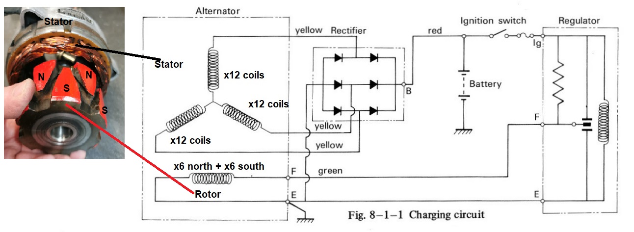
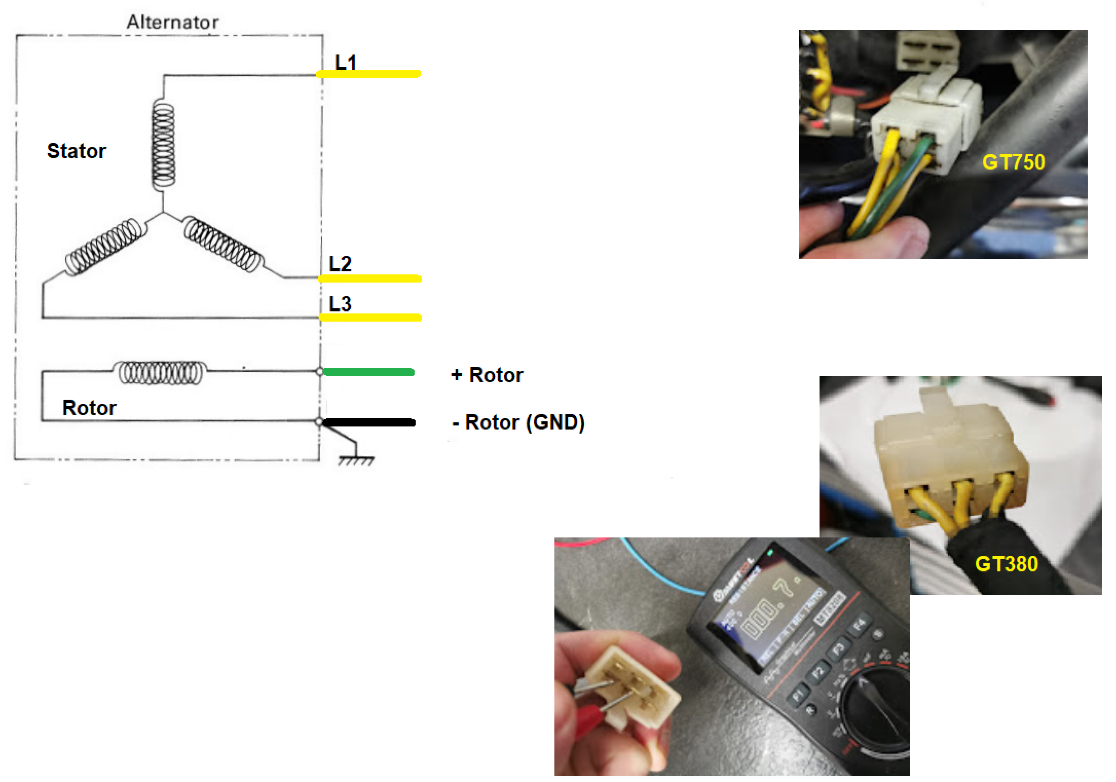
Wiring diagram from the service manual:

I will use images and measurements from DENSO parts, not KOKUSAN. The differences are explained in the service manuals. The figure above from the service manual is a simplified schematics. The alternator has 36 coils (12×3) in the stator and 12 coils in the rotor (6 north poles and 6 south poles). Please see the figure below:
Abbreviation and definitions:
DC: Direct Current
AC: Alternating Current
DC Voltage : A voltage with fixed plus and minus polarity and the current will flow from plus to minus if you have a closed circurit. ( the flow of electrons are the oposite way, from minus to plus ) Ex: The 12 Volt battery on your bike is the DC voltage source and the minus pole is grounded to the frame.
AC Voltage: An alternating voltage where the polarity changes with a given frequency. On your bike the rpm + the numbers of coils in the rotor and stator will define the frequency.
Stator: The stator in the alternator above is a 3-phase generator giving 3-phase sine wave voltages phase shifted at 120 degrees.
Rotor: Ther rotor is a rotating DC controlled magnet giving magnetic flux varation to make induction of voltage at the stator windings (coils).
Regulator: The voltage regulator in the diagram is a ordinary relay with 3 positions. In postion 1 and 2 DC current will flow from the + pole on the battery through the rotor windings and down to ground.
Position 1: No restriction of the current into the rotor windings. If the voltage is too low to activate the relay, it stays in position 1, shorting the resistor. The rotor will get the maximum current and gives the maximum flux from the coils.
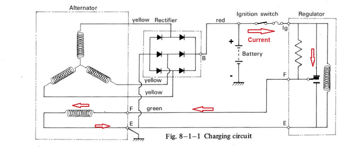
Position 2: The voltage has rise and ther relay activate and and the resistor be in series with the rotor windings since the short is gone and the current has to flow through the resistor and the rotor current goes down causing less flux in the coil.

Position 3: High rpm of the engine giving high voltage and the relay goes all the way to the lover postition, shorting the rotor, no current will flow in the rotor windings. There are still some flux in the iron core of the rotor and induction of voltage in the stator will still goes on. If the voltage get lower agian, the relay will go back to stage 2 or 1 and send current into the rotor windings (coils) and keeping a steady voltage to the battery.

3-phase rectifier: The rectifier turns the AC votage into a DC voltage by using 6 diodes to turn the minus part of the sine wave into a posive part. Since all three phases are appers at a different time (due to the phase shifting) the output from the rectifier will be a DC voltage with very little ripple voltages compare to a single face rectifier.
Location of parts:

YouTube links:
How an alternator works: https://www.youtube.com/watch?v=tiKH48EMgKE
How a 3-phase rectifier works: https://www.youtube.com/watch?v=-XUsu08Farw
How to test a diode: https://www.youtube.com/watch?v=mMXDa5hVzXA
Diodes explained :https://www.youtube.com/watch?v=Fwj_d3uO5g8
Refurbishing the alternator:

The alternator covered in oil and dirt, and the wiring was in a bad shape. When I was finished it looked like this:

Note: The blue wire is for the neutral indicator switch. When the switch ground the wire the indicator lamp will light.
Some of the steps:
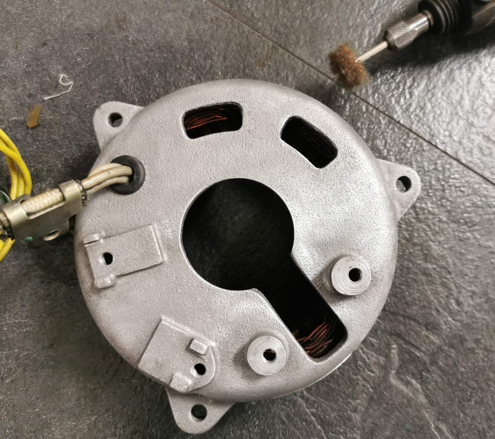
Parts removed and the stator housing was cleaned and polished using a rotating brush.
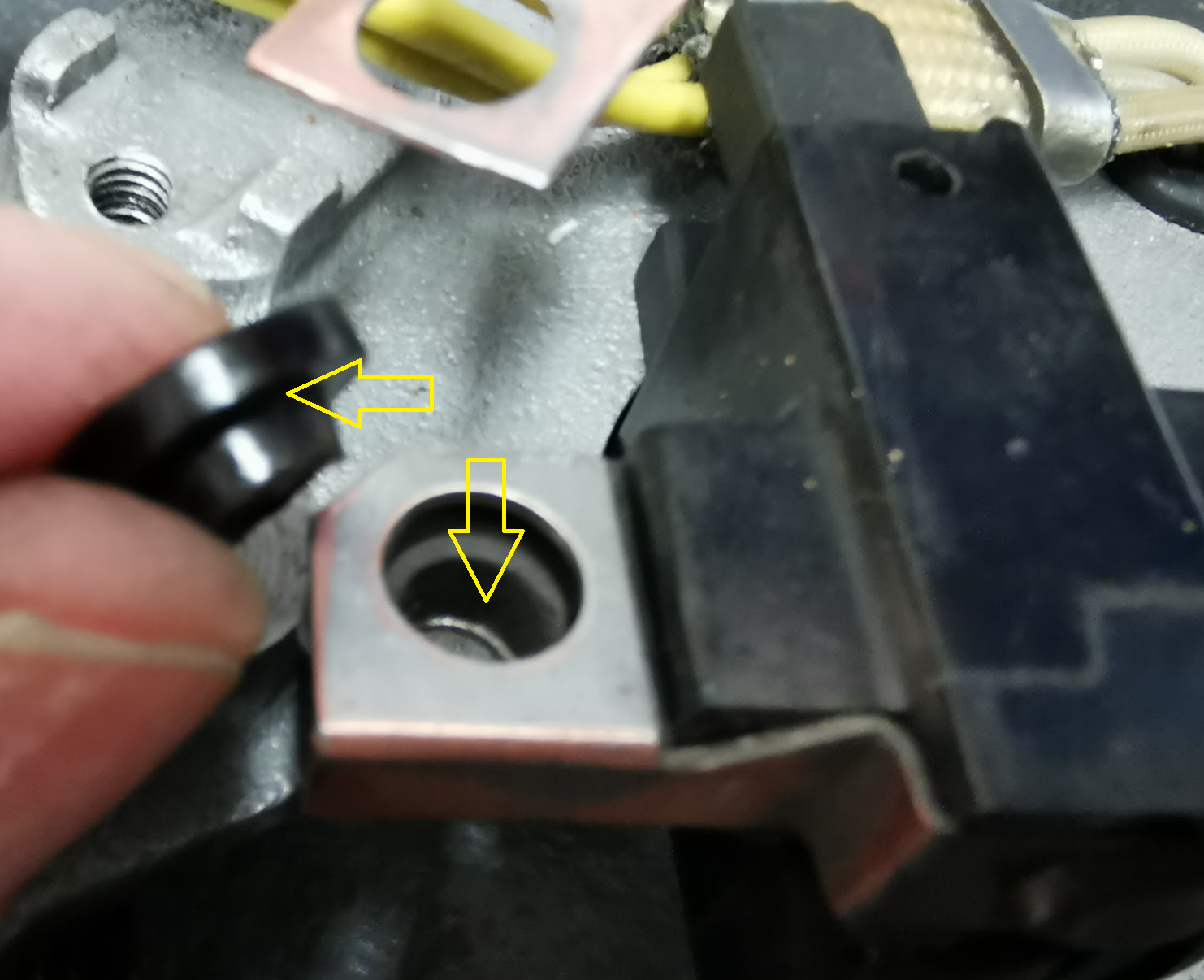
All the terminals were polished too. Don’t forget to mount the isolation cap when assembling the brushes. If not you will short the positive pole down to ground.

The old sleeve was brittle and had to be replaced. I went for a more modern flexible type and wrapped around a textile type of tape able to withstand 150 deg C.
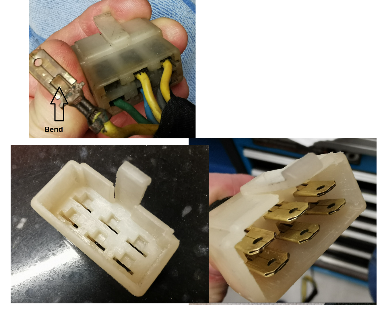
Bend down the locking lip of the terminal and pull out from the rear side. I did a lot of tips and tricks from YouTube how to remove the yellowing of the plastic. Used both ultrasonic cleaner and hydrogen peroxide + UV light. Not perfect, but it became better. Polished the terminals and mounted it all back in place.
Soldering:

You can replace all the wires, but I didn’t. Some of the wires were extended to make a proper wiring harness with correct lenght on all the wires. To make the soldering more easy I wrap a single wire around the wires to keep them both in place during the soldering. Added a double set of heat shrink tubings.
Mounted on the bike:

Measurements:
Stator windings:
| Bike | L1-L2 | L1-L3 | L2-L3 |
| GT750 | 0,7 ohm | 0,7 ohm | 0,7 ohm |
| GT380 | 0,7 ohm | 0,7 ohm | 0,7 ohm |
Rotor windings:
| Bike | Between green and black/white wire on GT380 and between green and ground (frame) on GT750 |
| GT750 | 5,8 ohm |
| GT380 | 6,8 ohm |
On the stator windings all measurements are done between the phases, the yellow wires.
Please notice the connectors. On the GT380 there is 6 pins and only 4 pins on the GT750. The ground (black/ white wire) and neutral indicator (blue wire) is missing. To measure the rotor on GT750 you therfore have to measure from the green wire to any GND points on the frame.
Note! If you measure rotor through the connector you will also measure through the brushes. If you get a very hight value you have bad connections in the brushes due to dirt and oxidation. Apply 12V DC for some seconds into the rotor and it will be all OK.
Numbers from the service manual:
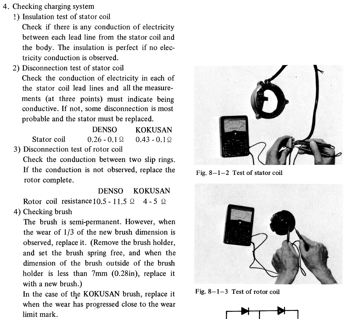
I find those numbers hard to belive, can’t be right. The stator coil (windings) can’t vary from 0,26 ohm down to 0,1 and be valid.
Stator windings: The resistance in the stator windings don’t change over time. It’s not magic, it’s a wire winded around a some iron core and the length and thickness of the wire will define the resistance. If you get a short between some of the wires the resistance will go down and not increase. And you will see a difference between the three phases. You will never have three identical fault in the same stator. The measurements I did gave higher resistance and were identical on both the GT380 and the GT750.
Rotor windings:
The rotor resistance I measured on both GT750 and GT380 is much lower compare to the manual. OK, one reason can be a short between windings in the rotor. But i checked all 12 magnets and verified they all had the correct Norh and South poles with the same strenght. A short giving half the resitance compare to the number in the manual would give weak magnetic field on some of the magnets. Since I have about the same measuremetns on both rotors and the GT750 is running fine and gives the correct voltage to the battery I’m pretty sure it’s all OK. Why the numbers in the manual are so differnt, I really don’t know.