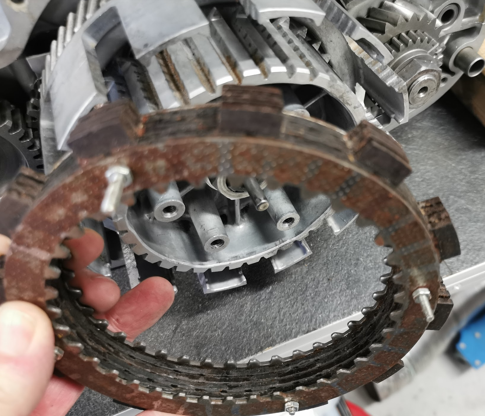
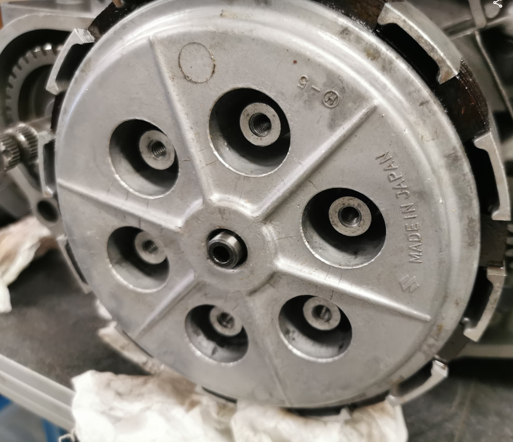
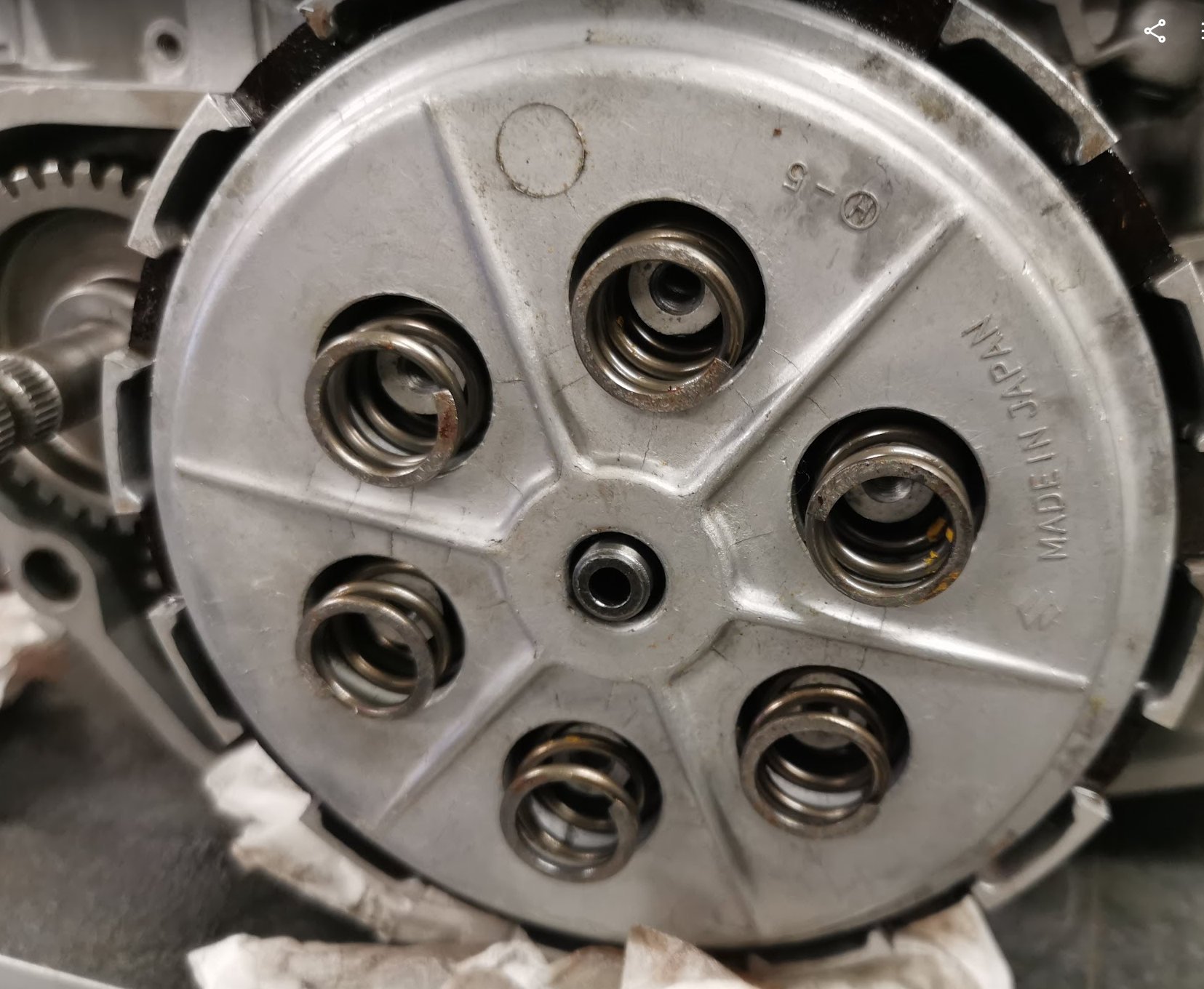
See the service manual for the procedure how to hook up the clutch cable and do the adjustments. I will also update this post later on when I do my own clutch adjustments.
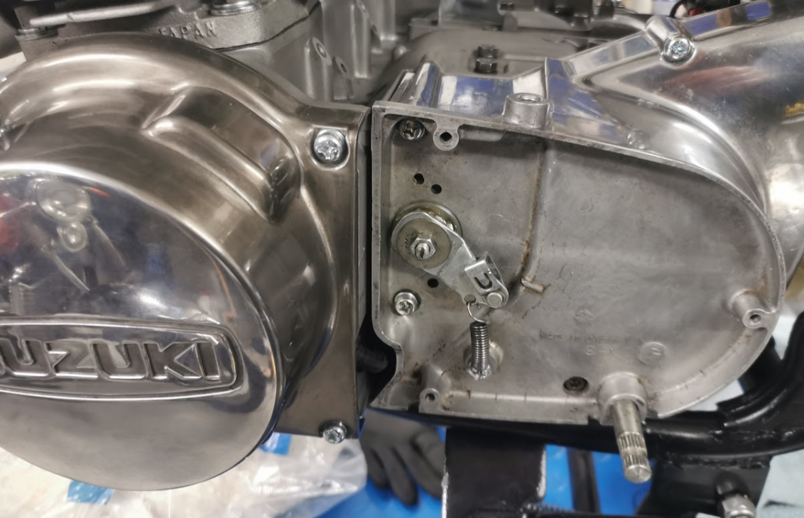
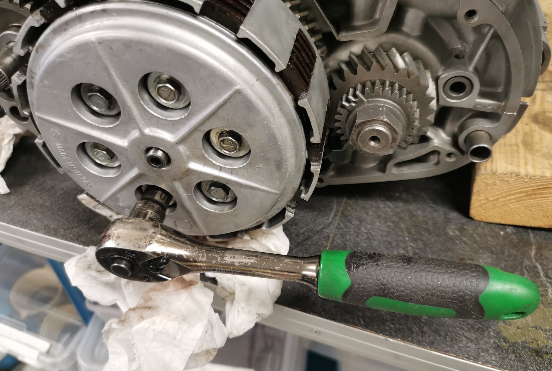
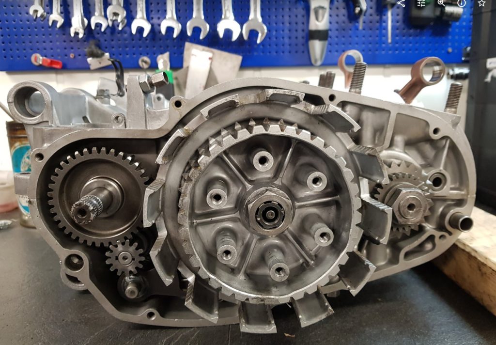
This is a trial assembly of the side cover, just to see if it all fits. The covers on top of the engine are also loose. Will be removed before I load the engine into the frame. The crank lock nut has to be tighten after the engine is bolted into the frame. I should have tighten the nut before the cylinders were mounted and blocked the rods when doing so, but now it’s to late. Will therefore lock the front sprocket when tightening the nut. Difficult to be done before the engine is bolted in the frame.
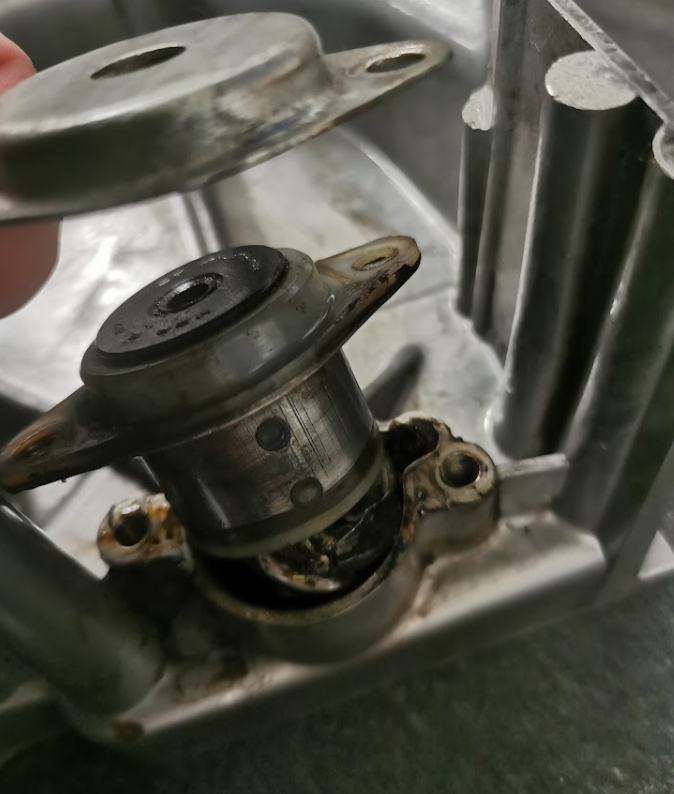
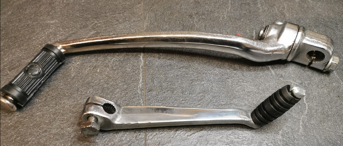
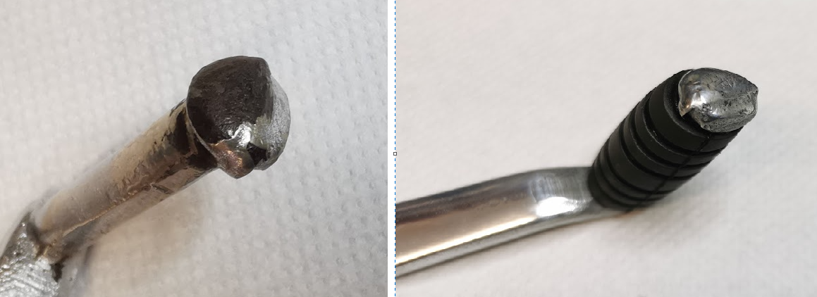
Two more parts done today with new rubber mounted. The kick starter and the gear shifter.
The kick starter was only cleaned and polished + new rubber mounted.
The gear shifter had some bad parts of chrome coming off. I did a gentle sandblasting of the ugly parts and nickel plated the entire shifter without removing the old chrome. Came out pretty good I think.
I didn’t do anything with the odd looking edge of the gear shifter. This is how it was made from the factory 50 years ago.
Phuu, a lot of work, dirty work as well. Dust all over my face.
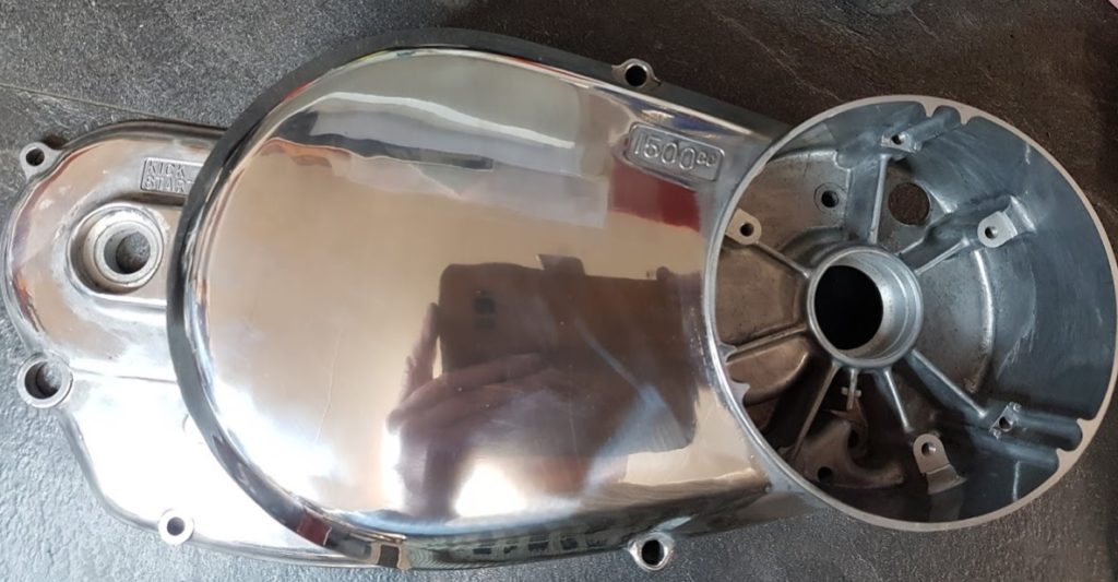
I have three engine covers to choose from. Two of them have some very bad scratches, too bad to ever look good again. Got hold of an unused one, the new type with 1500cc oil level label.
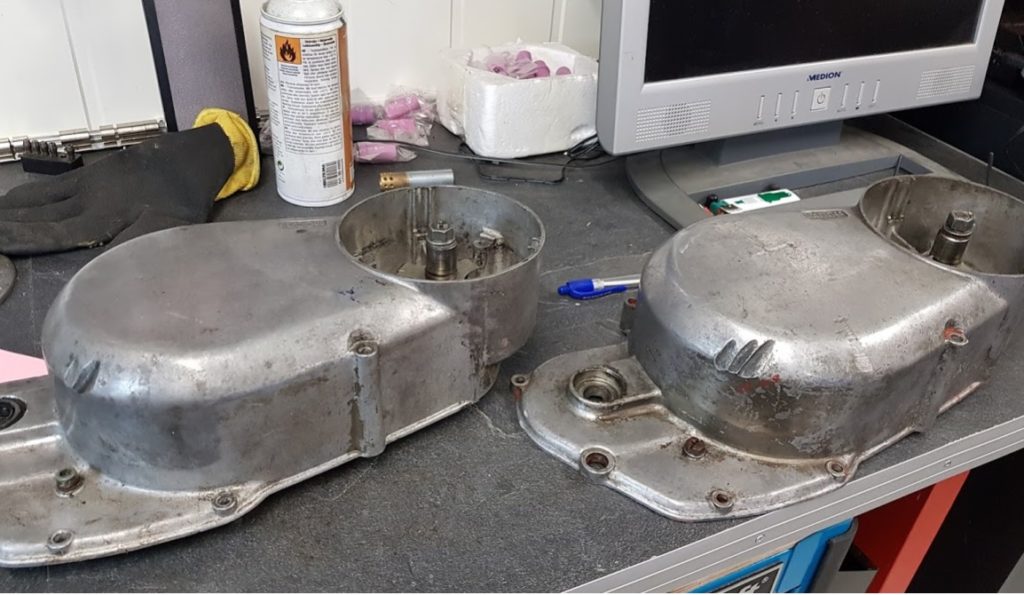
The bad ones:
Parts for the timing will be removed and reused in the new cover. One of them has a very good nylon gear for the timing assembly.
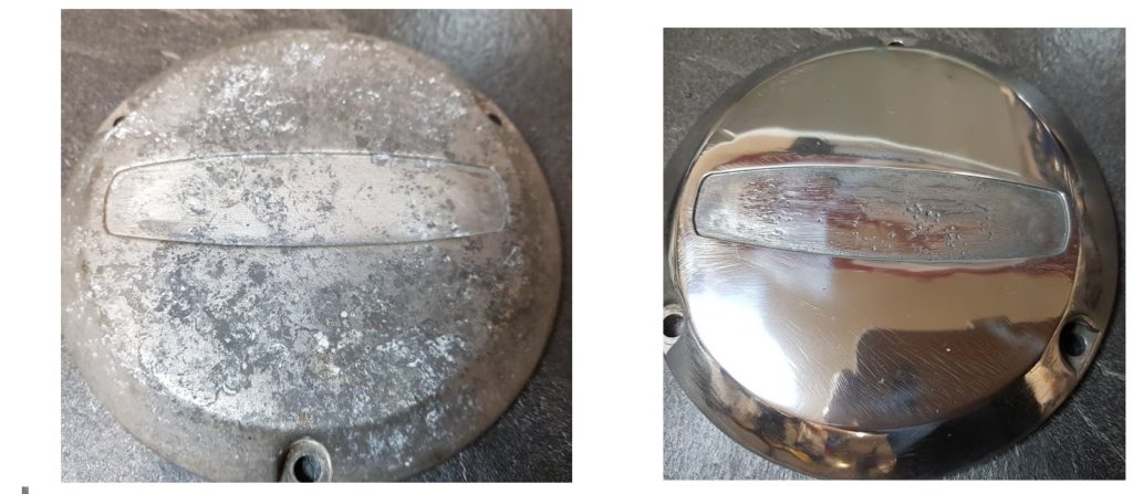
Timing cover:
Before and after one hour of grinding and polishing. Had to grind off a lot of material to remove some deep dents and scratches. Still some scratches left but the cover will be replaced later on with a J cover with engraved Suzuki logo. This is a later model with a sticker in the middle.
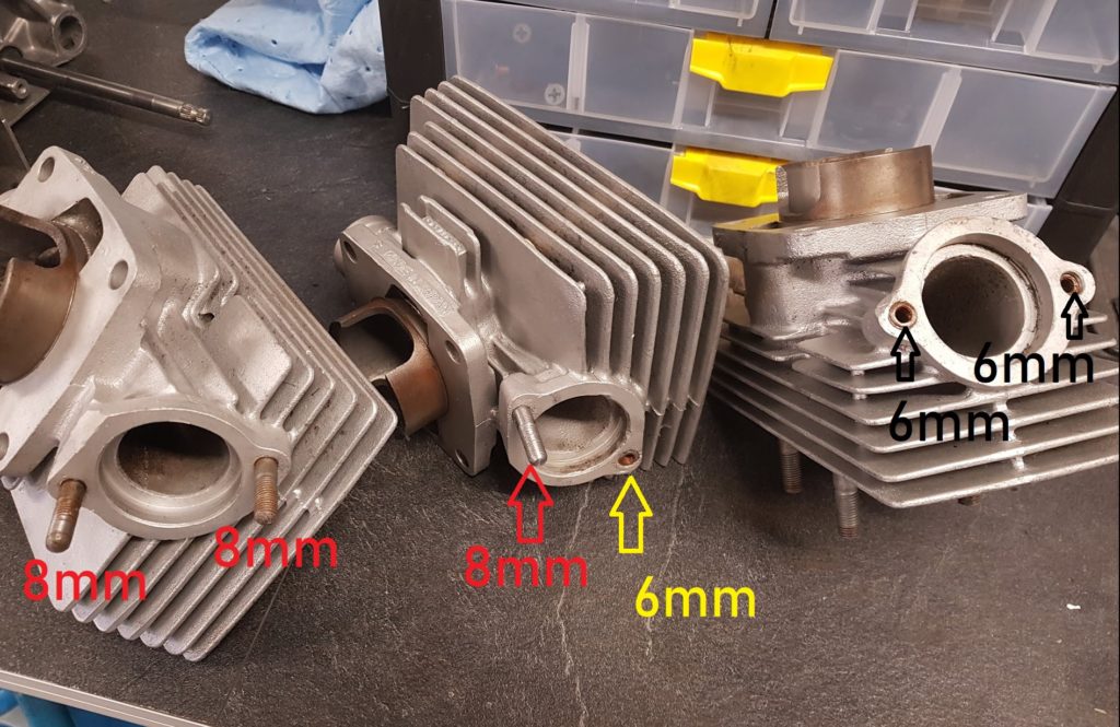
Got a surprise when starting to assemble the cylinders. Some of the 8mm stud bolts where missing and had been replaced with 6mm bolts.
This is what happens when working on a 48 years old project. Previous owners must have been too careless while mounting the pipes, as usually, too much torque and the threads are gone. A bit odd fix. They have used 6mm insterts in three places. I can’t have a mix of 8mm stud bolts and 6mm bolts. Not on a bike as stunning as this 🙂 So, what to do ?
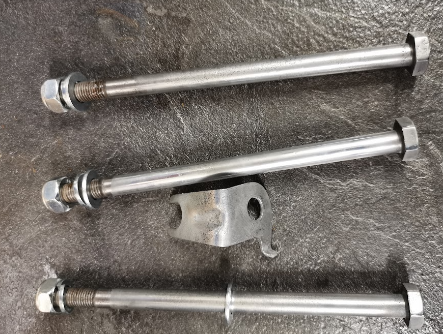
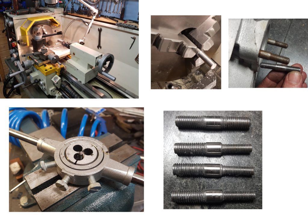
Having a lathe is a big advantage while doing overhaul on a bike, a worn out bike.
Made four new studs. One original with 8mm threads in both ends and three with 8 and 6mm. One of the 6mm came out a bit bent, will fix it.
Done ! 🙂
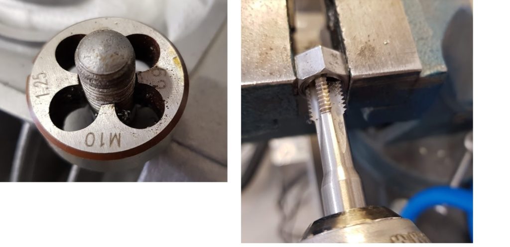
Threads:
I did a refresh of the threads on both the bolts and the nuts. Not to get a surprise during the mounting.
10mmx1,25mm fine pitch threads.
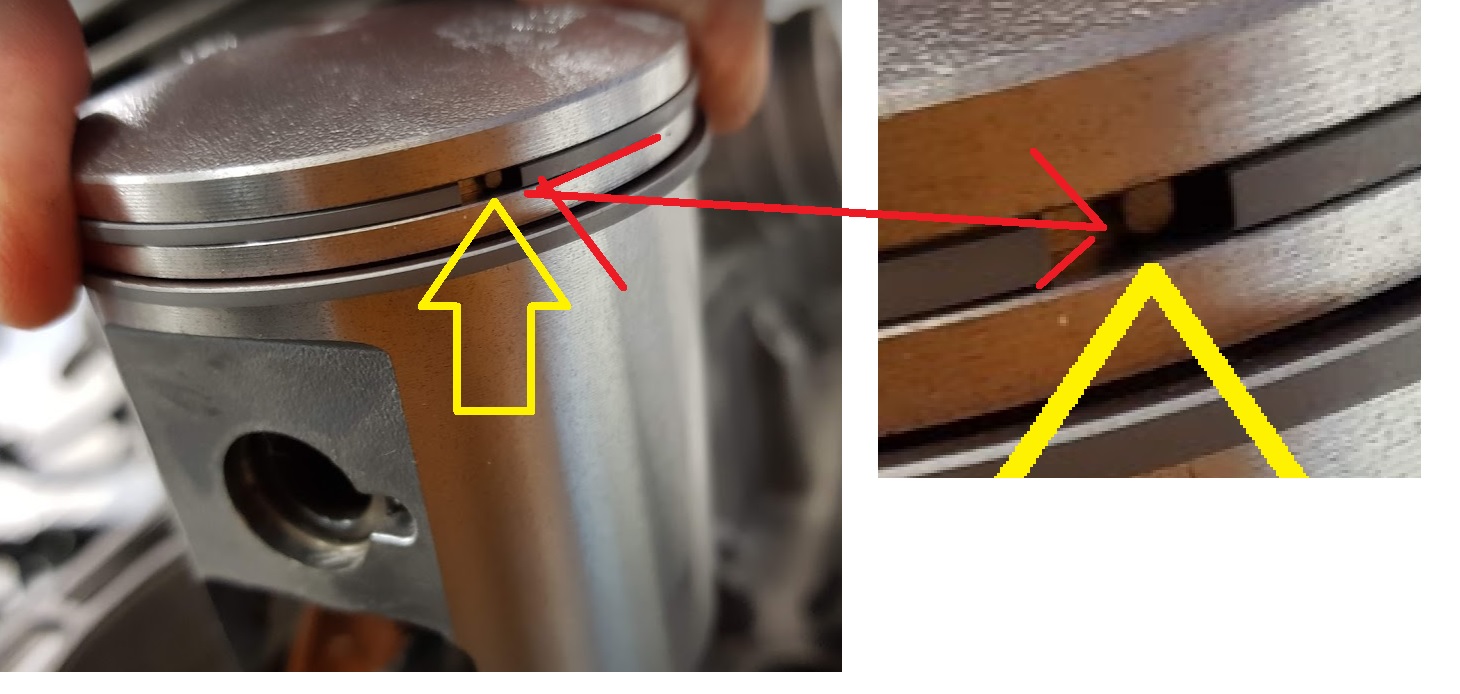
Piston rings:
Before mounting the cylinder, make sure the gap in the piston ring is above the pin located in the groove.
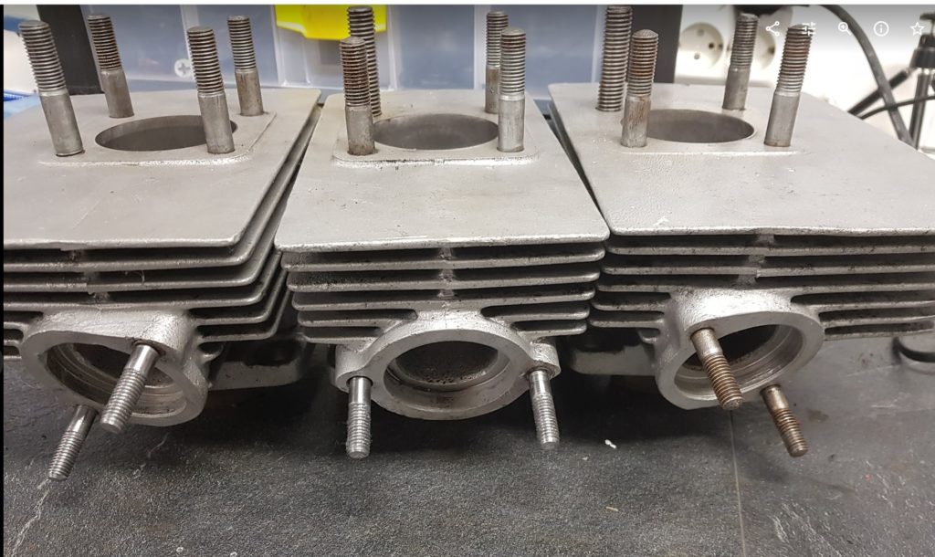
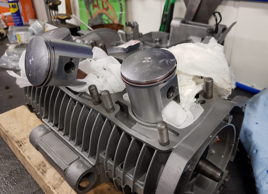
Mounting of the cylinders:
Mount the gaskets and start with the cylinder in the middle. Apply some 2-stroke oil and slide the cylinder down. Don’t forget about the position of the piston ring to close above the little pin. Should slide easy down, not needed to use any force.
The last one and it’s done.
I was not able to find any torque settings for the cylindres, only for the cylinder head. Since there is no space to use torque wrench on the nuts I used the tools I had and fasten using sensible amount of torque 🙂
SRIS:
All of the cylinders have plugged SRIS outlets. I will therefore mount the case without the SRIS valve no.17. Dont’ see any issues of burning a bit more smoke at startup.
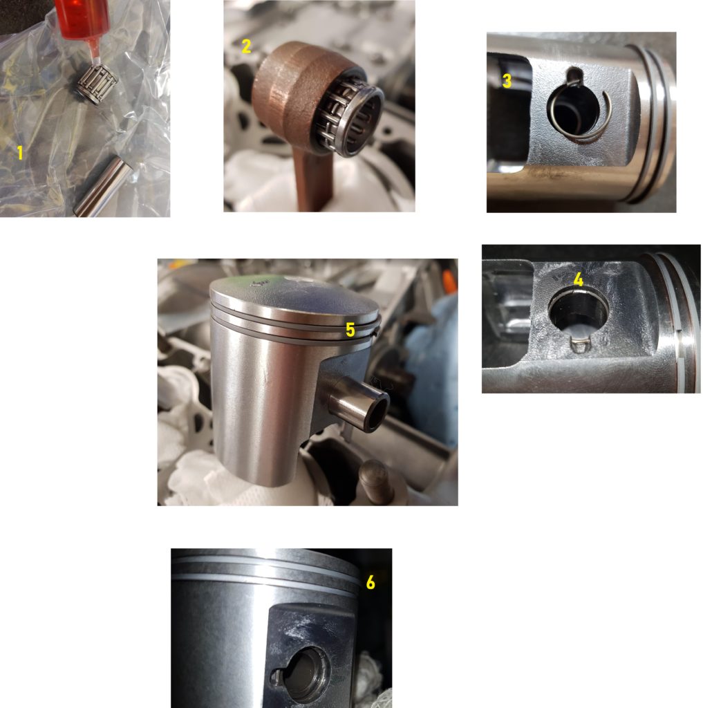
Please we aware of some differences:For the GT 380 all three pistons are identical. There are no washer in the piston as on the latest GT750 models, only the circlip to keep the pin in position.
Pictures from the GT380:
Remember to move the circlip gap at the opposite position to the groove, picture 3-4.
Insert the last circlip and you are done (picture 6 )
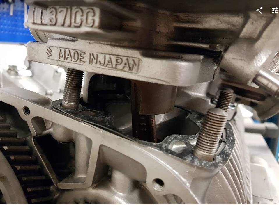
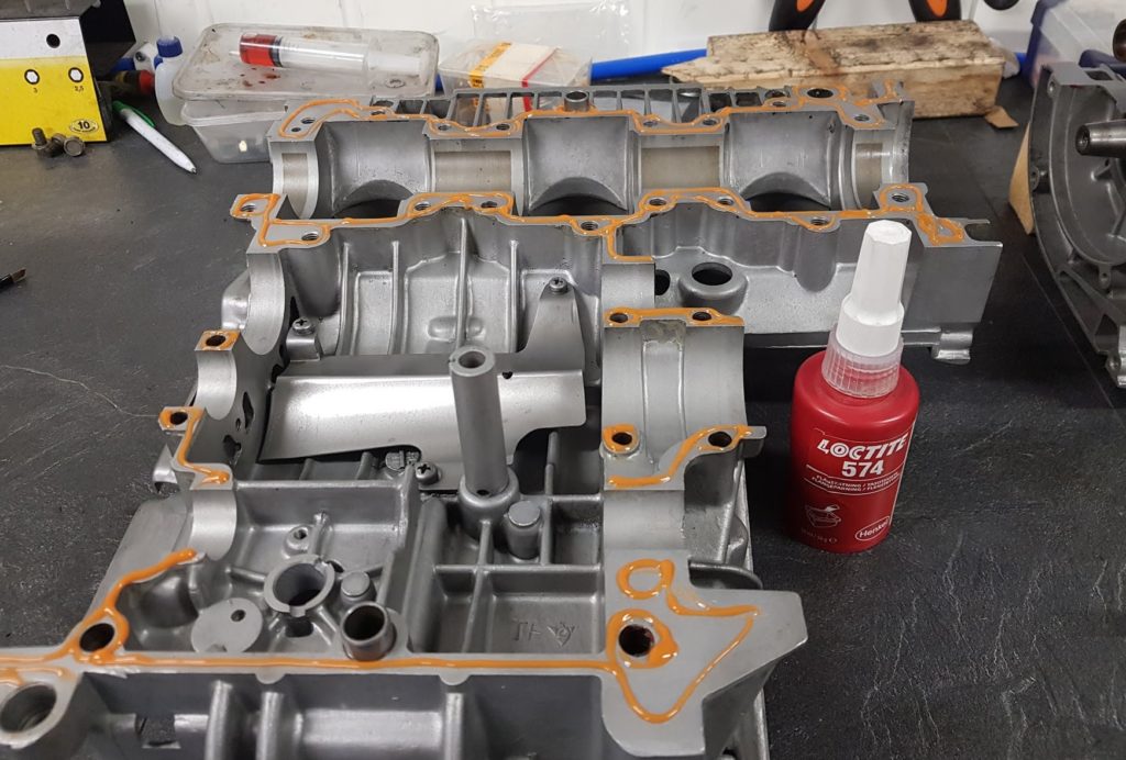
The upper part of the crankcase was glued using Loctite 574 as sealing. In the same way as I did on my GT750.
The Loctite 574 does not harden in air, only under pressure. A very common type of sealing for all type of crankcase.
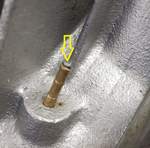
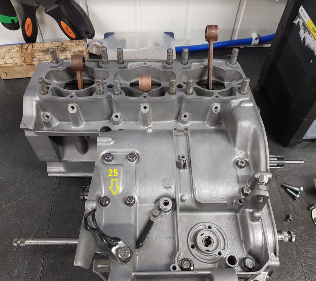
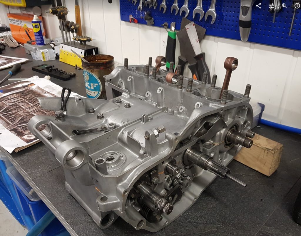
Closing the crankcase:
All bolts are labeled with numbers. If you look close at the image you will see the number 25 is written into the case, just below the yellow arrow. That’s the order of the torque settings. If the crankcase is clean it’s easy to see the numbers. Mount all the bolt on the top side but don’t thight too much at this point. Make sure the crank is moving freely before turning the case onto the other side.
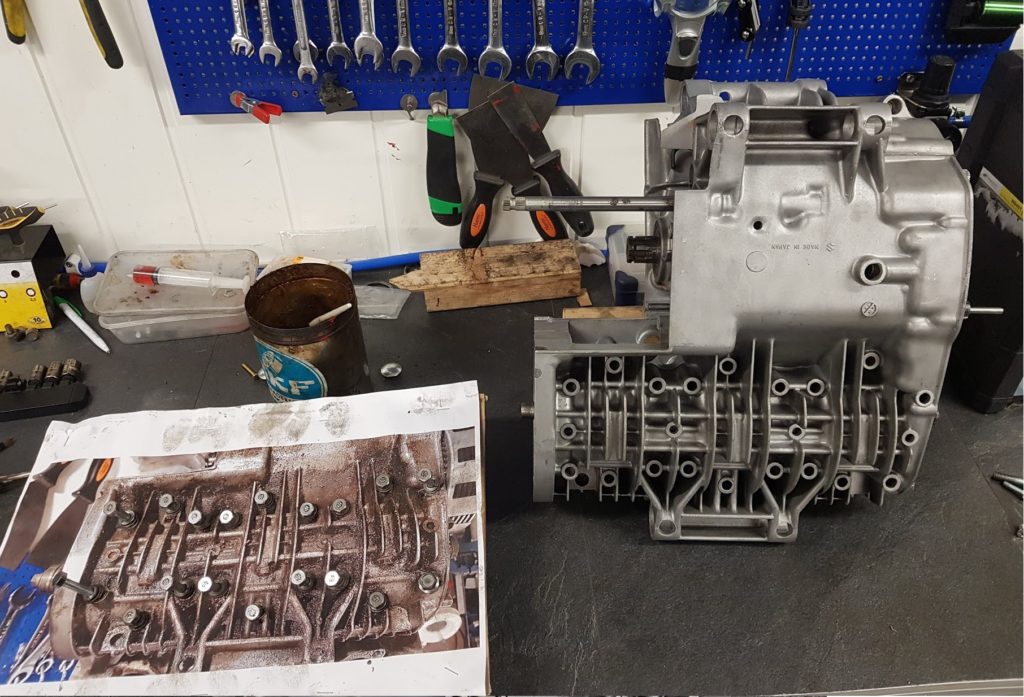
Since I have stored the bolts on a picture glued to a carton It’s easy to pick the right bolts with the correct length. All of them have been cleaned and polished. The S mark indicate bolts with more strenghts than bolts without the lable. The S bolts are for GT models but not for GS models. The GS bikes have labels with 7 on, not S. I found only GS bolts mounted on a spare crankase from a late GT model, 76-77. Not sure if that was original from the Suzuki factory or if someone had swapped them all. On my GT380 engine I mounted all the S-bolts I had except from a couple of 7-bolts.
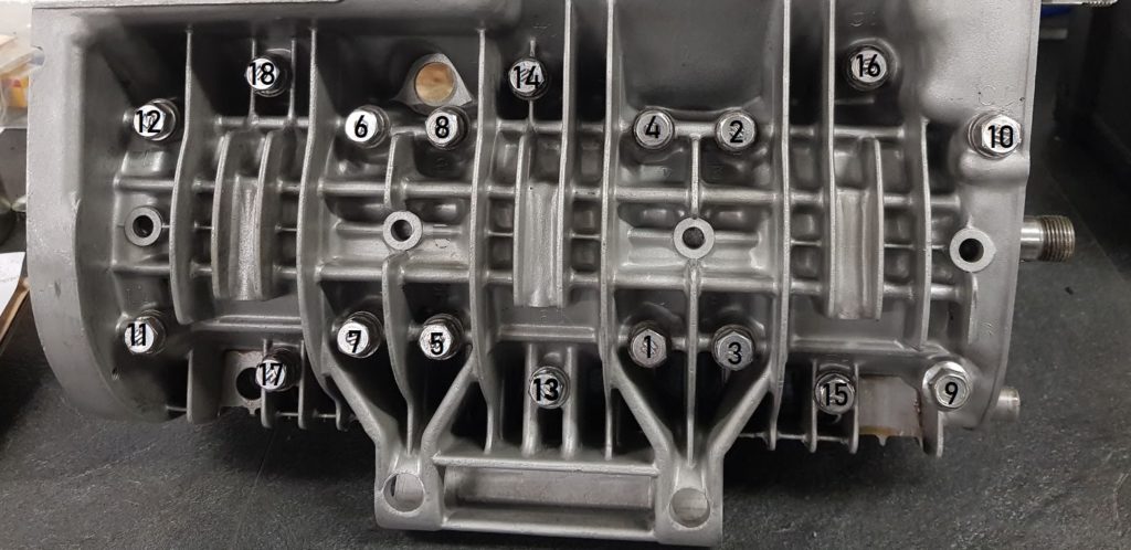
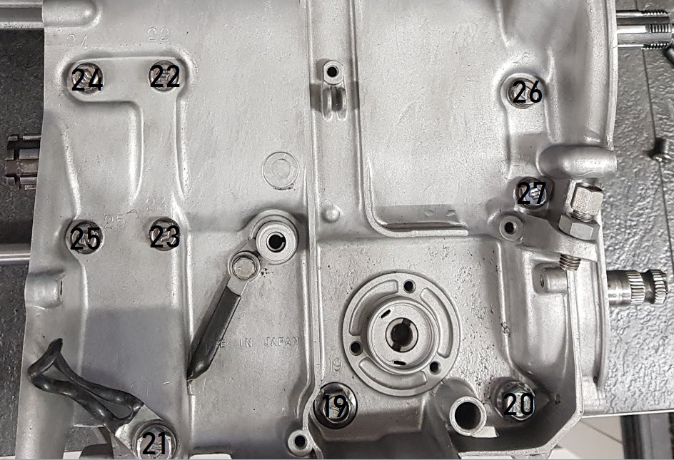
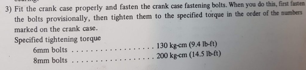
Torque order:
Bottom case:
In addition to my picture above you will find the torque order in the manual and it’s written onto the case.