Rear footrest

I bought new rubber for the footrest. The metal parts were sand blasted, sanded and nickel platet.

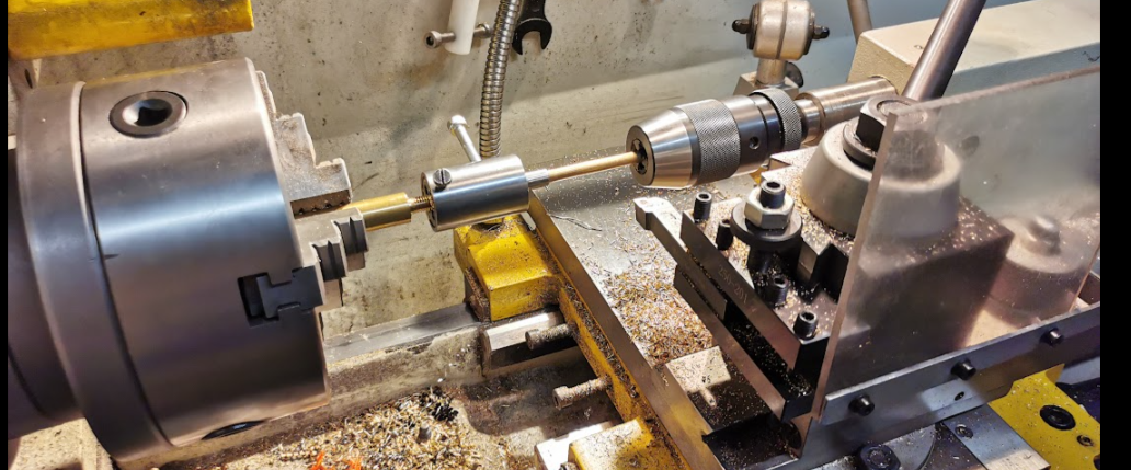
The lock pins were missing but I made new ones from brass using my lathe and they were nickel plated.

Mounted on the bike.
I bought new rubber for the footrest. The metal parts were sand blasted, sanded and nickel platet.
The lock pins were missing but I made new ones from brass using my lathe and they were nickel plated.
Mounted on the bike.

The early models have three outputs from the fuel tap to each carburetor. The later models have one output to a rack mounted manifoil distributing the fuel to the carbs.
There are three fuel filters. One for the main tank and one for the reserve tank. The last one is in the bottom and can easily be maintained and cleaned.
How to test the function:
The valve in the tap is vacuum driven. Here is a simple test setup to verify its function:

I’m using a syringe to make the vacuum for opening the valve. I let the denatured alcohol stay in the upper syringe over night to be sure there were no leakage at the ON postion. When moving the lower syringe the vacuume open the valve and it all works fine. Please watch the video:
If the fuel tap is not working you can strip it down, clean and replace parts (if you can find a new part).
I swapped some parts from the later model, but most parts are different. I was only able to swap the bottom filter + the gasket.
The bottom filter:

Looks like the filters are the same on all models.
Petrol tap switch:

The gasket behind the cover is different on J-K models compared to later models. Don’t waste money and buy the wrong one.

This is the correct type of gasket for the J-K model. The hole at the center is smaller on the early models + layout of the channels are a bit different too. You can’t swap the gaskets from later to old models.

If you have a leakage, the tension of this spring located under the cover can be the issue. If the movement of the arm feels to loose, bend the spring a bit to make a better tension to the gasket.
How it all works:

ON postion:
Main tank will flow to the vacuum valve (as the arrow on the picture in the middle show)
RES postion:
The RES will flow to the vacuum valve.
PRI postion:
The RES will flow to the PRI (direct to the carbs bypassing the vacuum valve)
Vacuum valve:

If you open the vacuum valve, be sure to assemble correct. The hole in the diaphragm have to fit to the gasket and hole shown in the picture above.
Replace the o-ring in the valve if needed.

Was lucky to get hold of the real thing. Genuine Suzuki mirror with the S-mark.
The threads were wrong, 10mm, but should be 8mm. I made adapters in brass using my lathe, and thereafter they were nickel plated and mounted on the bike.
8mm outside and 10mm ( fine pitch) internally.

8mm

Nickel plated, still using my 13 years old nickel bath.


Time to start the overhaul of the carbs. The first time I’m doing this, so it has to be learning by doing + take a lot of photos and watch YouTube.
Sorting out the cables and carbs:

L, M and R :

This carburetor is the 33011 type. The last letter will be L, M og R for Left, Middle and Right.
Remember to organize all parts in boxes and don’t mix between L,M and R.
Removing the throttle valve:

Uncrew the top and slide off.
Removing the throttle cable and return spring:

Remove the throttle cable from the valve.
Return spring:

Remove the return spring.
Removing the choke ( starter piston):

Remove and inspect the starter valve (choke)

Remove the Drain plug and the inspection bolt for the throttle valve.
Removing the float, float valve and seat:

Inspect the valve for any worn.
Removing jets:

Needle jet:

Insert a screw and give it a tap with a hammer to get loose. Remove from the other side.
Note: The needle jet is also named Needle nozzle in the manual.
Ultrasonic cleaning:
Wather blasting:
After the ultrasonic cleaning I got all the alu parts wather blasted, looks very nice 🙂

Next step will be the assembling process, but not today.
Assembling:

All channels were well air blasted, cleaned with solvent, and air blasted again.
Mounting the needle jet (Needle nozzle):

I made a tool in brass for a more easy way to insert the needle jet. Please be aware of the lock pin and the orientation of the needle jet. Insert the jet from the other side and give tap the tool gently if needed.
Mounting the Main Jet:

Use correct size (with) of the washer. If it’s too narrow, the Needle nozzle can slide out. As shown in the picture above the Main jet will also lock the Needle nozzle in place.
Hard to see how it can slide through on the other side, working against gravity, but can happen during the assembling process it the carburetor is turned upside down. But as mentioned above, the main jet will lock it all in place if the spacer has the correct diameter.
The standard Main jet size is 0,8mm, marked as 80.
Mounting the pilot jet:

#22,5 size according to the manual.
Mounting the Air Jet:

Turn the Air jet all the way in, than 1,5 turn backwards.
Note: The picture is from the left carburetor. For the M and R, the jet is fitted from the other side.
Mounting the Idle Jet:

Did some cleaning and polishing before mounting.
Gasket:

I used the old gasket as a template, drew the outline and cut a new one in 1mm gasket material. Seems to fit quite well.
Float:

Warm the water almost to the boiling point and dip the float into the hot water.
To check the float for leakages ( it’s 50 years old and fragile) put in hot water and look for bubbles. Locate the hole and clean well before soldering.

This is not easy to fix. Clamp the part gently so it doesn’t fell apart due to the pressure inside when heating up.
Mounting the Float Seat and valve:

You can use the old one if it’s not worn.
Mounting the Float and Float Pin:

The float height will be adjusted later on when I have all three carbs ready.
Almost done:

A simple test to see how it all fit together. I think I have learned a bit so far. Hopefully the images can be at help for other as well. At least for me, when I’m doing the M and R carburetors. But not tonight.
Drain plug and inspection screw:

Float height :

Adjusting the fuel level according to the service manual.
Needle jet height:

The circlip at the needle jet for the center carburetor should be in the middle position. For the right and left carb, mount the circlip in the second groove from the top. This will give a bit more fuel to the center cylinder.
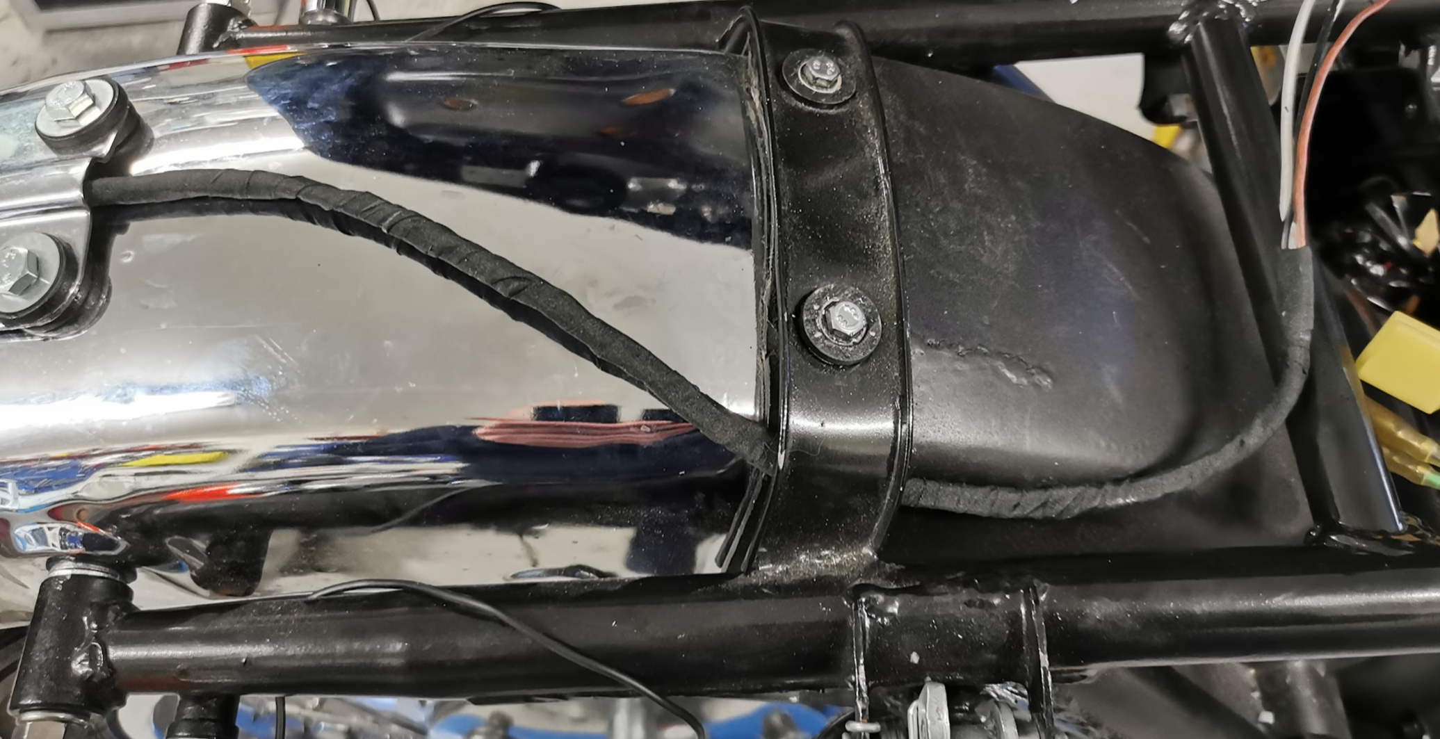
Rubber hose:

Replace the rubber hose if it’s old and hardened. I got them all new and the yellow arrow shows the directions for mounting the rubber hose.
Mounted on the bike:

Before routing the throttle and choke cables I mounted them all on the bike. Will buy new clamps for the rubber hoses so it all looks nice shiny.
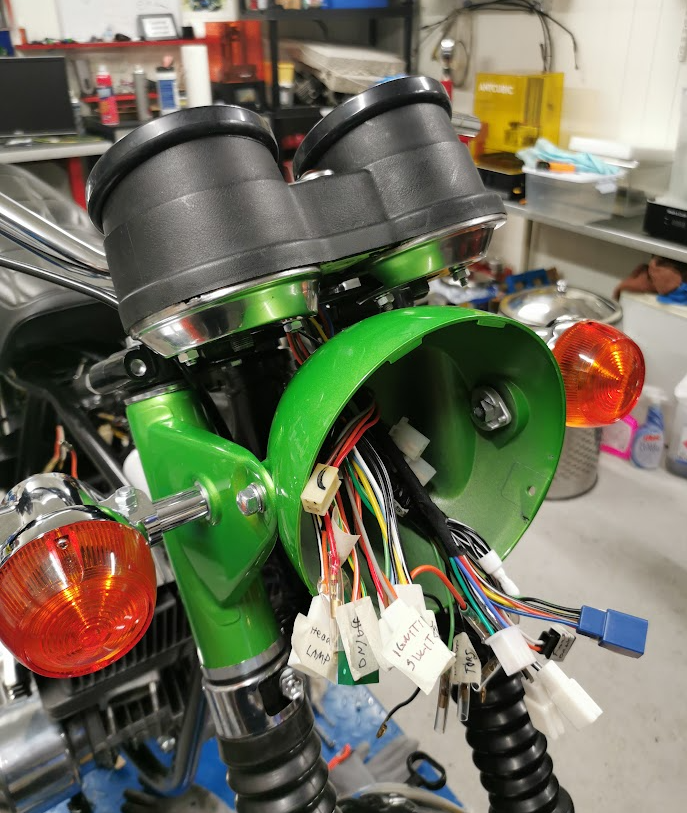
Ground (GND) to the lamps:

For the rear lamps the GND is not any issue. The indicators are mounted direct into the frame.
For the front indicators it’s more difficult. On my GT750A model the head light house is all metal and clamp GND direct to the headlamp bracket. On my GT380J it’s different. To make a proper grounding I solder wires to copper spacers and they were both connected to the GND wires inside the head light.
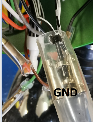
Wires from the spacers connected to GND.

Green wire (right indicator lamp) Black wire ( left indicator lamp)

All indicators worked fine, + the instrument lamp as well 🙂
Looks like all of the electronics are working fine without any smoke 🙂
Making wires for the tail and brake lamp:

White wire: Brake
Brown wire: Tail
Black / white : GND

Wrapping the wires using textile tape.
Cable layout:
Decided to lay down the cable as shown in the picture.
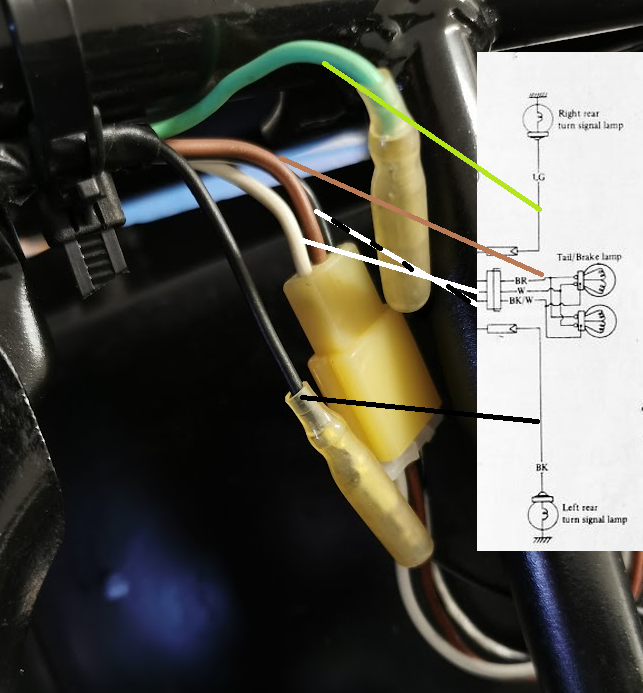
Tail, brake + left and right turn signal.

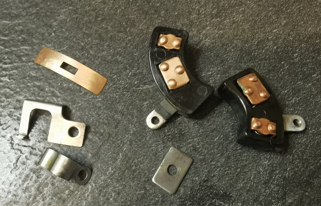
This is what I had. Two right hand switches (one old and one new ) + one old left hand side switch.
Decided to mount the new one and restore the right hand side switch.

The overhaul process:

Important step: Take a pictures before disassembling the parts. Note, the clip shown by the arrow is mounted the wrong way. In that position it will short the headlight high beam to GND.
Primer painting.

Black paint + text painting.

Cleaning and polishing all electrical parts:
Wires:

Lower part switch assembled:

Upper part switch assembled:

Almost done:

Mounted:

Done: Made a 9 pins connector to fit the wiring harness in the headlight.

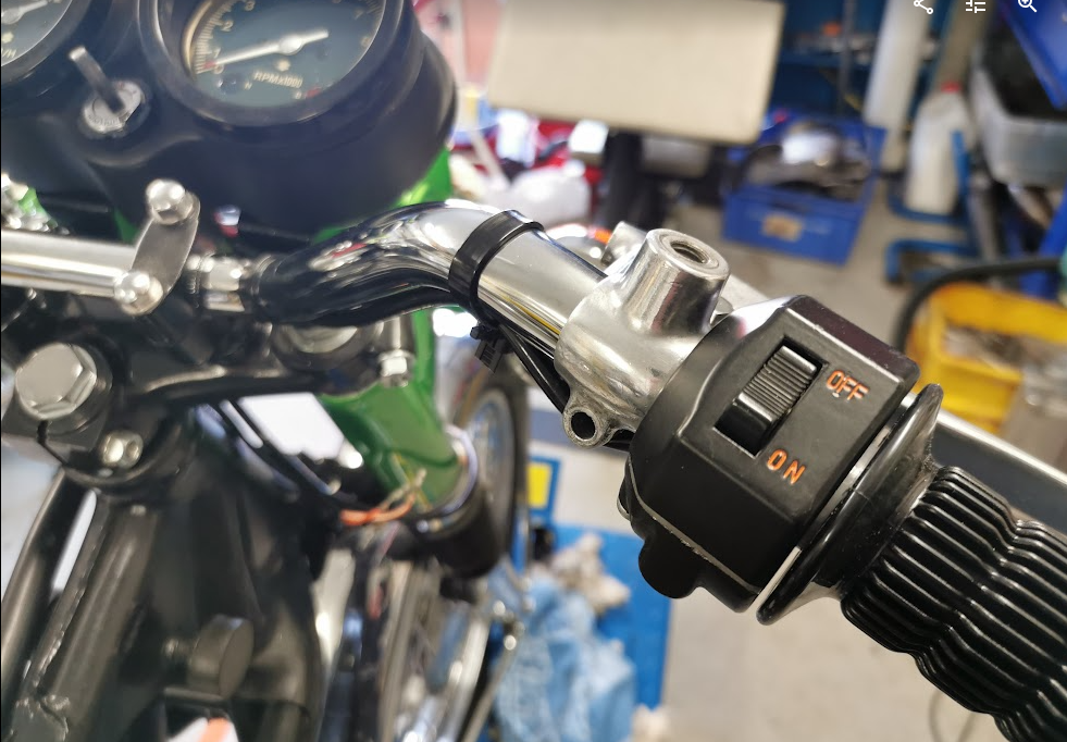
Right side switch:

Don’t even think about it, assembling the brake switch from below. The the spring will jump away along with rest of the small parts.
Turn the brake lever upside down. This is valid for GT750 as well.

I know, the nut and the bolt for the brake lever is wrong. Will be replaced later on when I get the parts. I have to use what I have to get going.

Make sure the switch moves freely to both positions.

Add the contact disk of the switch.

Mount the plastic enclosure and make sure you have a good strain relief.

Zip ties
I use reusable zip ties at this stage for an easy adjustments if needed.

This is what I had… not good at all.
On the J-model all wires are connected with individual connectors as shown in the diagram below.

On the wiring loom I bought brand new, it’s different. One blue 6-pins connector + two separate connectors for the speedometer lamp and the tachometer lamp.

Since I have all the tools to make the mating connectors I decided to make a new wiring loom for the lamps. The old one was anyhow in a bad shape, but what about the rubber sockets for the lamps?
Was able to buy metal part of the sockets and designed the rubber parts in two pieces, 3D printed them using rubber resin and mounted it all together.
The photos below shows the process:
3D printed rubber parts:

Connectors:


Old and new. Will use standard bulbs, not the LED type as shown in the picture.

Crimp tool:


The picture above shows the lamps with the correct color coding. I used a very soft multi strand wire, but was not able to find the black/ white type. You have to be true to the color coding so I painted a white stripe onto the black wire.
The wiring loom will be wrapped using a flexible textile tape. That gives a solid but flexible wiring loom, easy to be fitted.
Done:

STL files for 3D printing:

Time to start the assembly process, four years after it was taken apart. The following days and weeks will show if I miss something. Some parts have already been 3D printed new or bought new.
Starting with the bracket:

All the rubber parts where stripped off and I think all of them can be reused. The bracket got sandblasted and painted.

Remounted the greenhouse tent I used when painting the frame. Ready for new paintworks to be done.

First one layer of primer.

Then, two layers of paint.
The tent will soon be upgraded with ventilation since it will be used for bigger parts as well. An oven gave a nice temperature inside the tent.

Rubber parts mounted.
The paint finish could have been better. Perhaps I had to high temperature while spraying? I don’t care since this is a non visible part, covered by the clocks. Now it’s well protected against rust.

Inner parts were painted and glued to the mounting plate.

The rubber hose was made from an old rubber tube.

I made a test fit using the new 3D printed part and also cut a new glass …. but not sure.

Ended up using the old ones from 1972. They have some cracks but seems to fit well after all.

Mad a rubber seal from the old rubber tube and glued onto the cutout in the speedometer housing.
Note! Previous owner has made an ugly cut out to be able to fit the speedometer. That’s not needed if you mount the speedometer without the rear metal disk. Thereafter you mount the disk. But now it’s done I don’t care.


On this part I used textile tape instead of rubber.

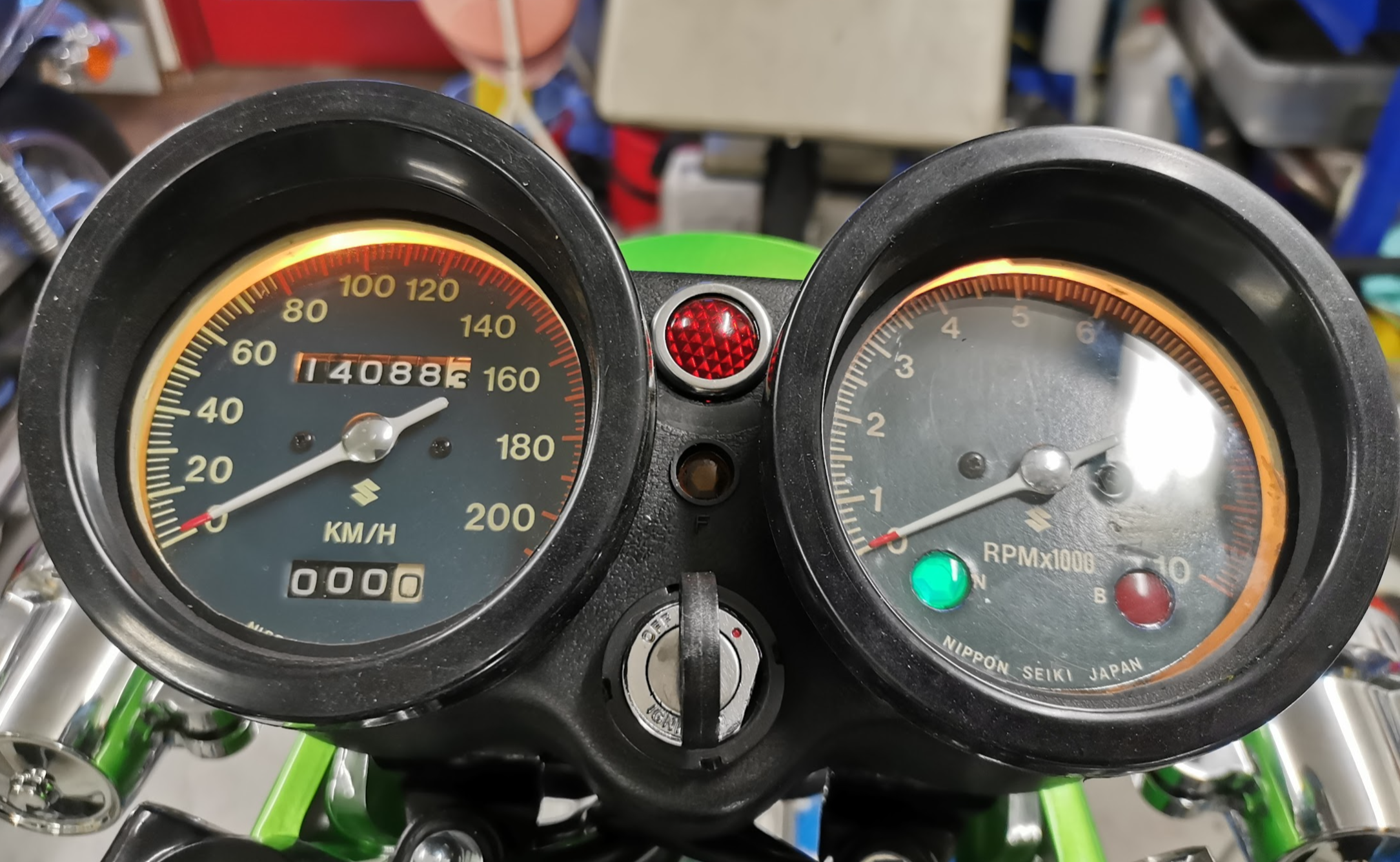
The clocks need to be glued to the inner housing. I prefitted to the bracket and made a mark to be sure it’s all aligned before gluing.

Glued and all the lamps are mounted ( and tested)

The upper rubber covers are quite loose and will be glued before I get the bike on the road.
the red lamp in the middle was meant to give a signal above 80km/h and is not in use. I will use it as an indicator to alarm if I forget the retrack the side stand.