Coolant
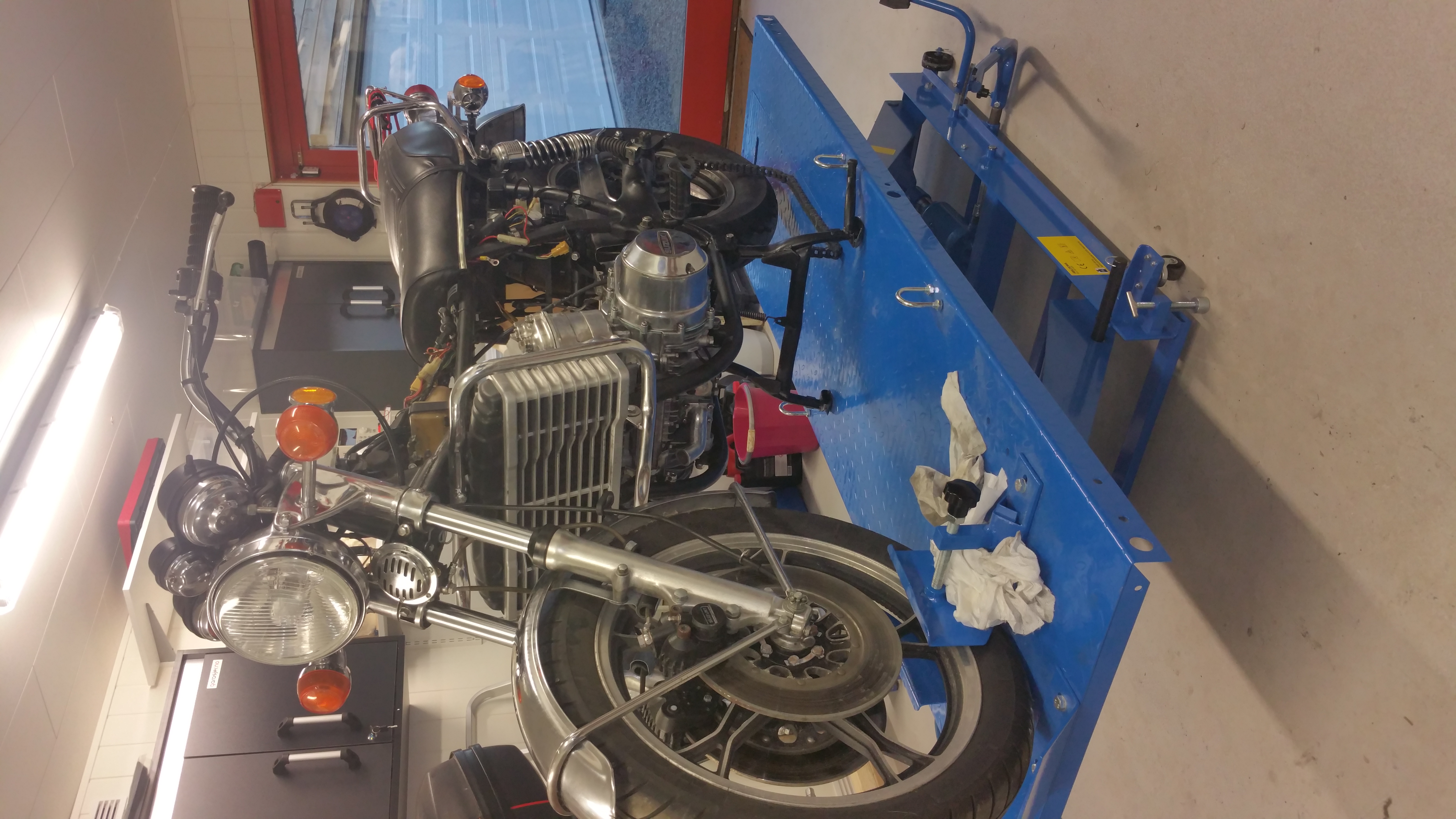
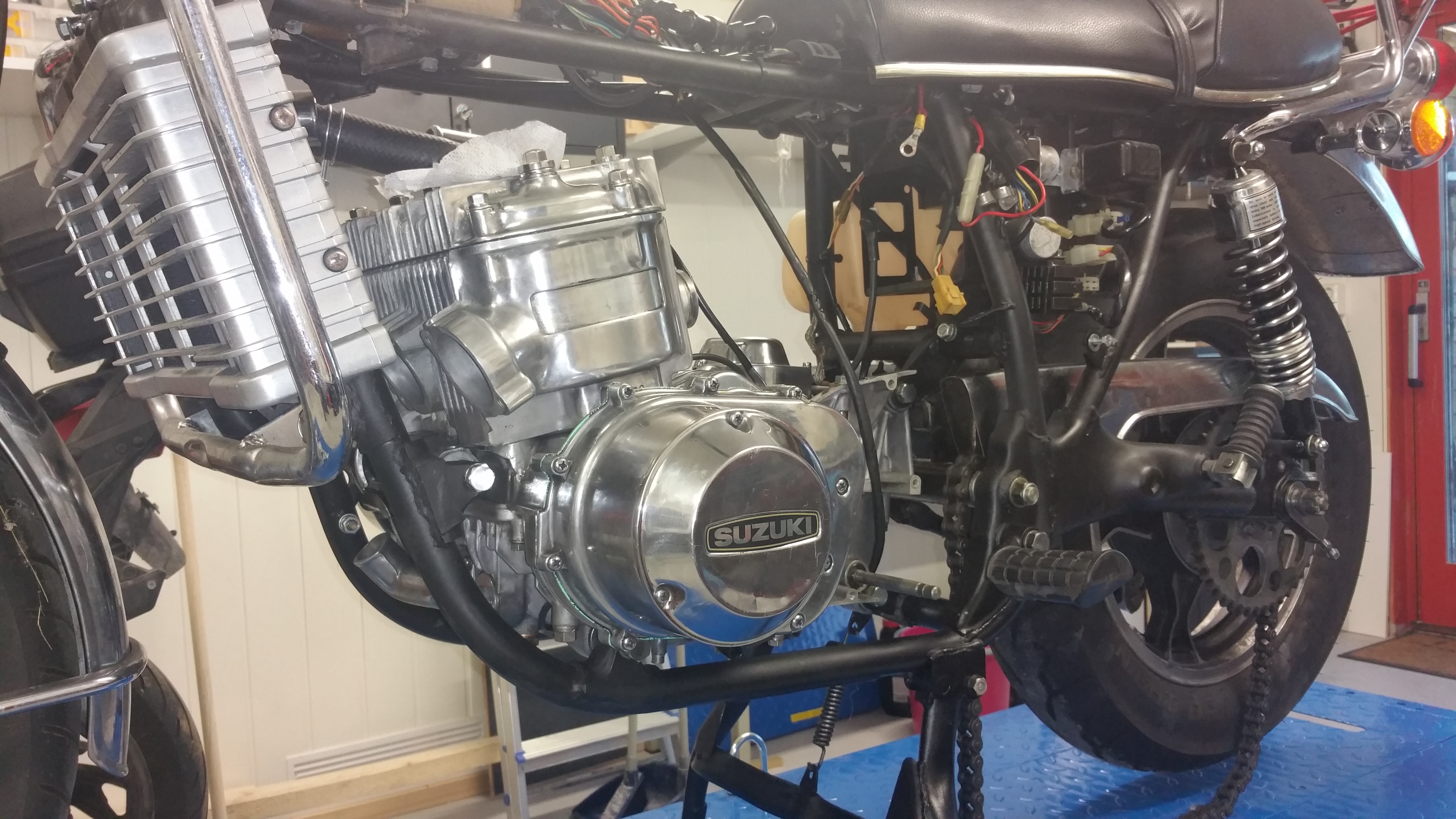
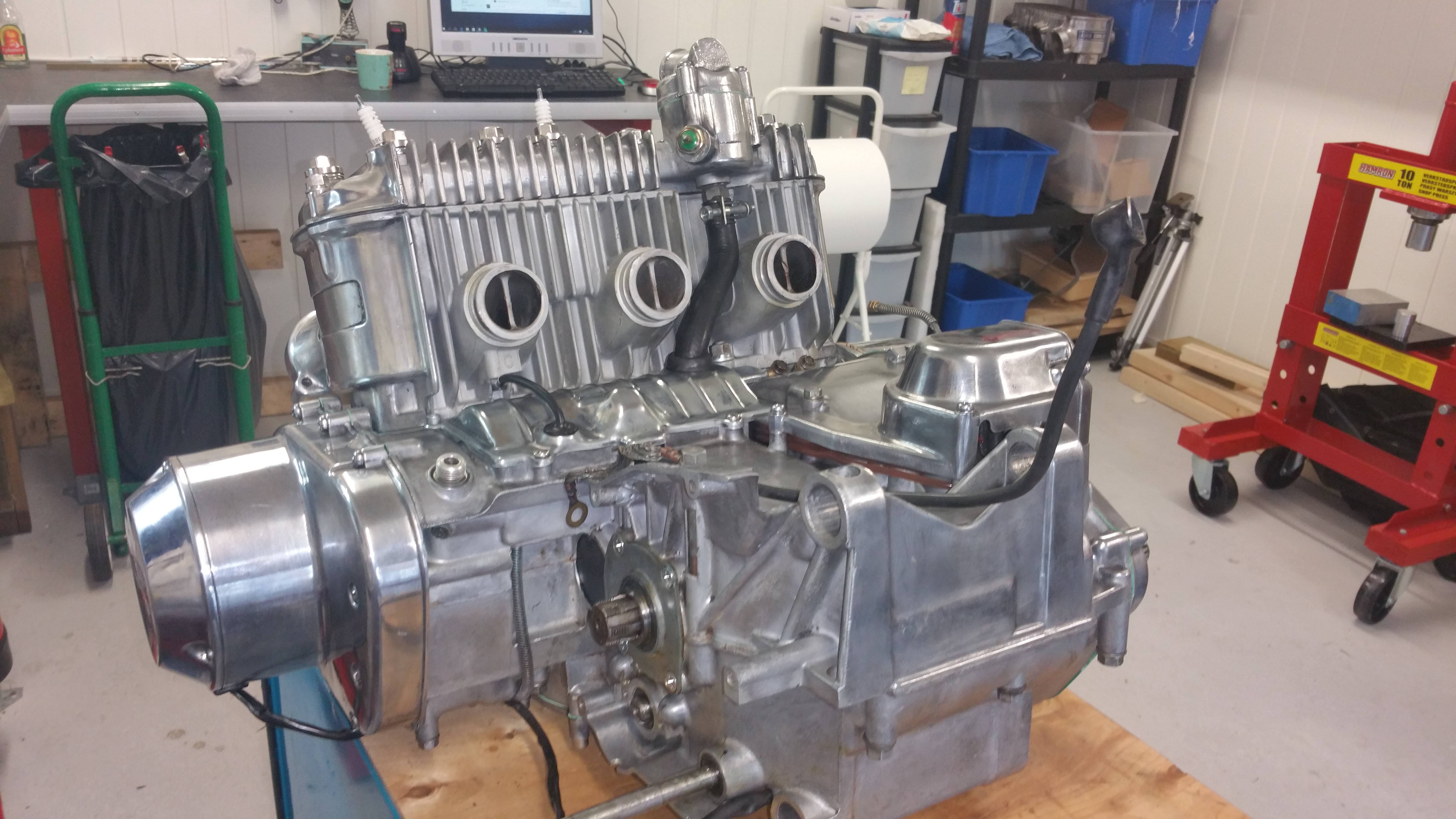
When I did the first restaurtion of the bike the engine was not opened. It was running fine exept from some loss in power from time to time. I thought it was an issue with the carburetors / fuel system. Later on I understood it was related to the sealings in the crankshaft. Had to start all over again, the engine out of the frame and get going with the overhaul of the engine.
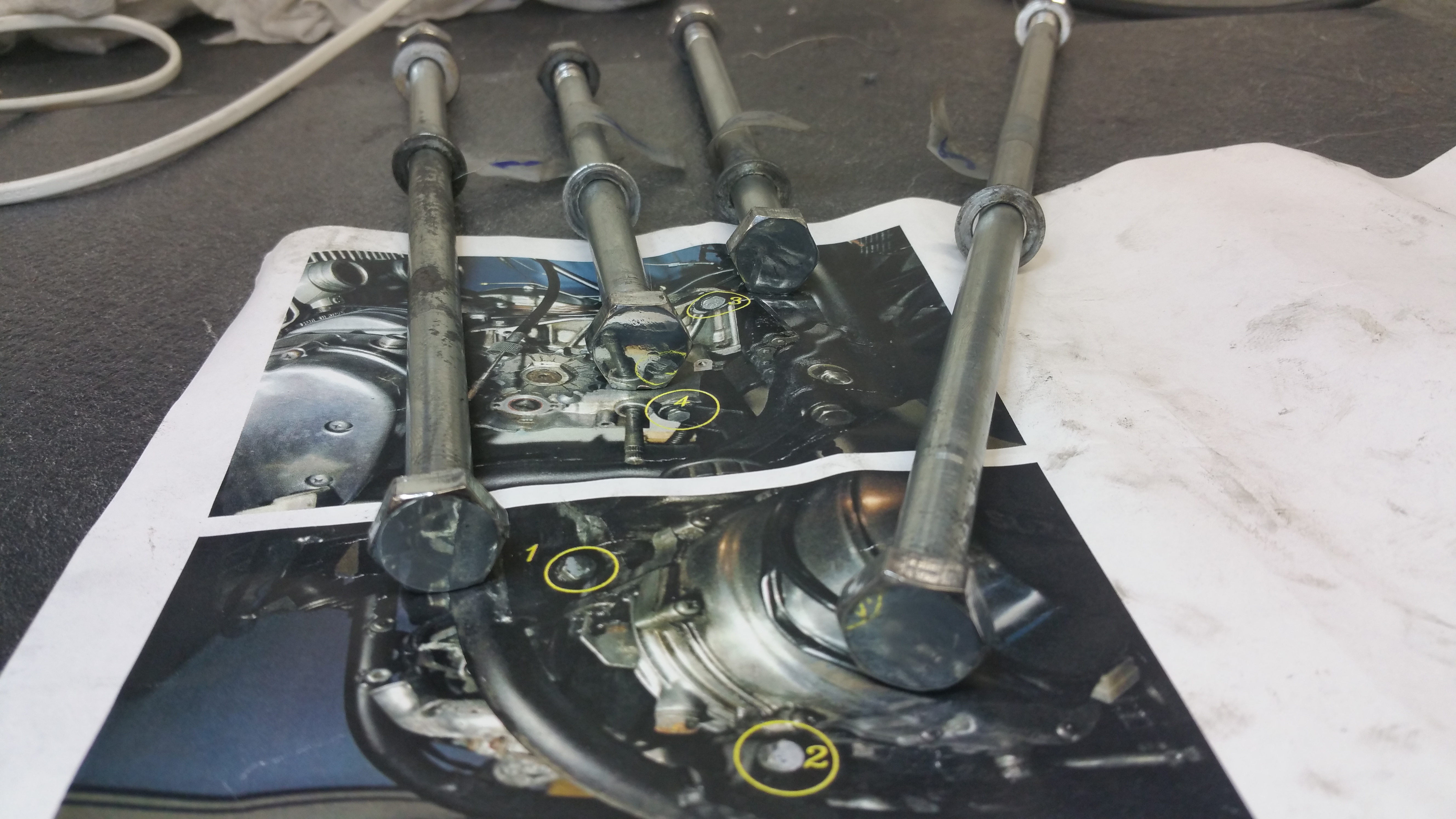
First some preparation. All four mounting bolts were labeled and shown on a picture taken before the dismounting.
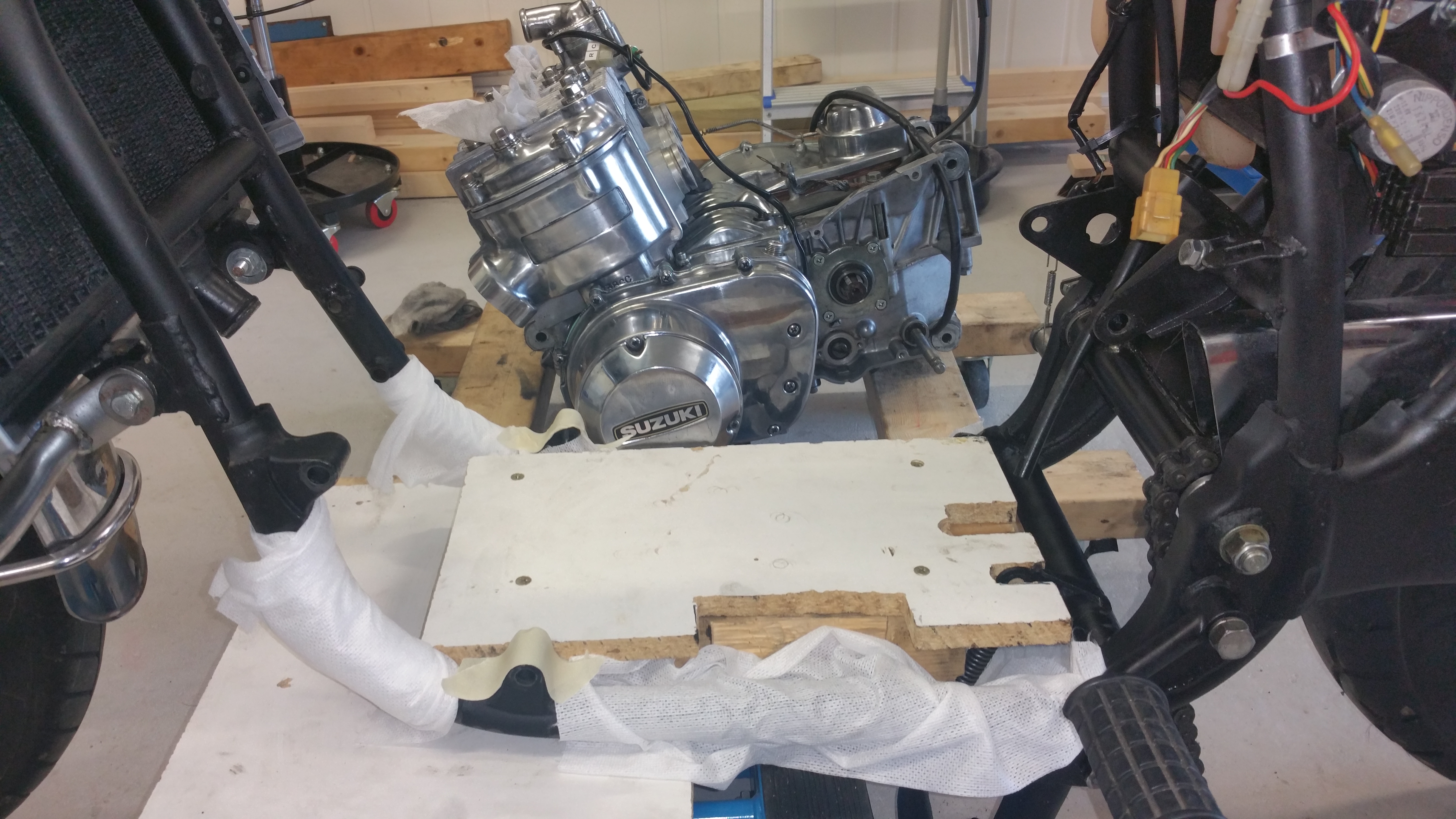
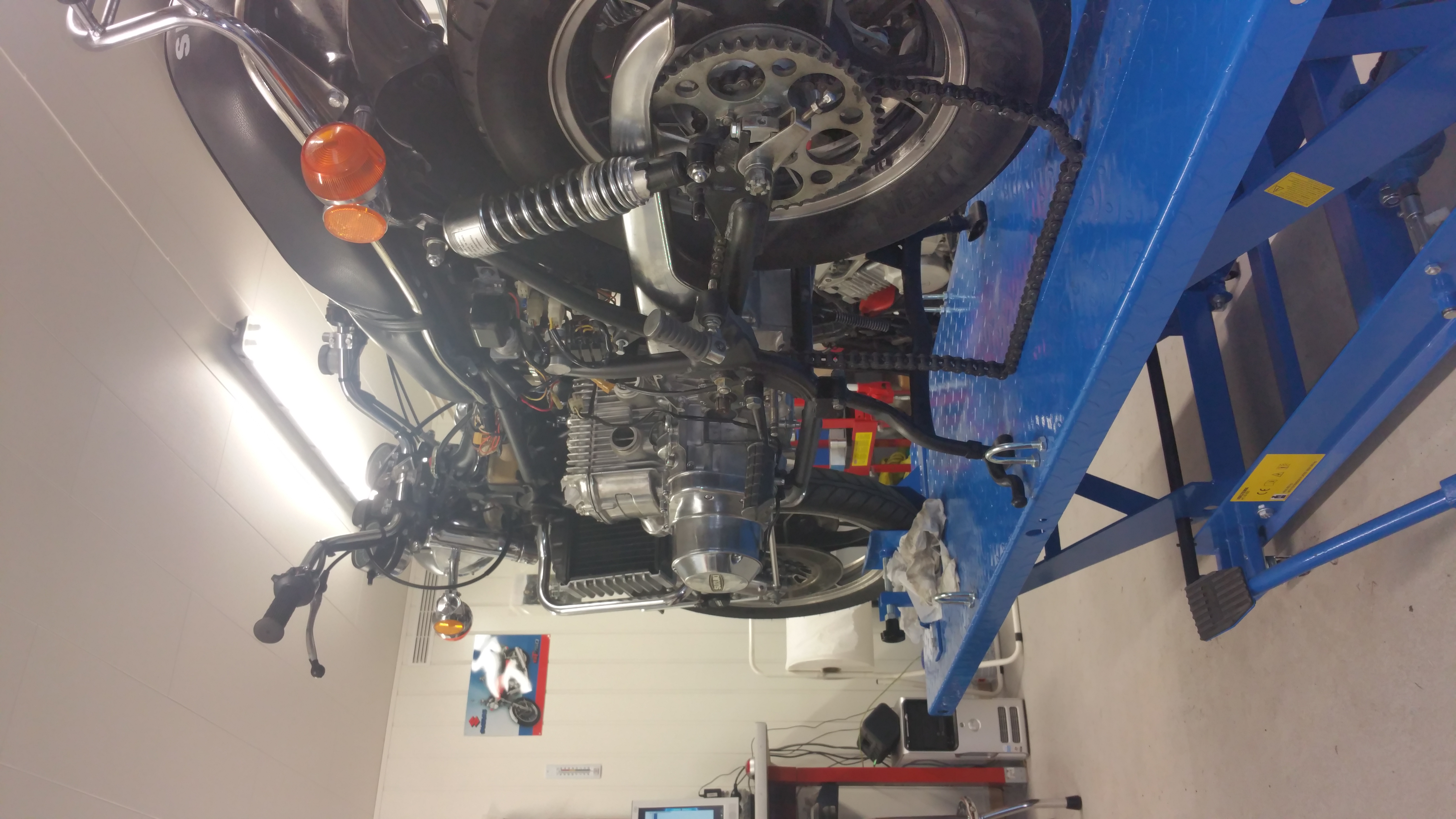
Using the small MC lifter to lower the wood frame.
Well in place on the large MC lifter
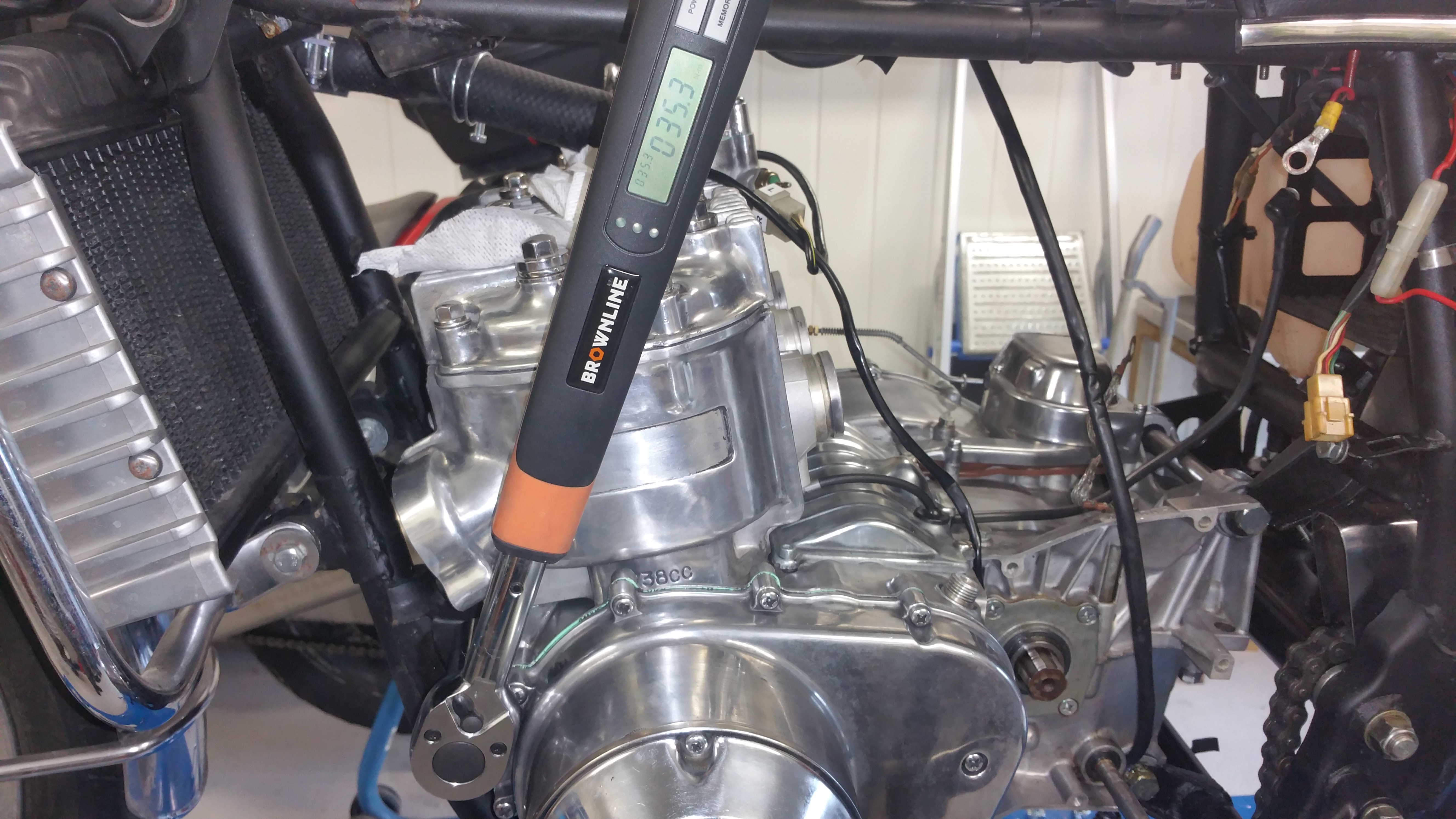
Torque settings : 35 Nm
Cylinder head:
Tightening order (red and green numbers on the bolts ) of cylinder head bolts. Red colour = 35Nm, Green colour = 18Nm
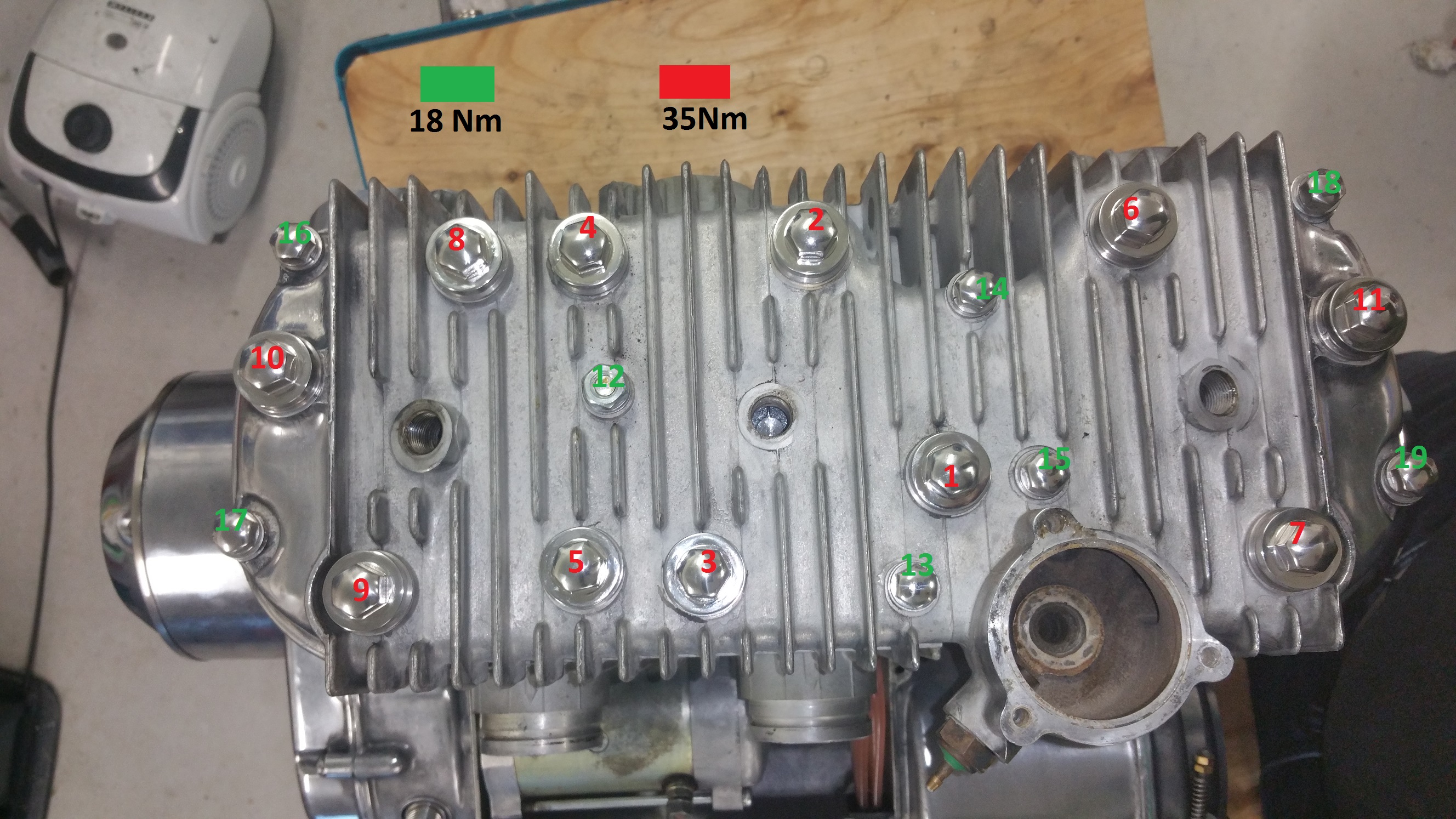
Click on the image for detailed view.
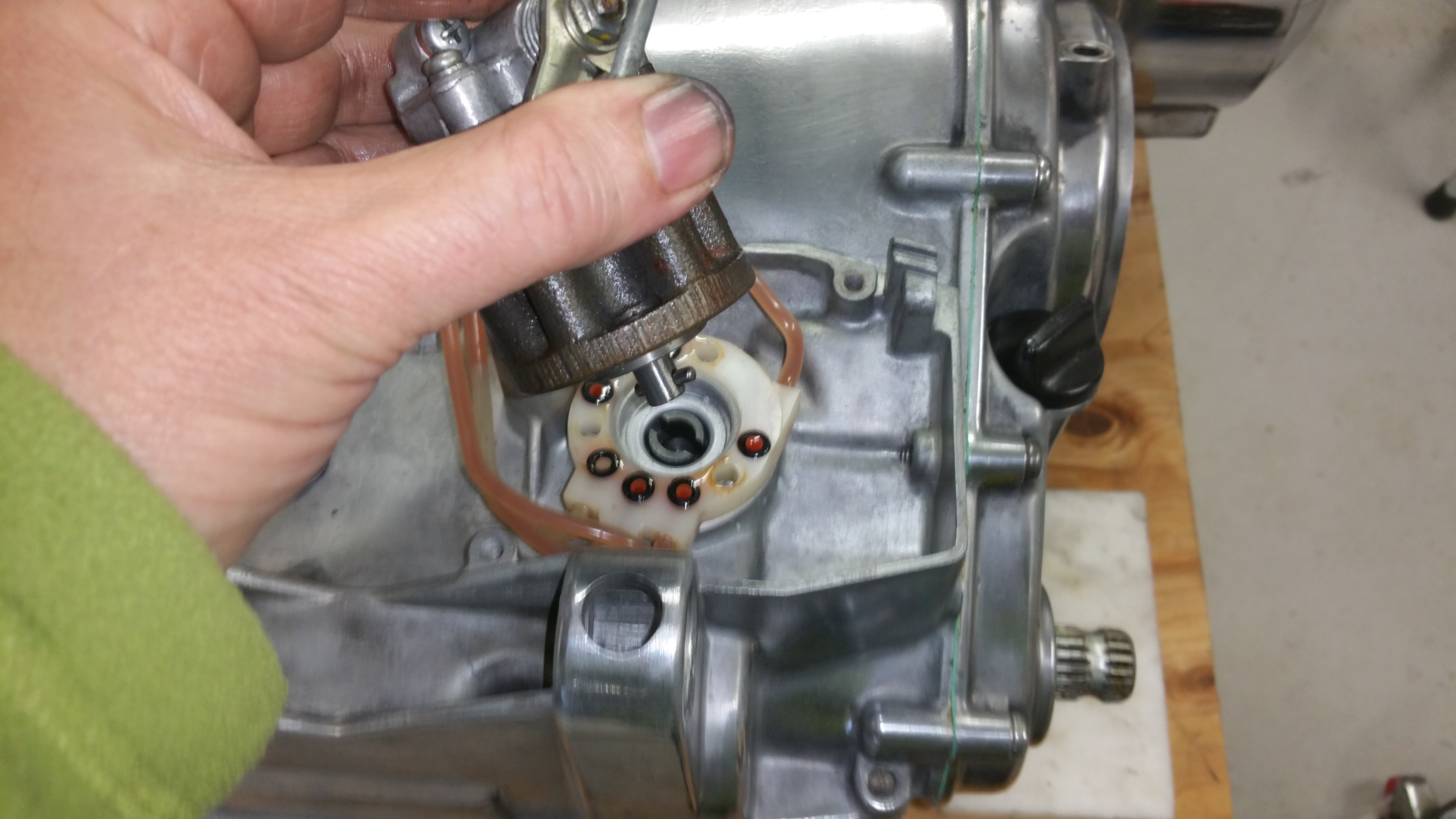
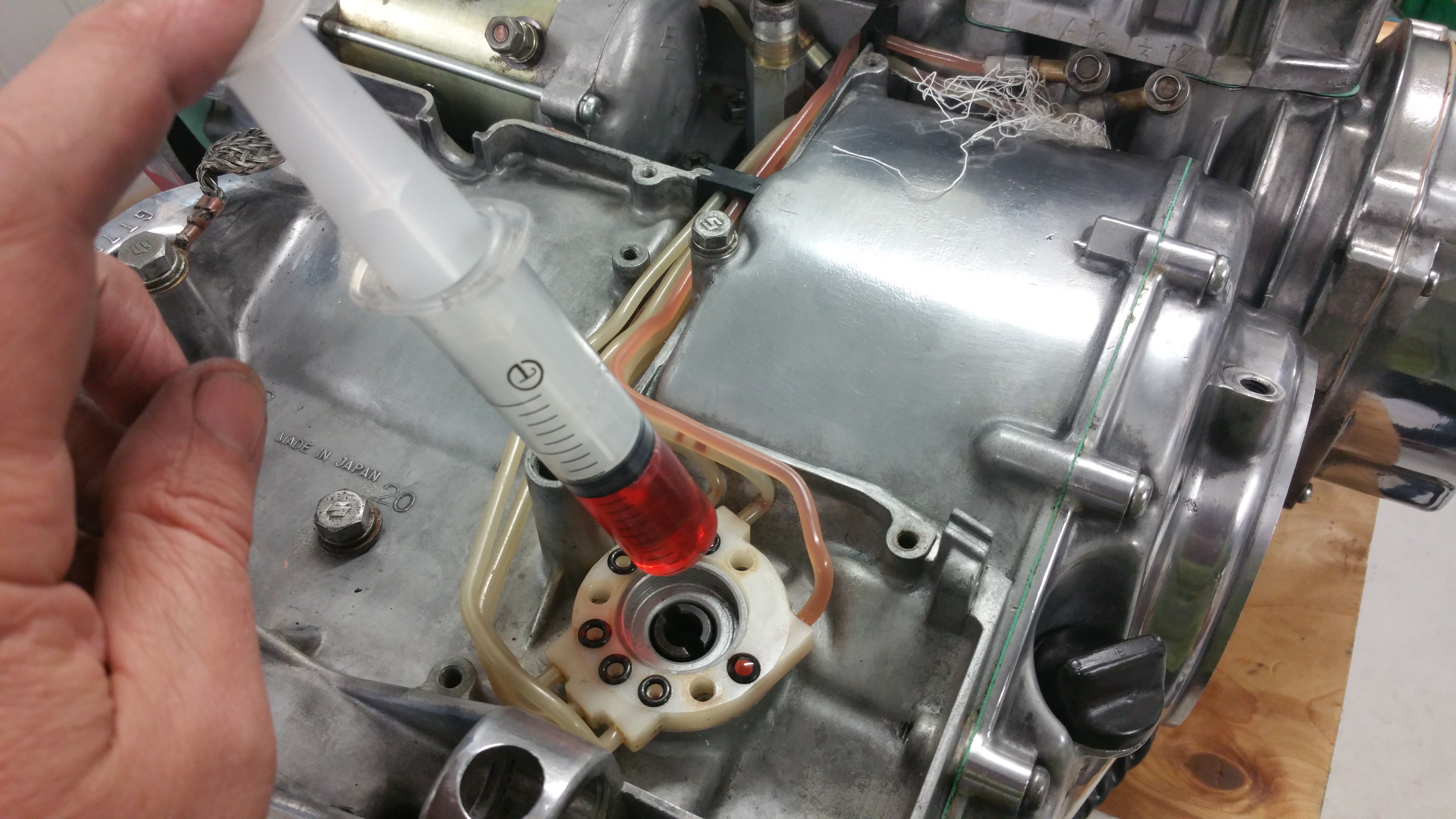
Oil pump and cover :
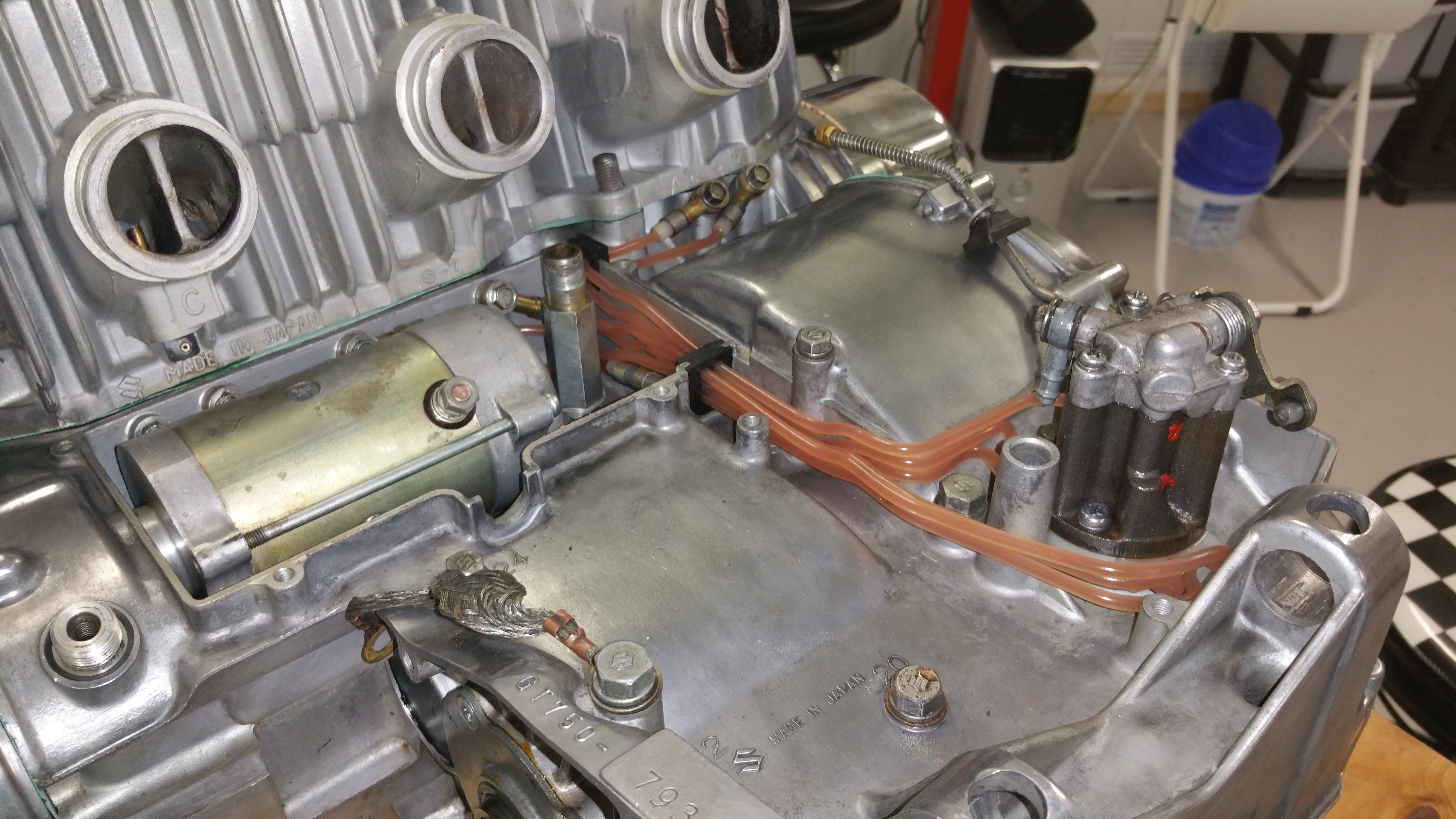
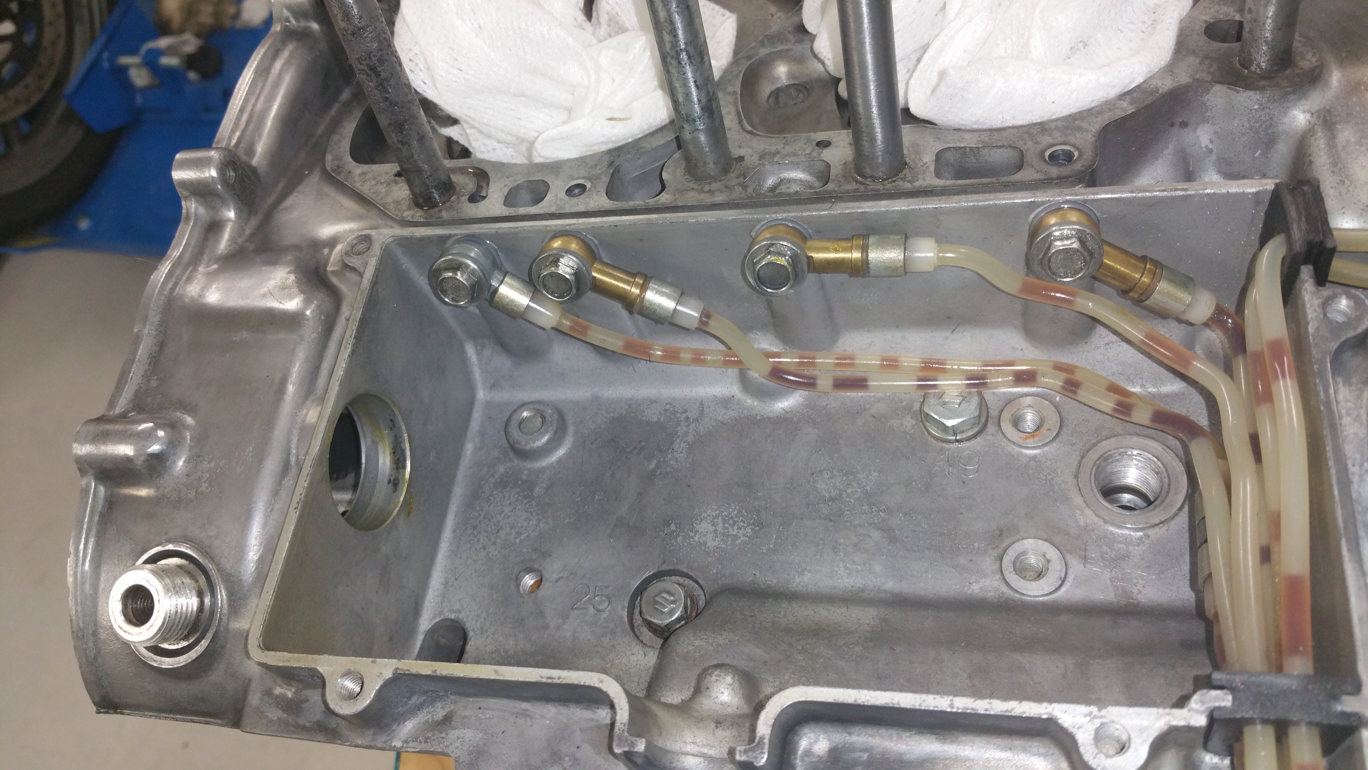
According to the information in fig 1 the SRIS tube from the front side should go from the left cylinder inlet ( see the label C in fig.2) to the center cylinder SRIS outlet port. The SRIS type 2 system. Center to Right and Right to Left, all according to fig.6-13 from the manual
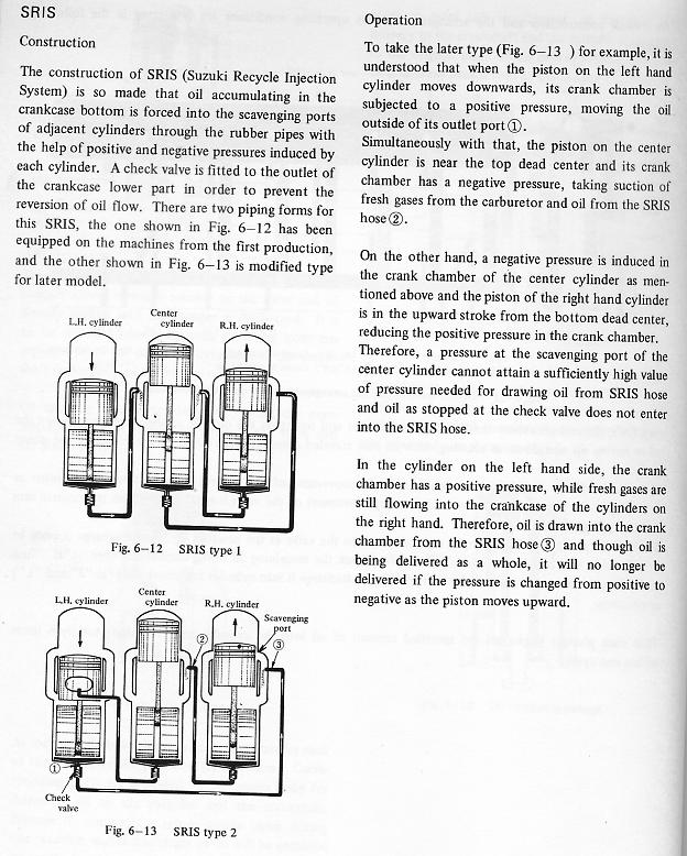
Fig.1
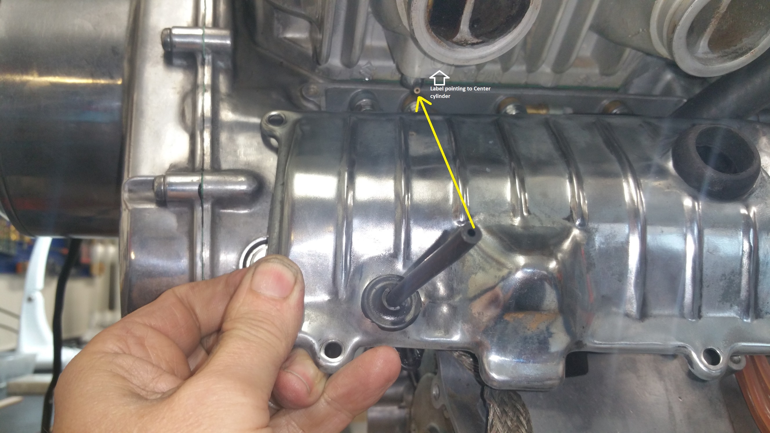
Fig.2
From left cylinder inlet
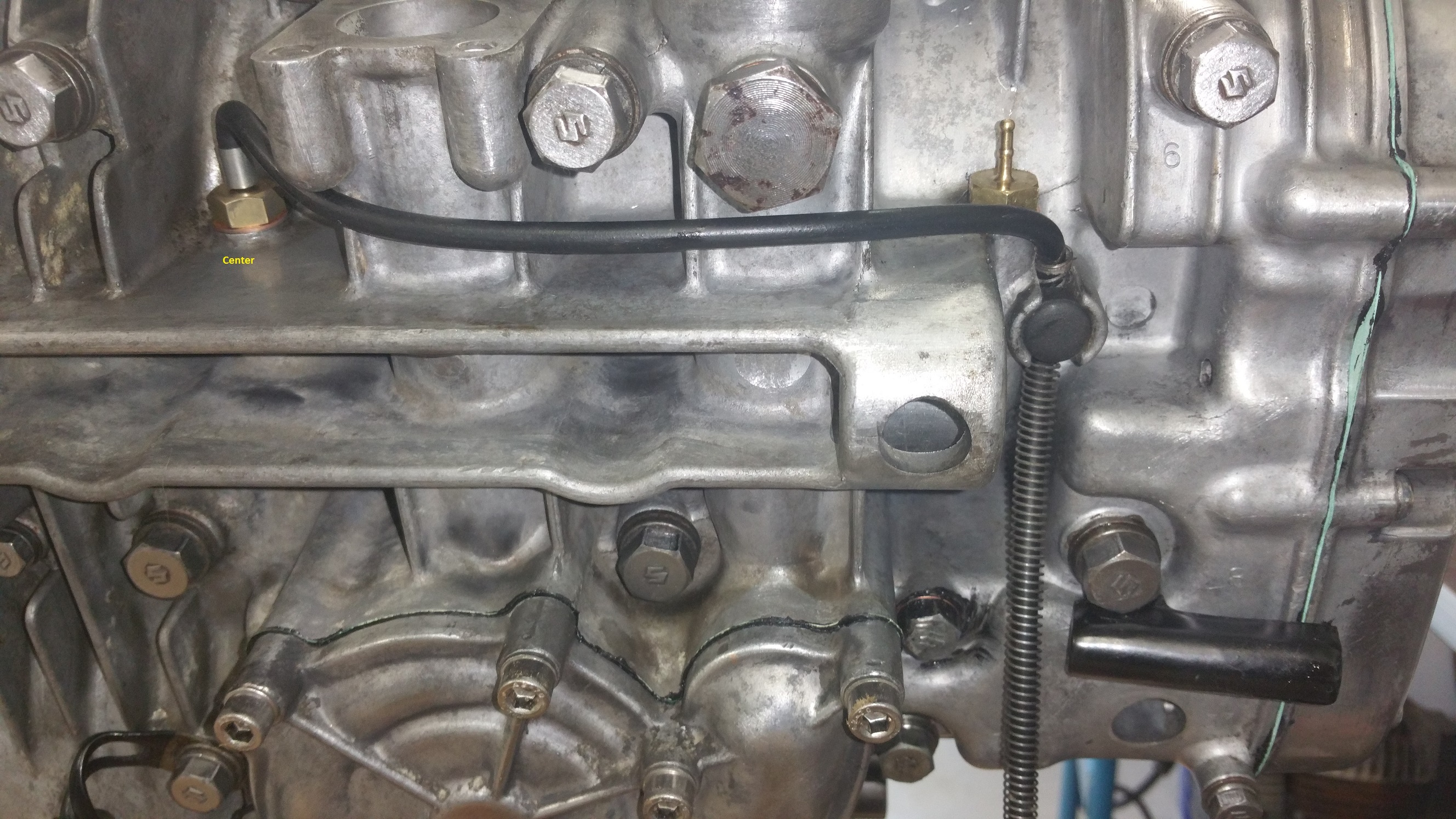
Fig.3
To the Center cylinder SRIS check valve outlet.

Fig.4
Fig.4 shows the two remaining tubes. From Right to Left (red arrow) and Center to Right (yellow arrow ) .
Did the mounting of the cover on the left hand side today. The cover will also house the timing plate, points and capacitors.
I was advised to add some silicone gasket in addition to the new paper gasket, please see the pictures.

Add silicone.
Don’t add silicone where I have the yellow marker. I did it wrong and had to wipe it off after the mounting.
Mount the gasket. I had both alignment studs in the cover and therefore I put the gasket as shown.
Add silicone gasket.
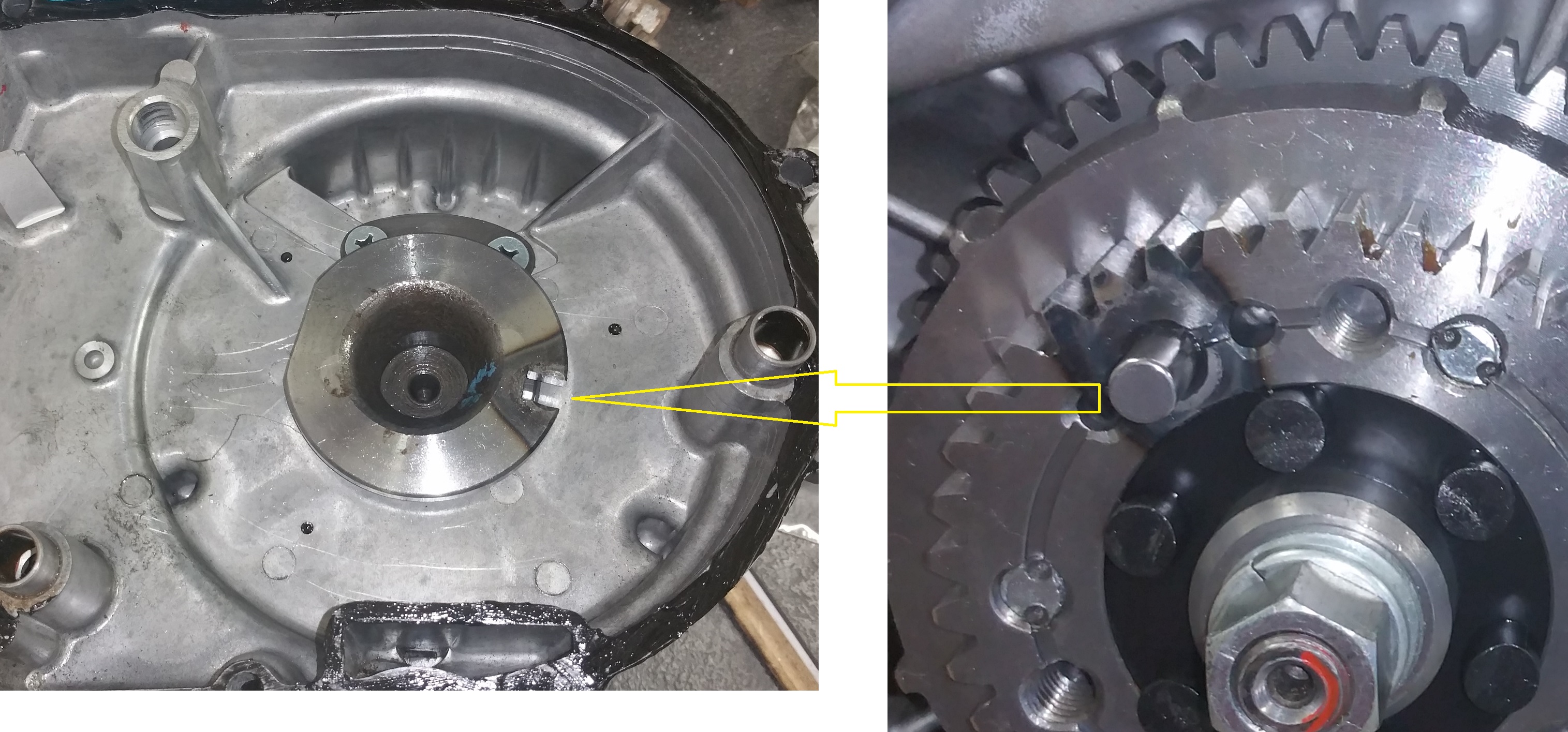
To be able to align the side cover in its correct position the pin must hit the hole in the disk rotating the timing camshaft. Be gentle and don’t use force. Rotate a bit to left and right until the cover snap on.

I still had the original screws. Did some polishing on the heads before the mounting.
Done !
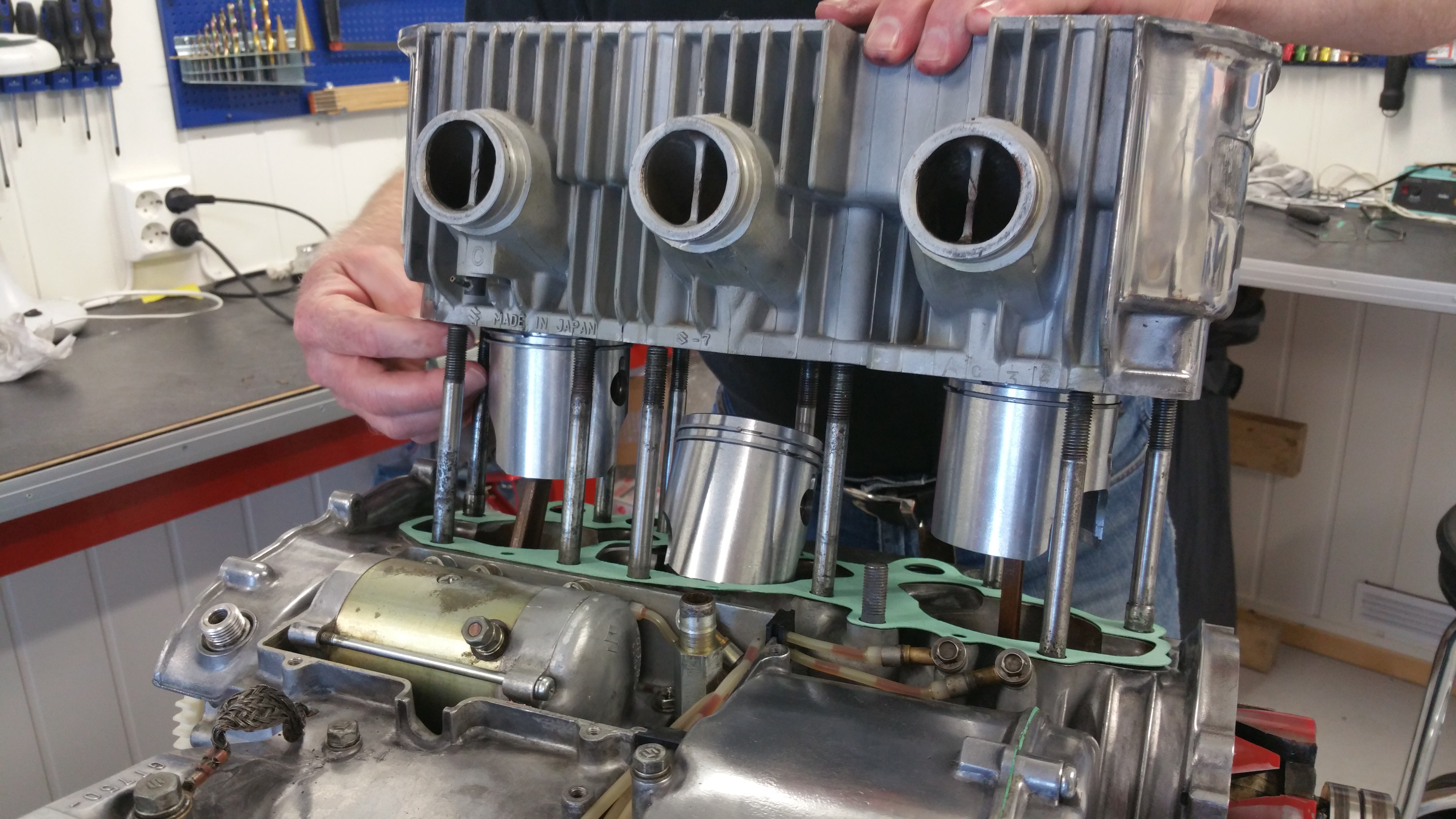
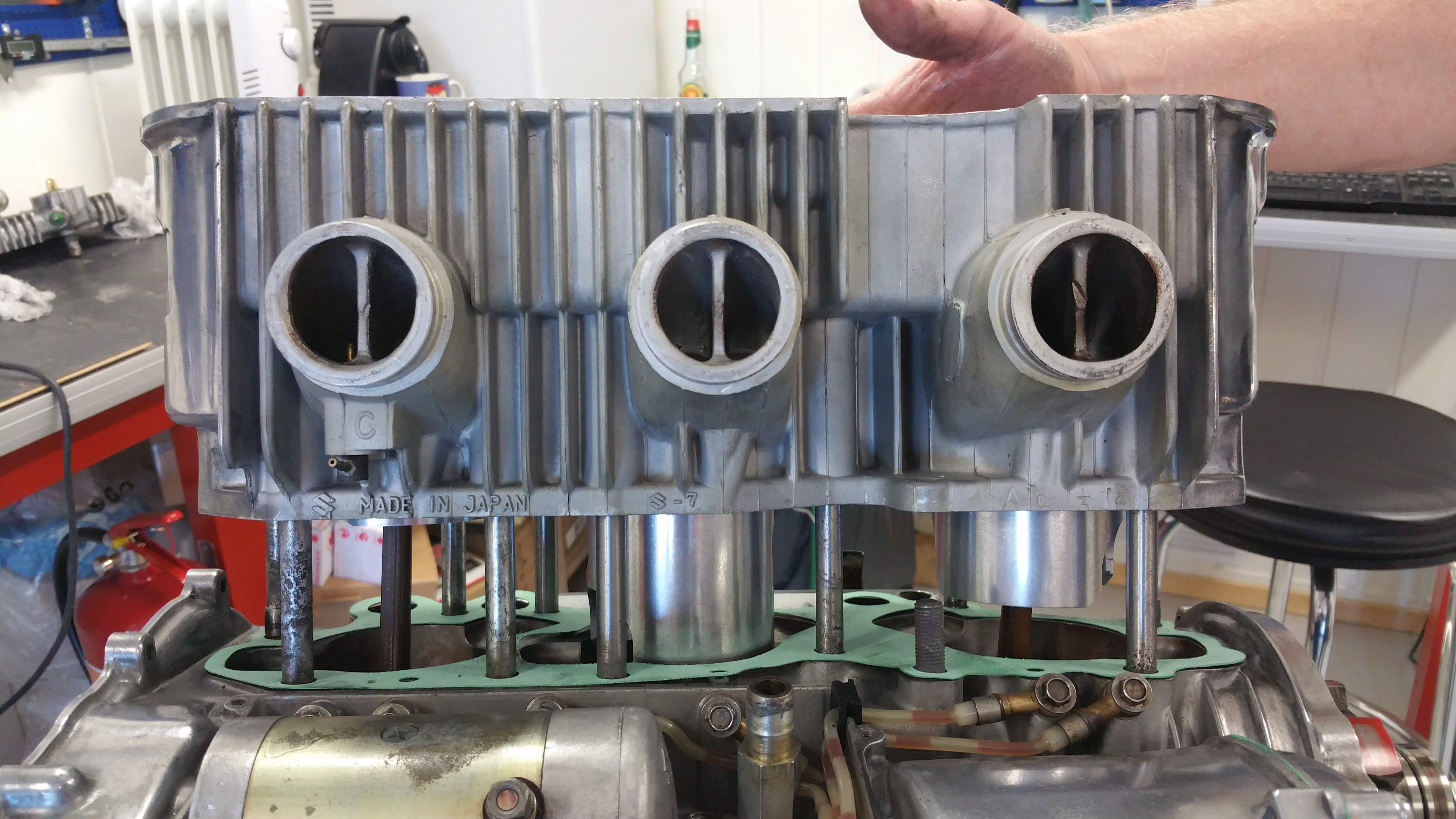
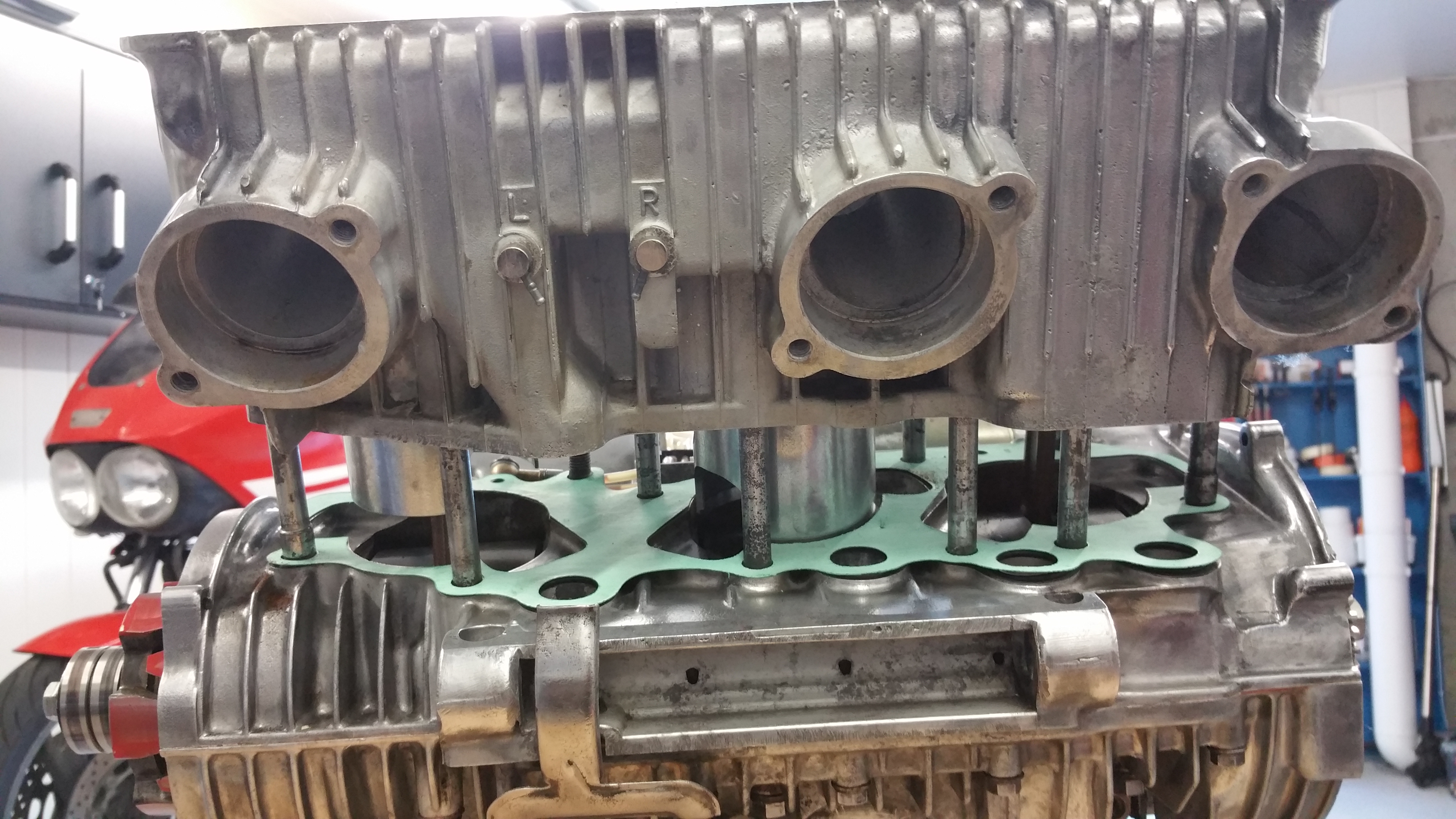
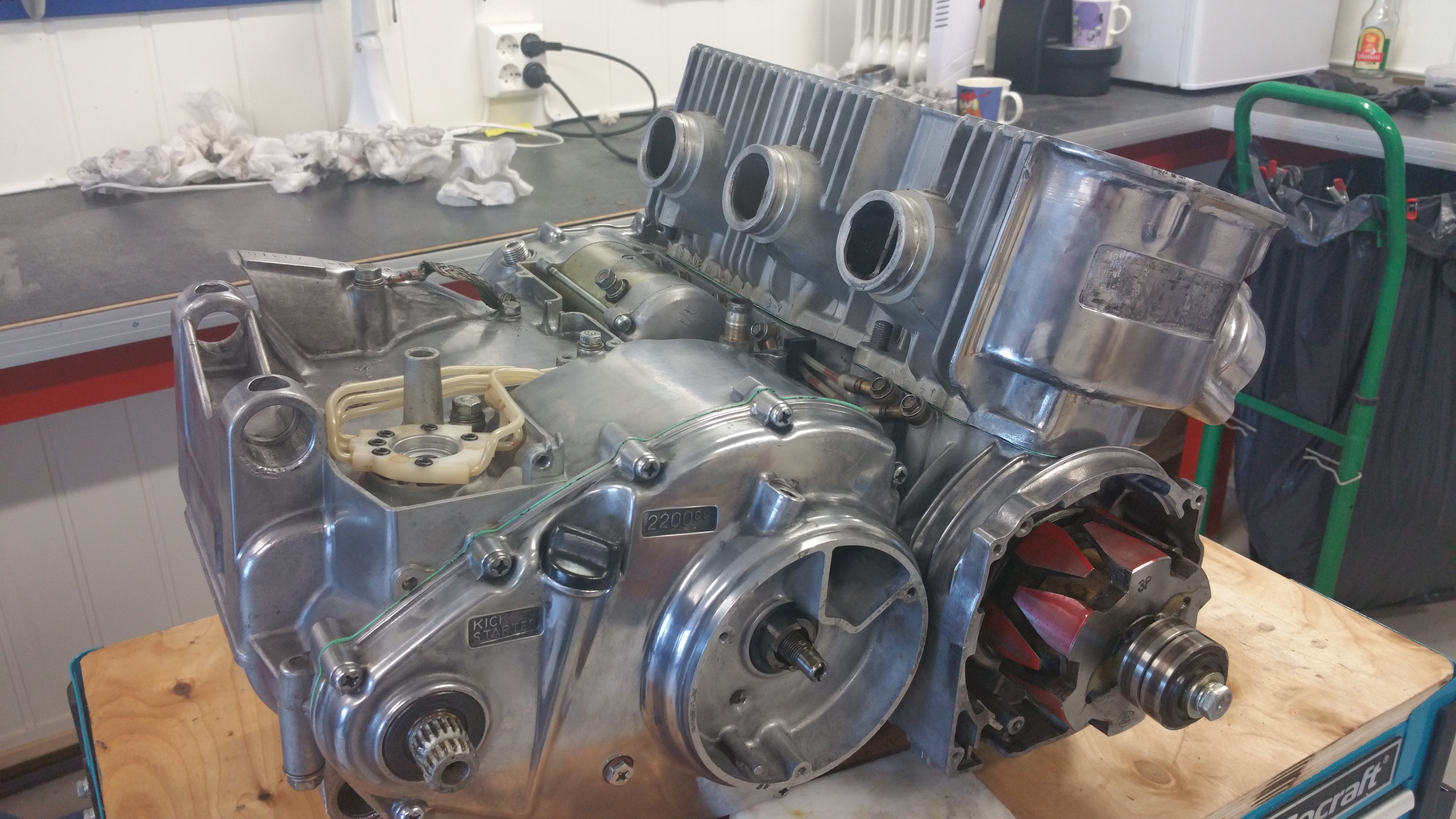
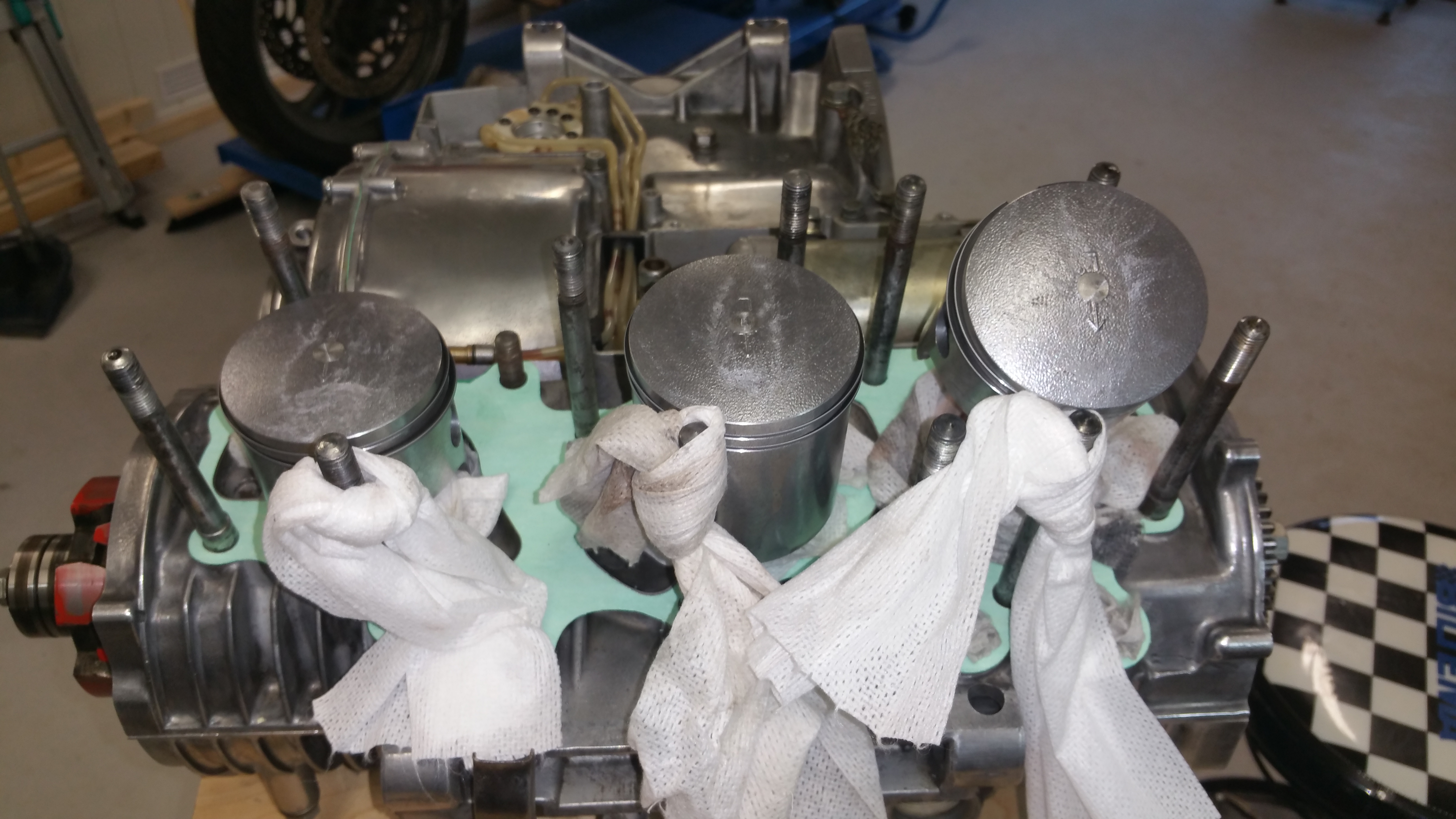
The difficult job is done, got the cylinder block down onto the pistons without breaking any of the piston rings. Got a helping hand from a friend, was too scared to do it alone.
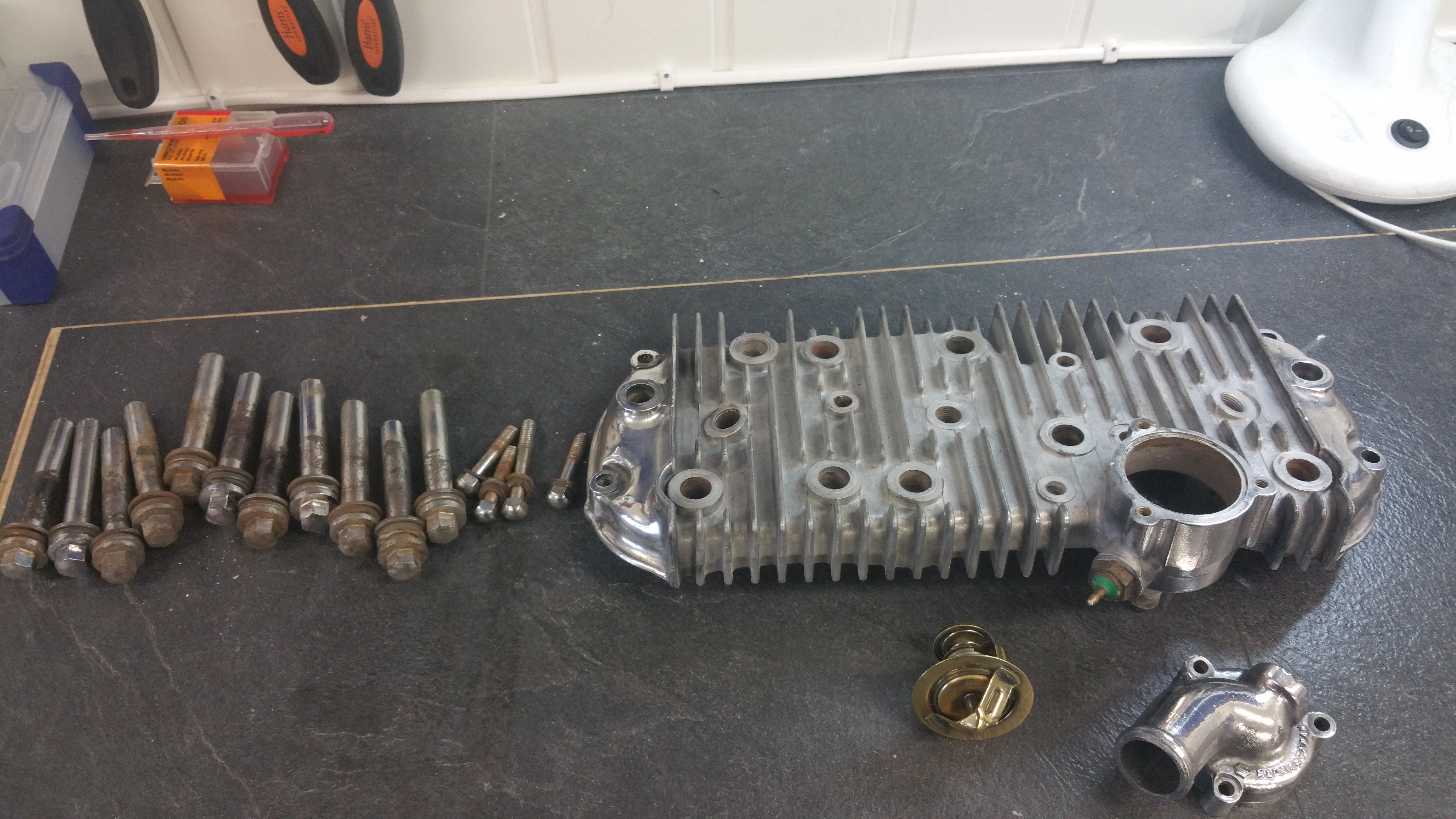
Hmm, rusty bolts. A new kit has been ordered from UK. The attempt to refurbish the old ones was not a success. Let’s hope I soon get the parts and can mount the cylinder head the next weekend.
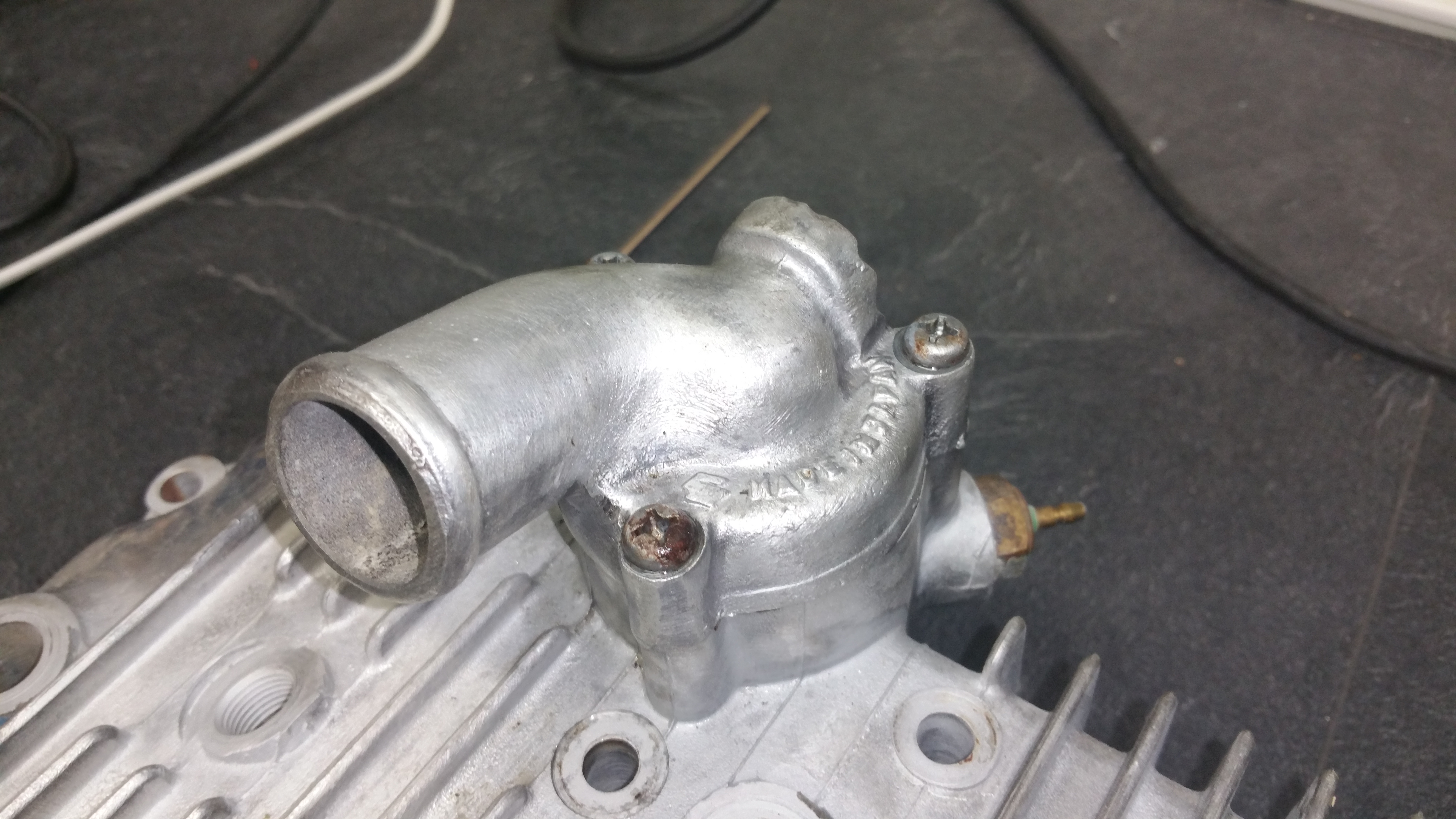
Step 1. Remove the thermostat housing
Not an easy task, all of three screws were stuck. Applied some anti rust solvent and went ahead with the job the next day.
The housing were heated up by using a butane torch and in addition I used an impact screwdriver to get the screws loose.
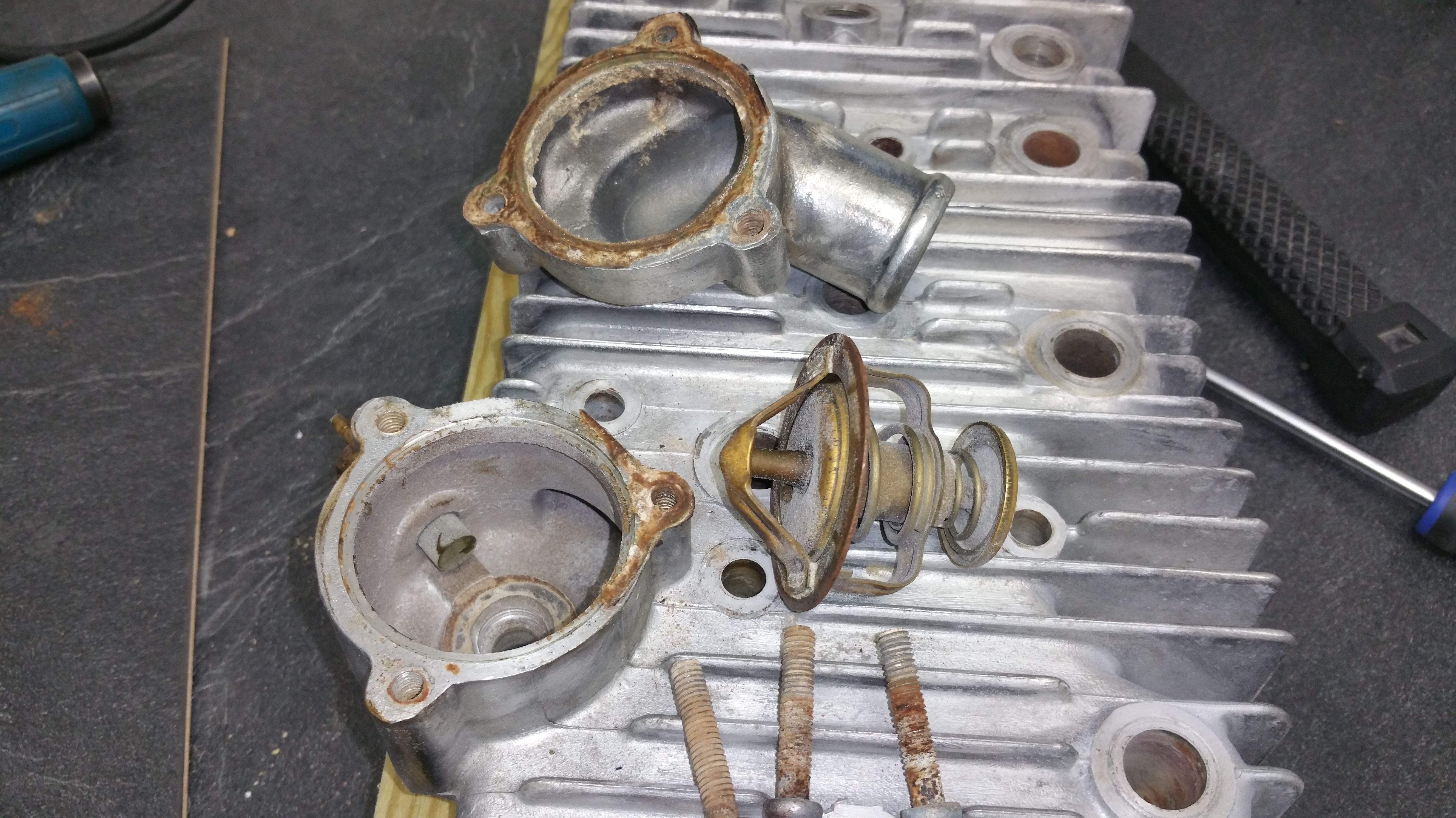
Finally I had the parts separated
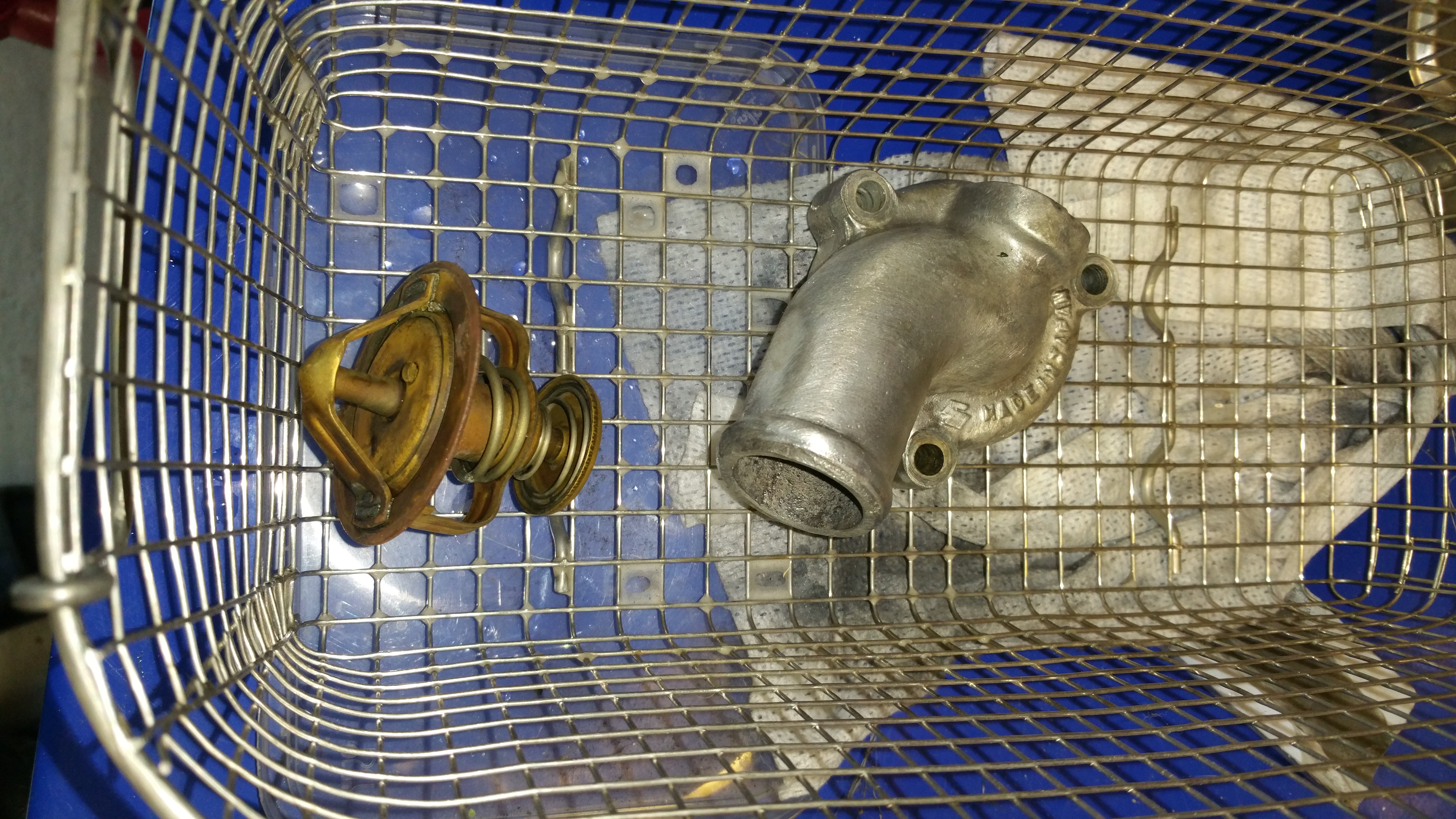
Cleaning of the parts using the ultrasonic washer
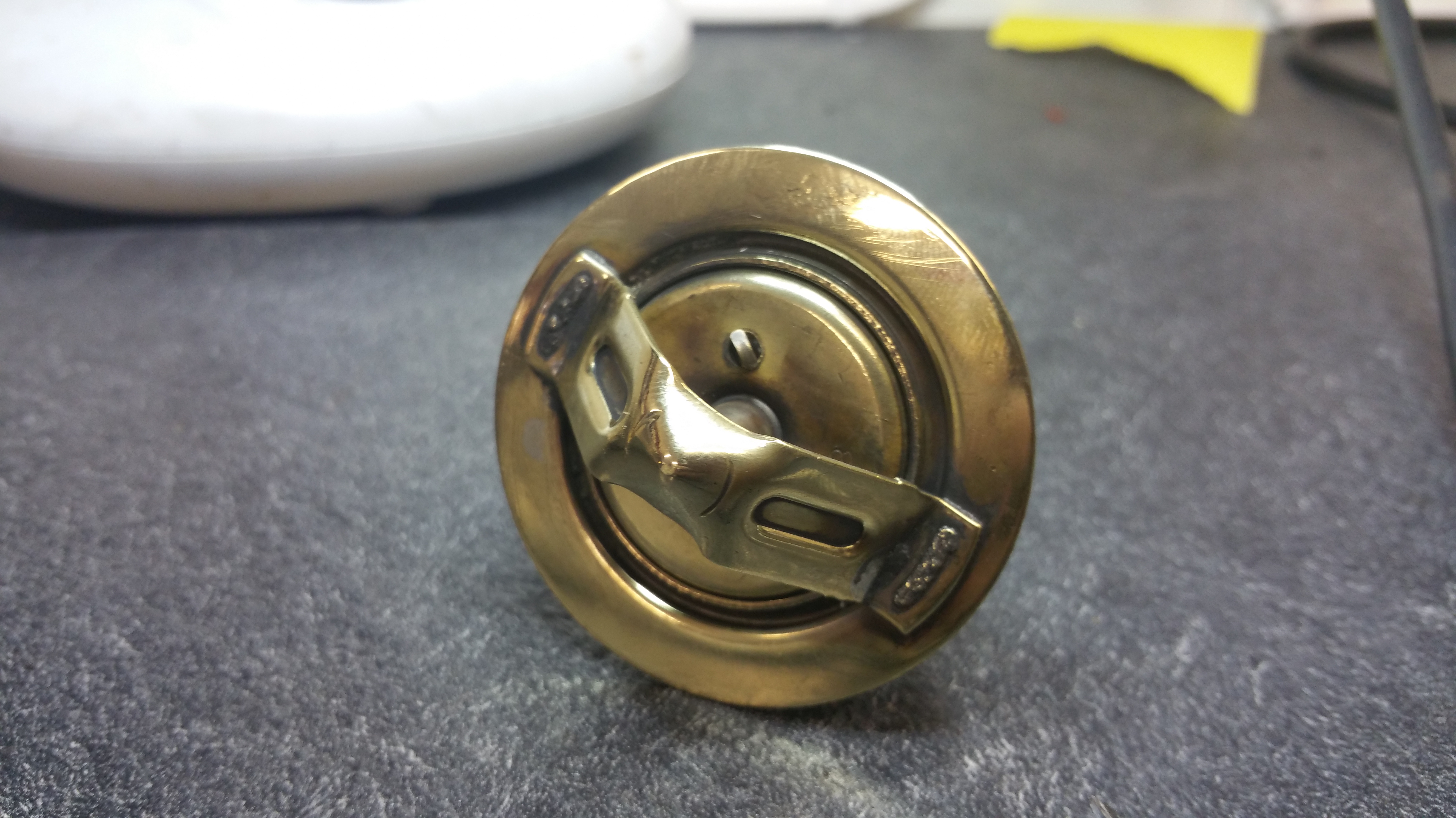
Step 2, verify the function of the thermostat:
According to the service manual the vale opening temperature is 82 deg C and wide open (8mm) at 95 deg C.
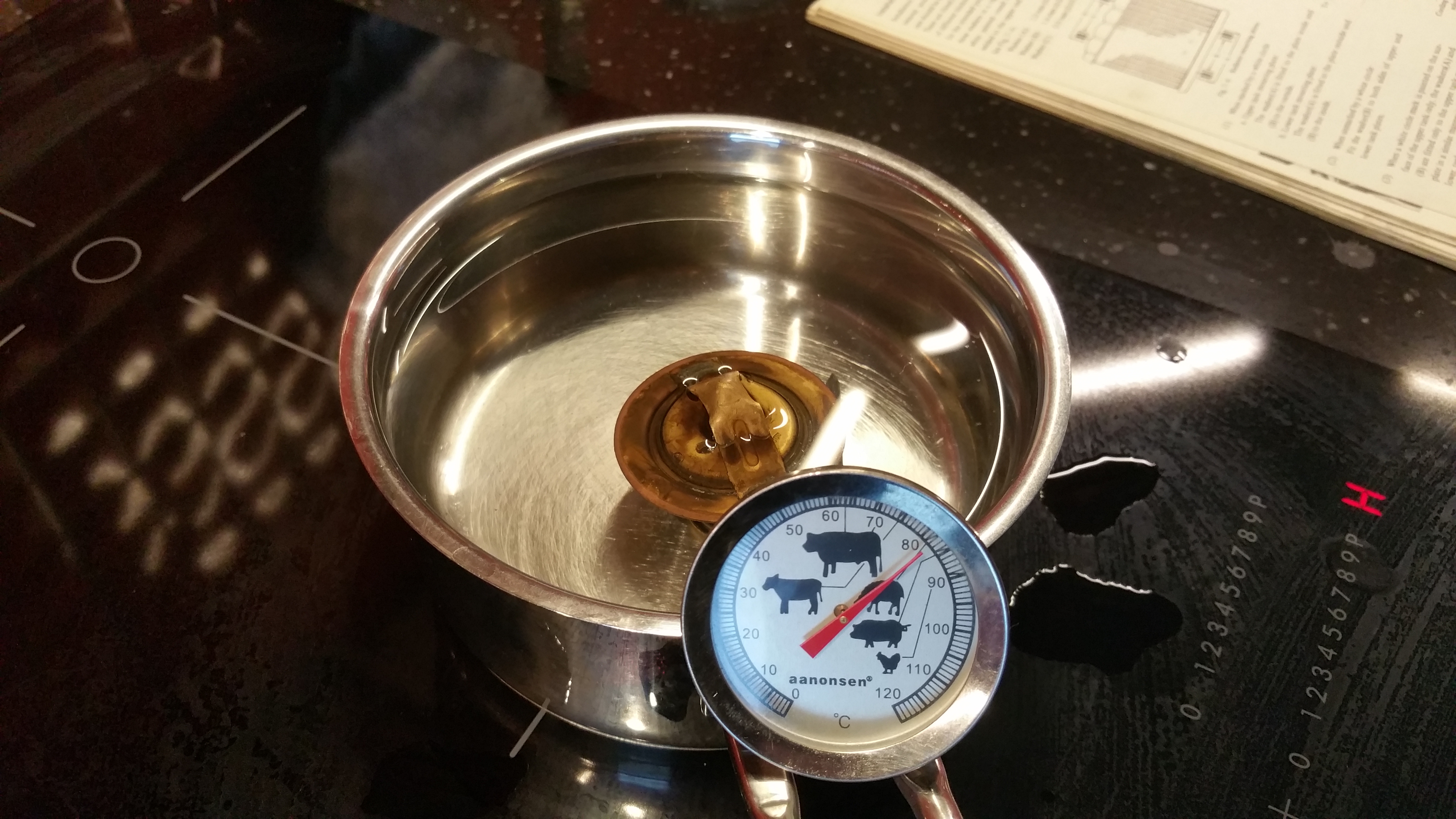
82 deg C and closed
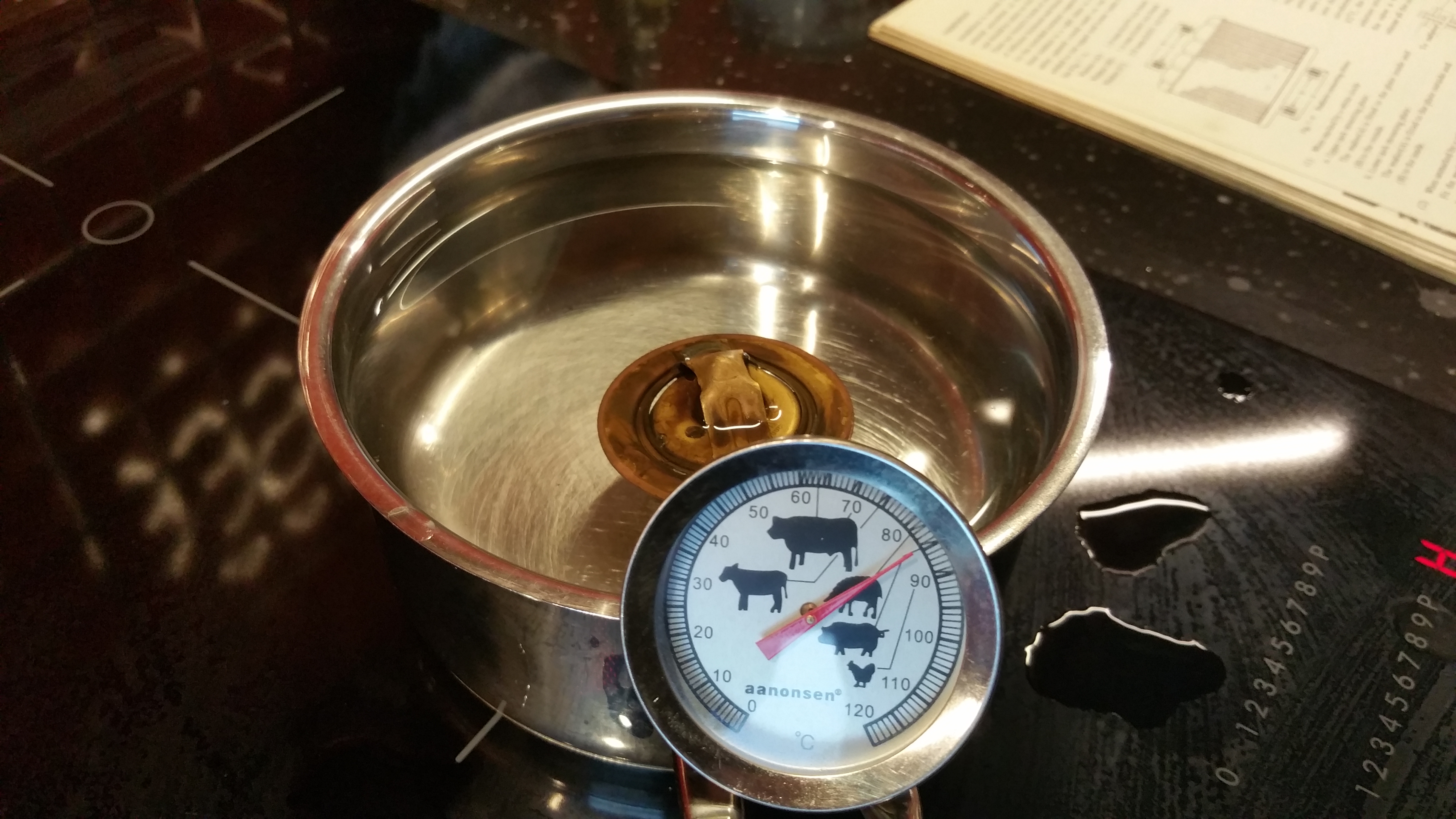
85 deg C and half opened
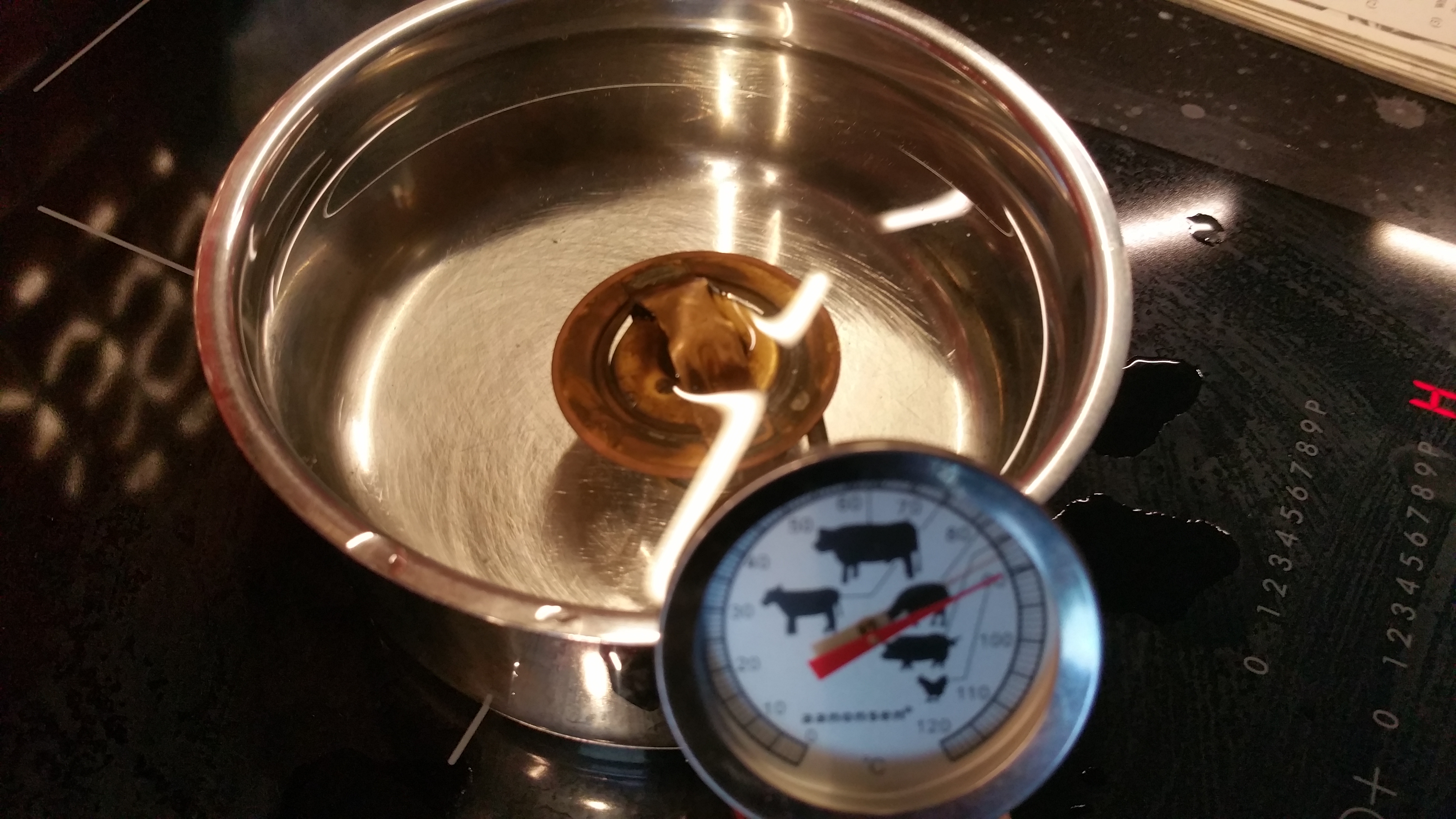
90 deg C and almost fully opened
Good to go, the thermostat is functioning as specified.
Thermostat response time:
See how it’s closing only seconds after it is out of the boiling water.
Step 3, polishing the thermostat housing:
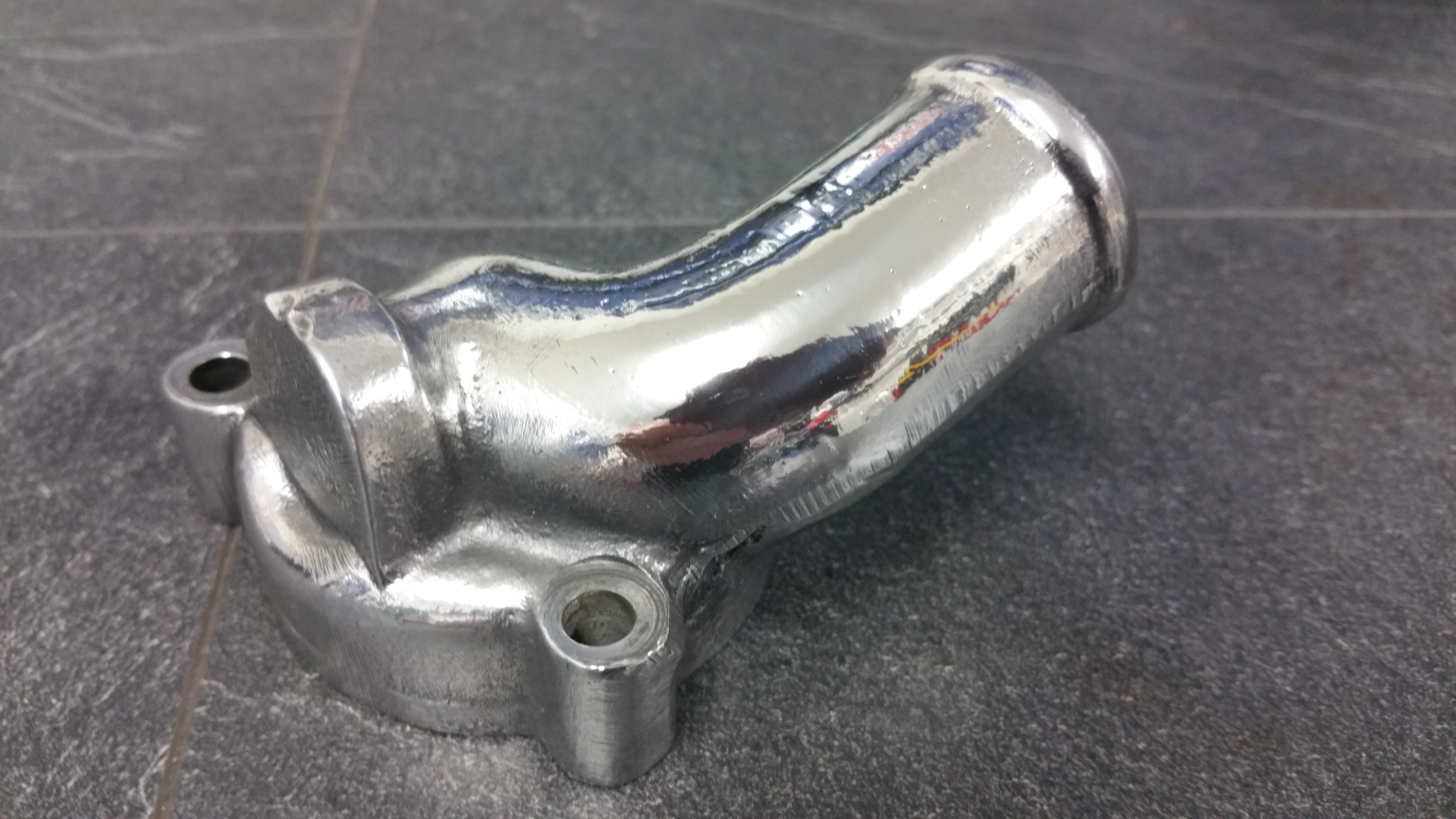
Nice and shiny 🙂
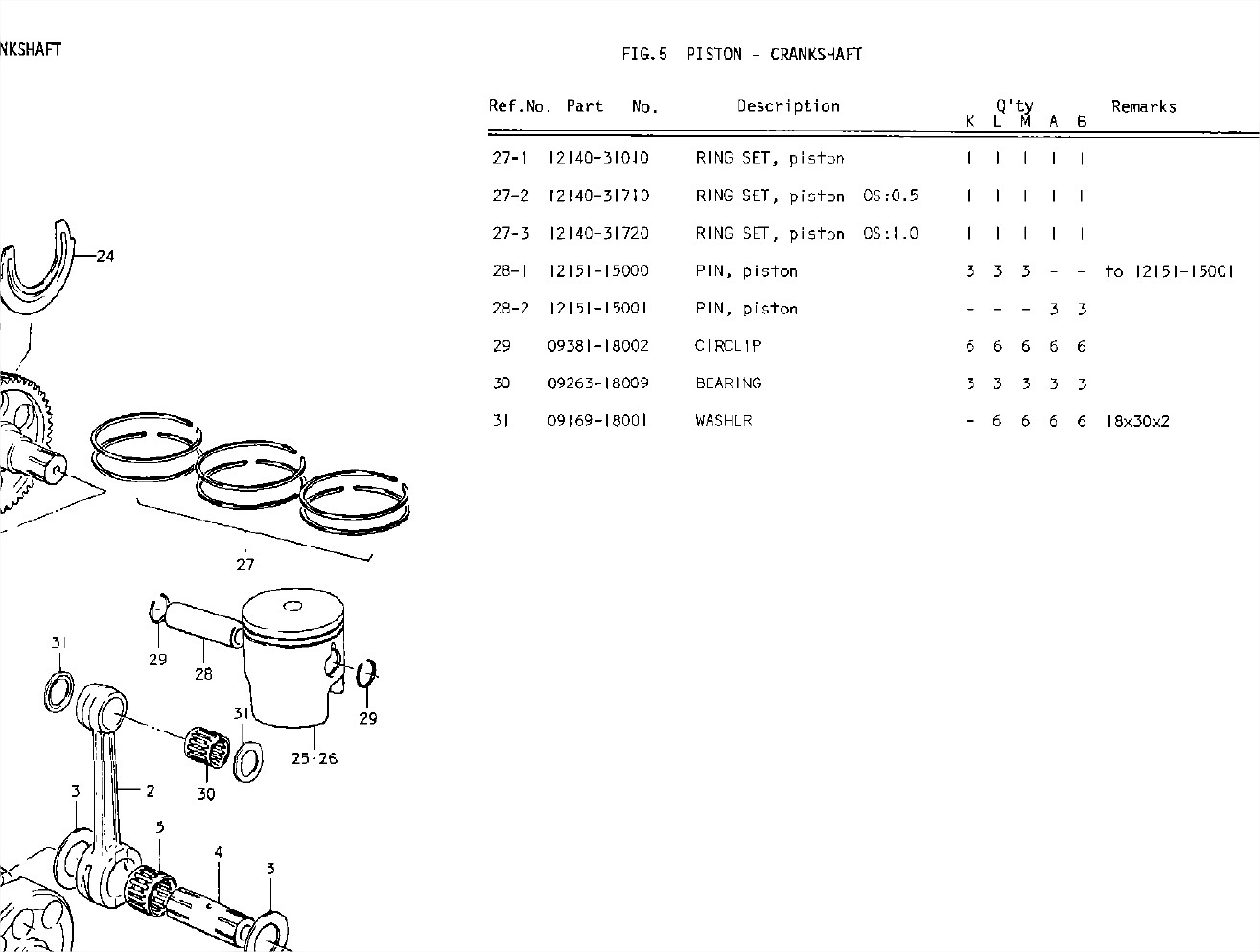
New parts to be mounted

Step 1: Circlip
Mount one circlip in all three pistons. Move the end position away from the cutout. Be gentle and don’t bend the circlip too much. Use a screw driver as a tool to flip it into the position in the groove. Always new circlips, never reuse old one.
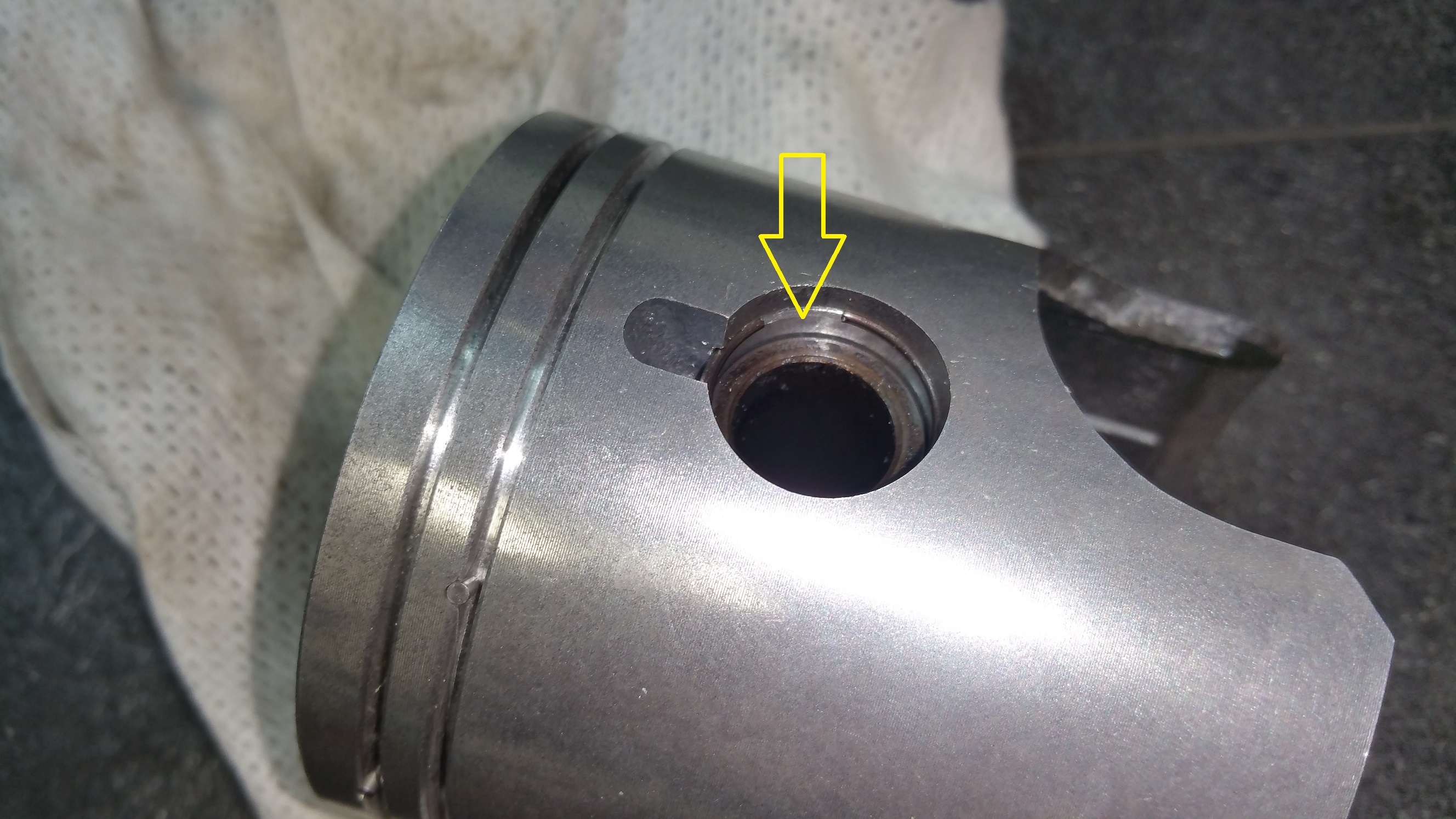
Step 2: Piston rings

Mount the piston ring as shown on the photo. Be aware of the pin locking the ring, see the arrows. You don’t need any special tools for mounting the piston rings. They are quite expensive an if you are afraid of braking any of them, drink a beer before you start 🙂
Step 3: Gasket and O-rings
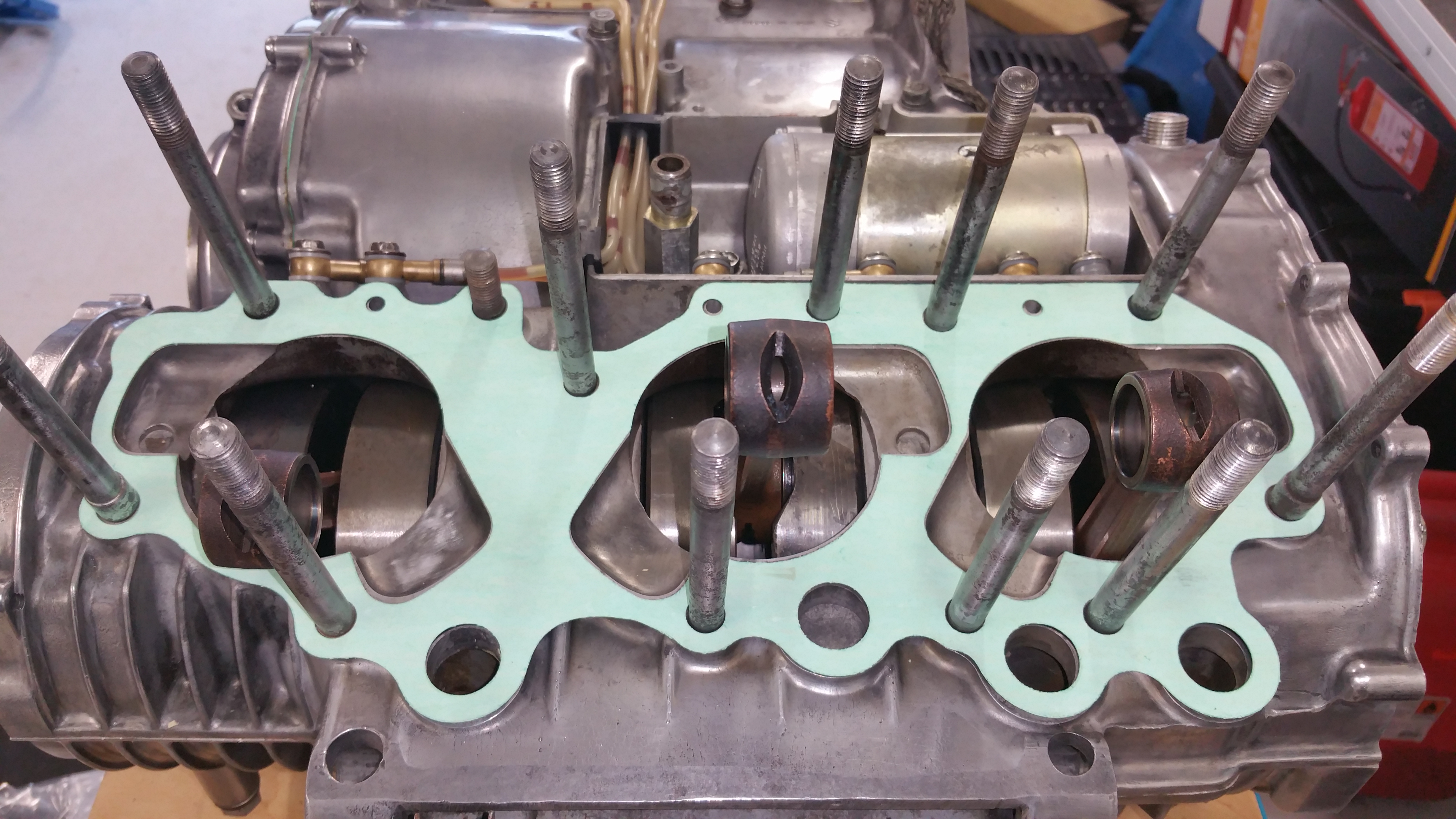
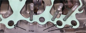
Mount the gasket, don’t forget to mount three O-rings underneath the gasket.
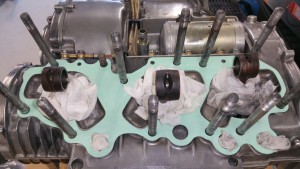
Before you continue, cover all holes so you don’t drop any parts inside the engine. Can be difficult to retrieve.
Step 4: Pistons
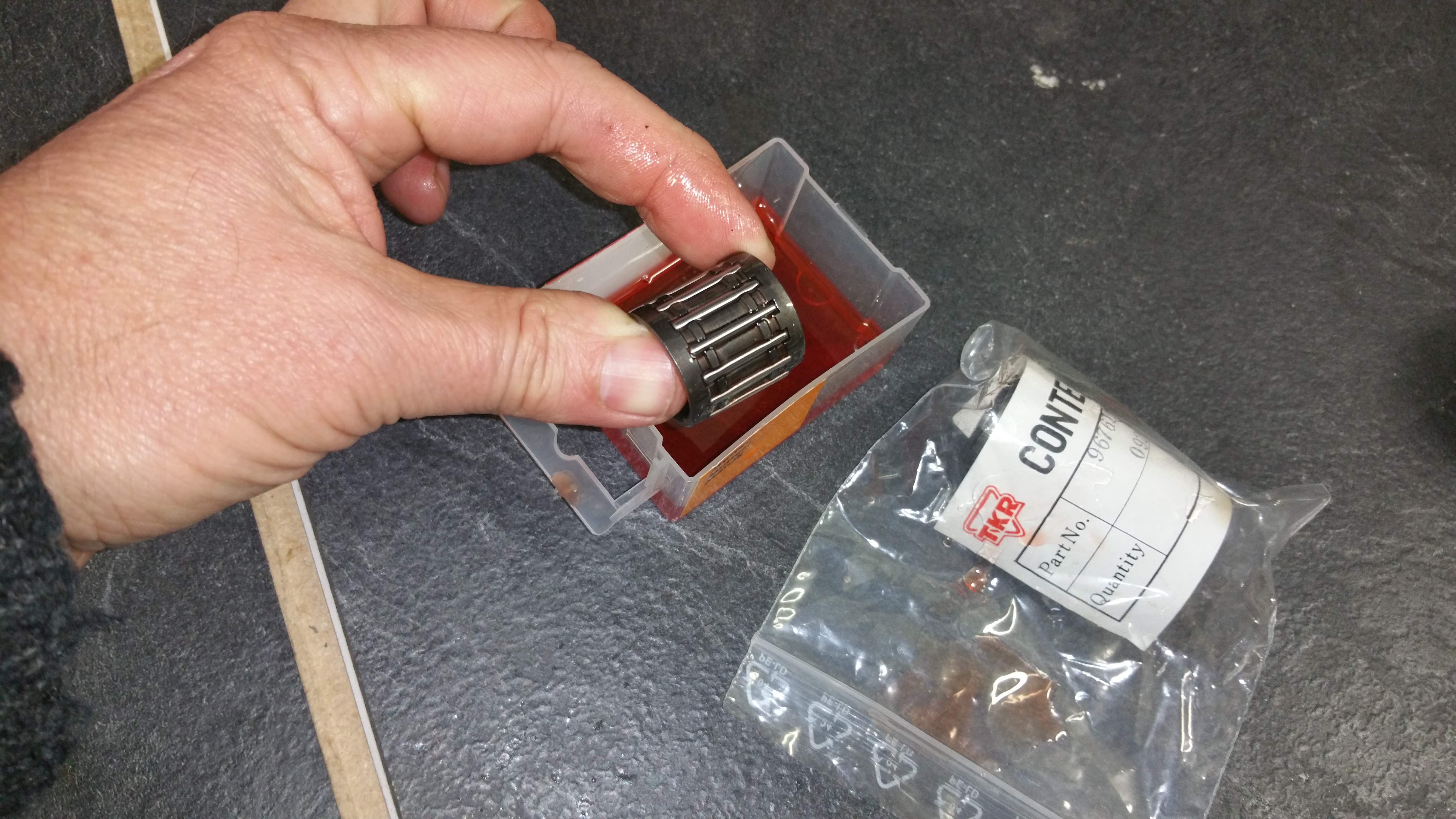
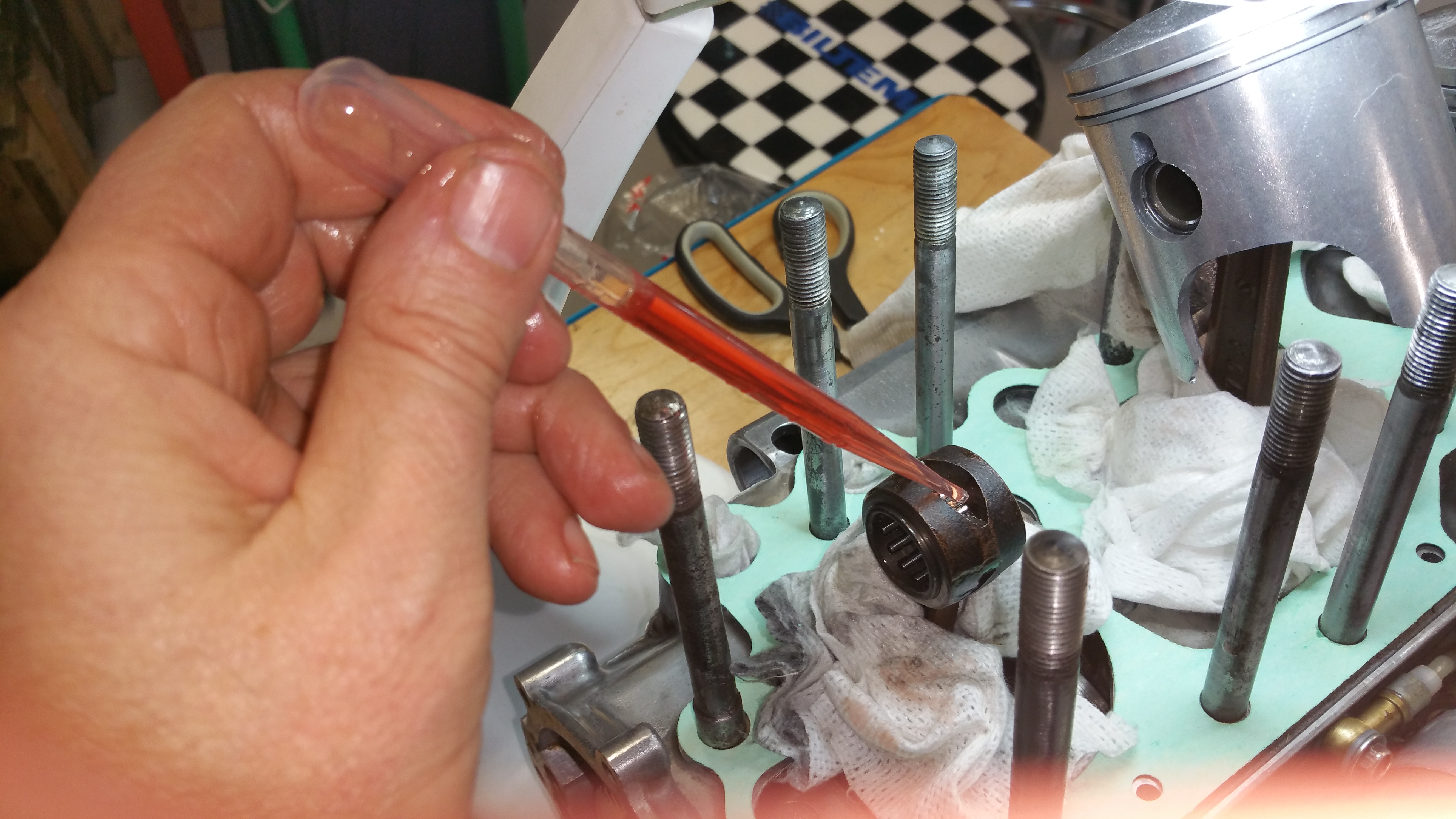
Oil the bearing before and after it’s installed in the rod.
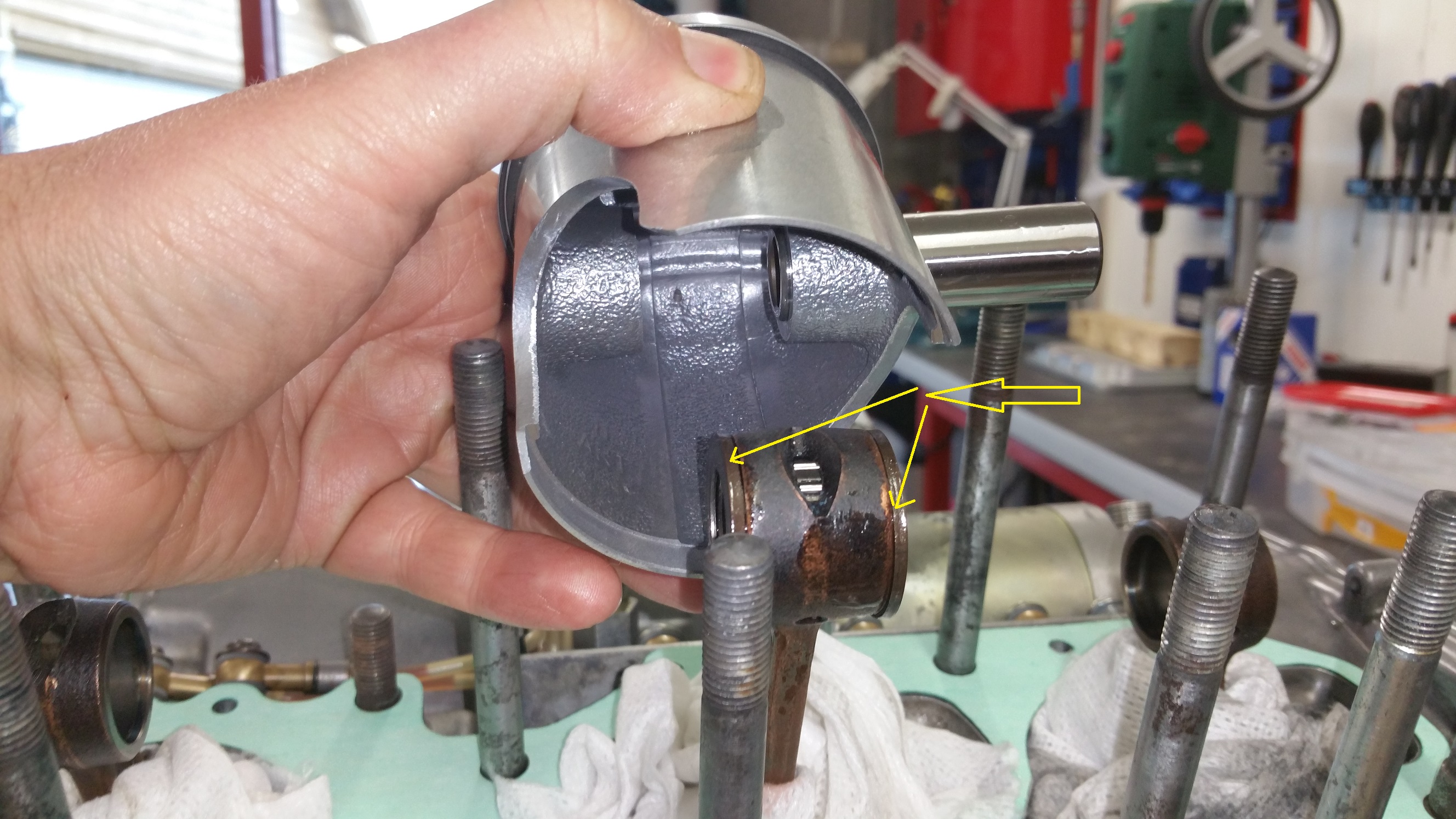
Remeber the washers (31)
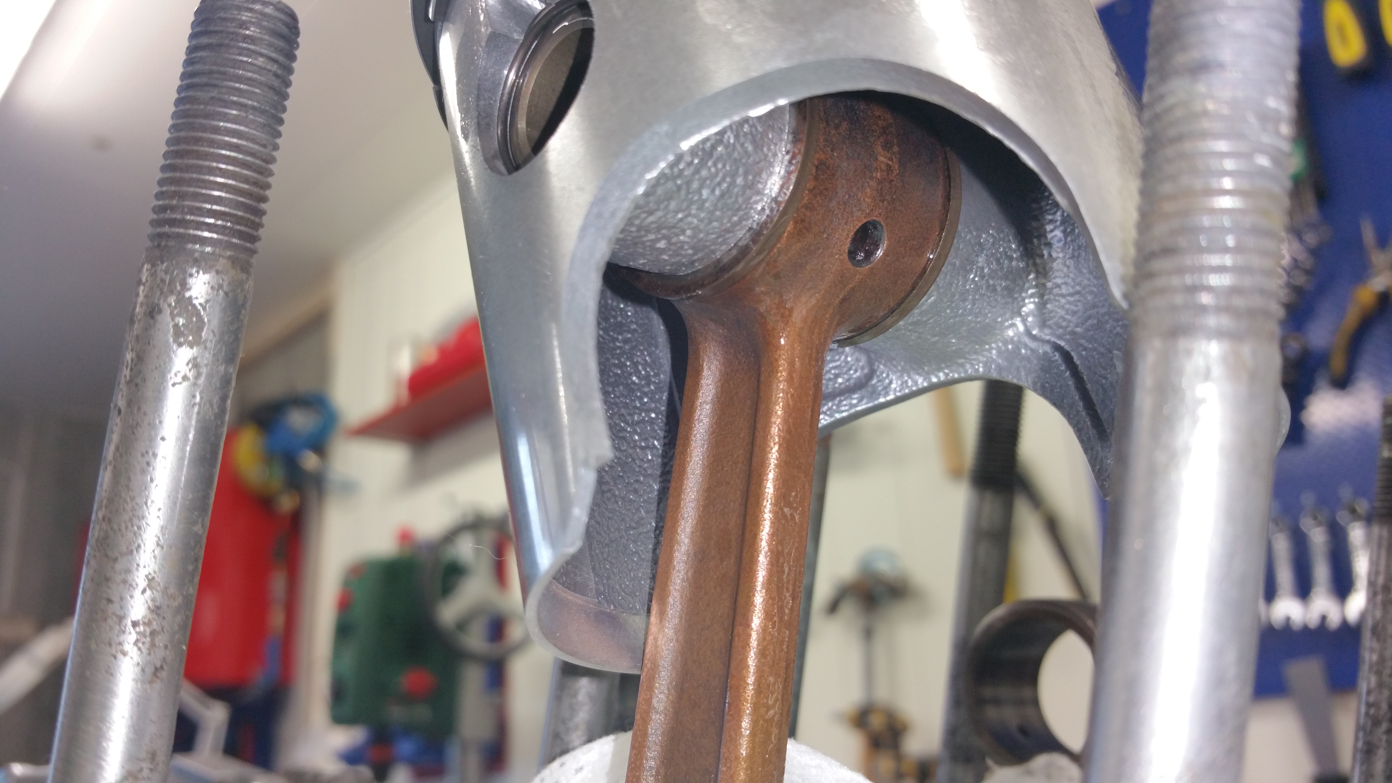
Push in the piston pin and mount the last circlip at the end.
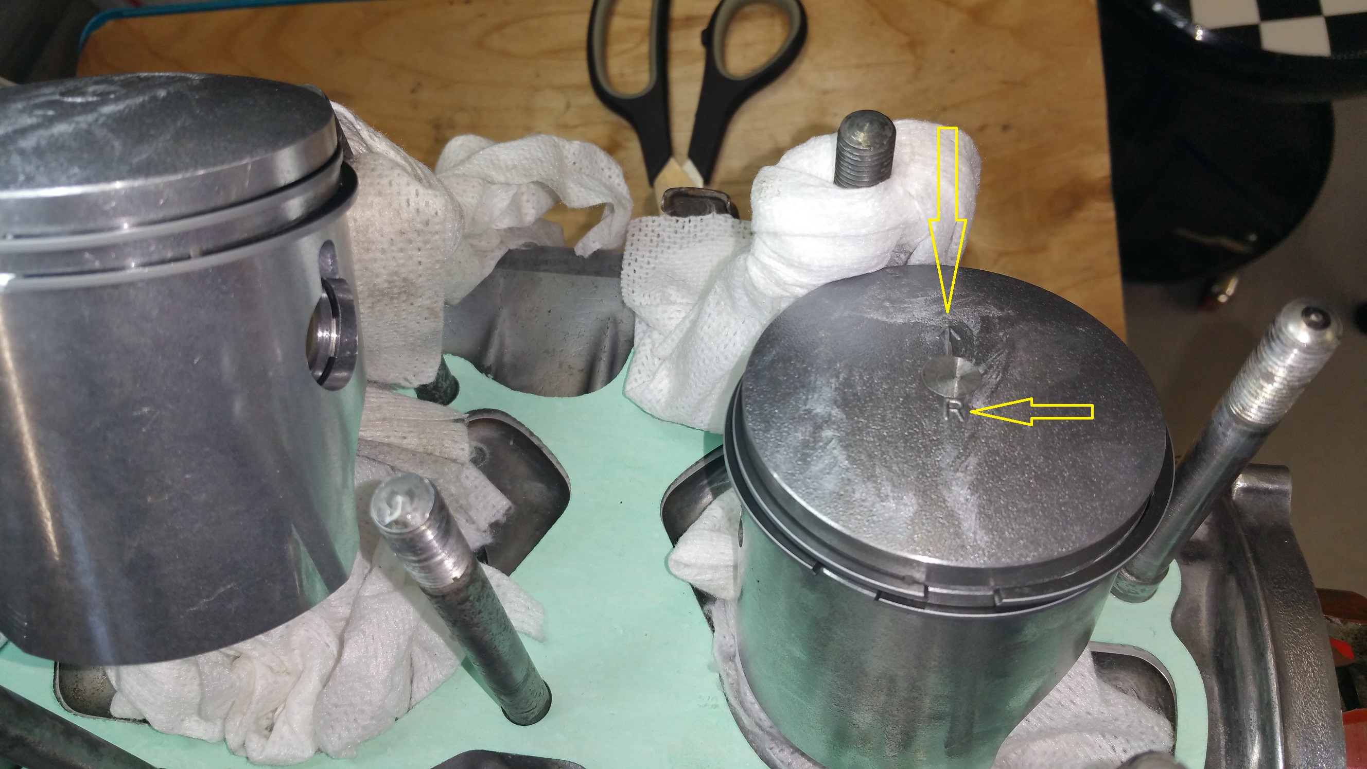
Make sure the right piston (label R) is on the right hand side and the arrow is pointing forwards. The left and center piston are identical and are both labeled L

Suzuki don’t use Loctite for thread locking or other special compounds. Only a drop of paint.
Lock the crankcase and torque to about 20Nm.
Next item:
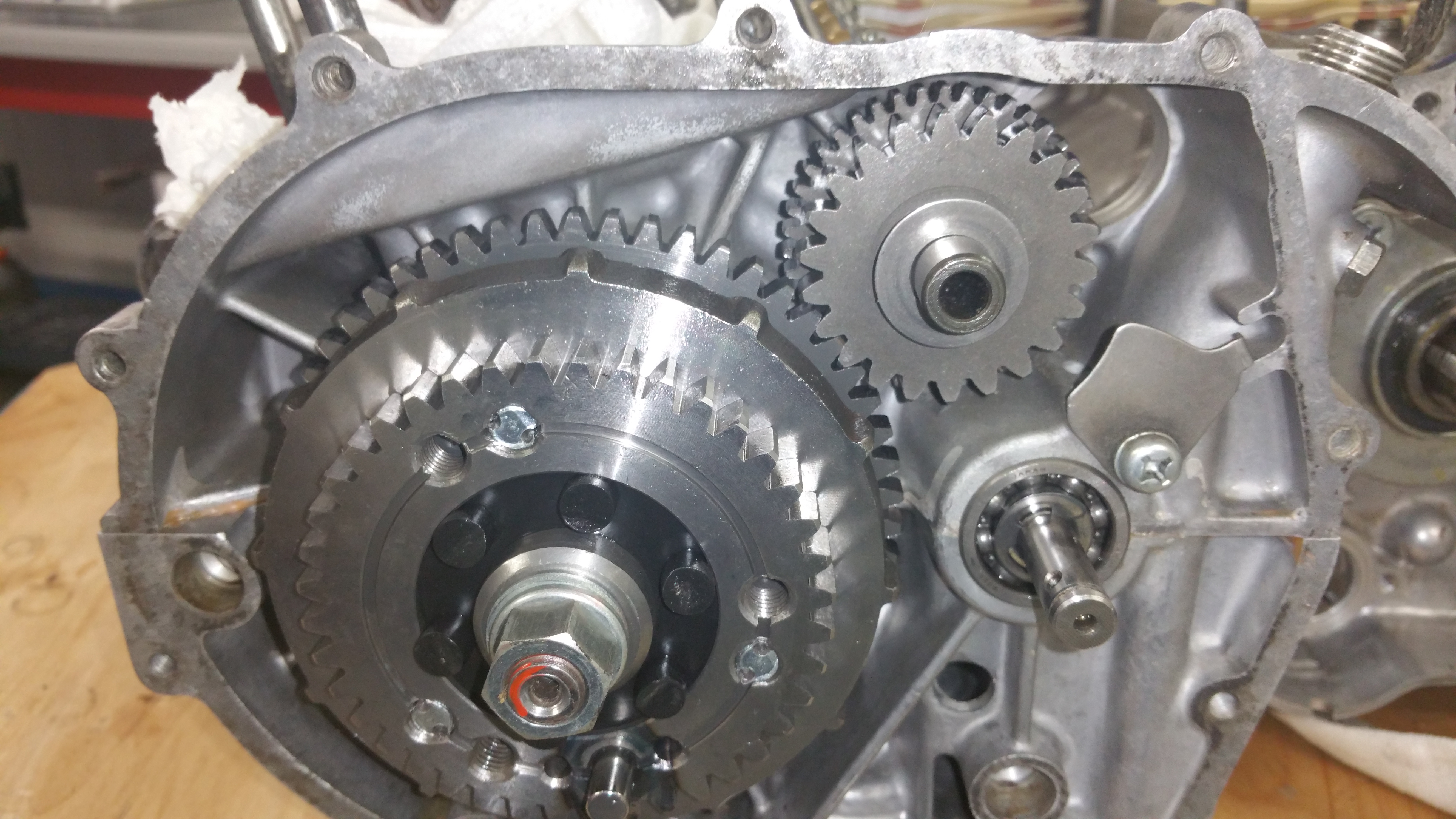
Starter motor:
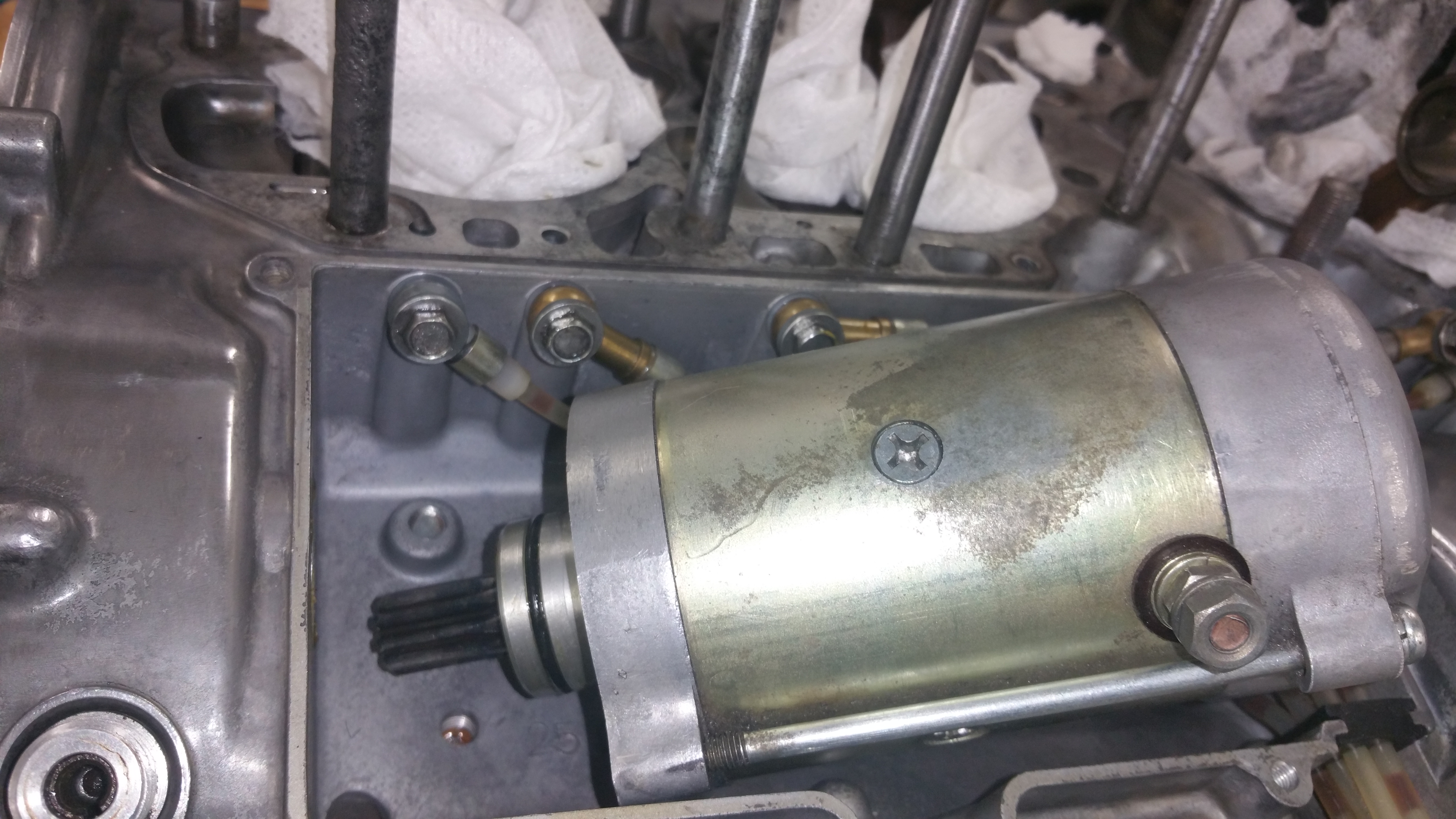
Slide in the motor and mount the screws. Be careful to not damage the oil tubes.
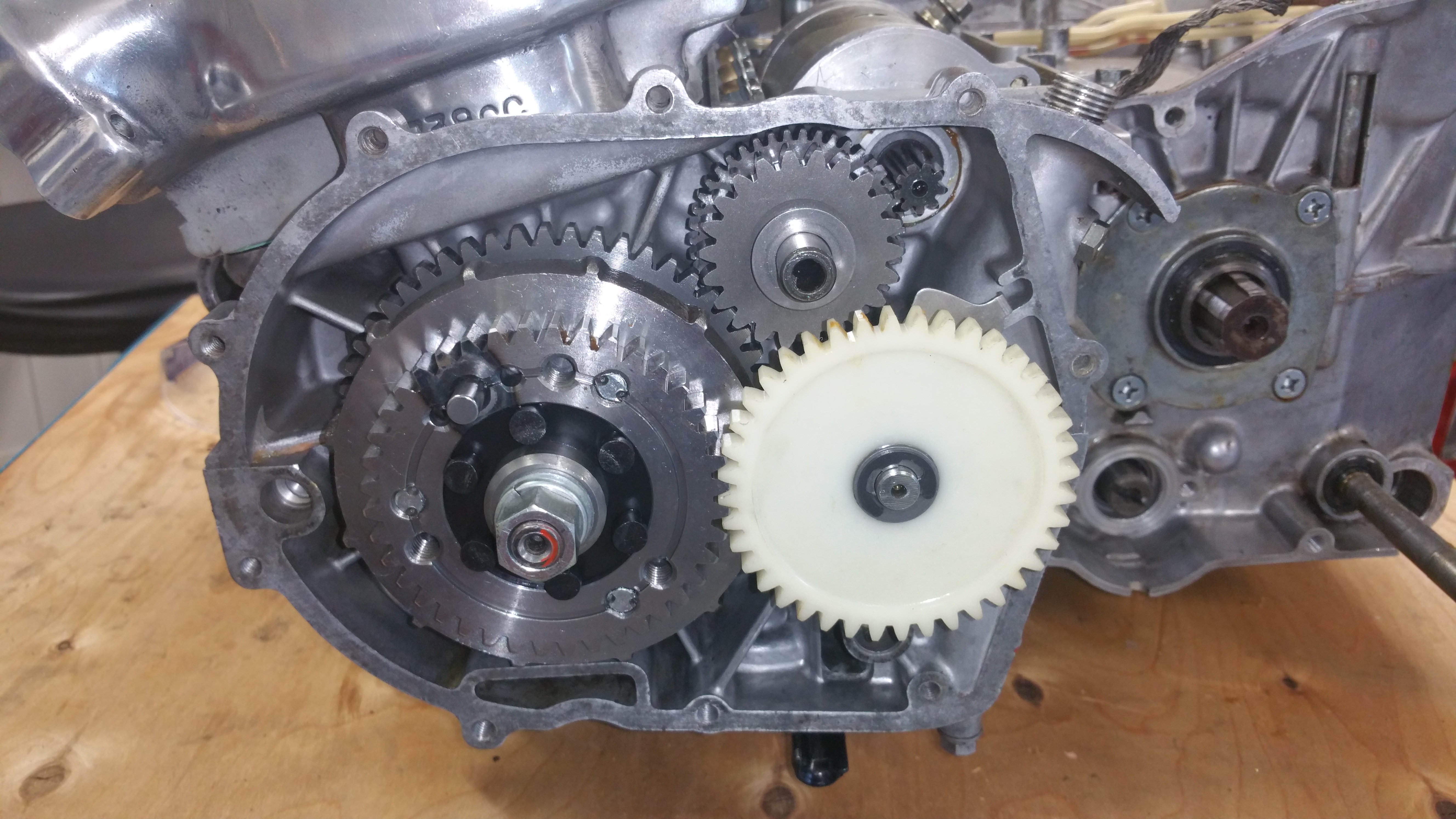
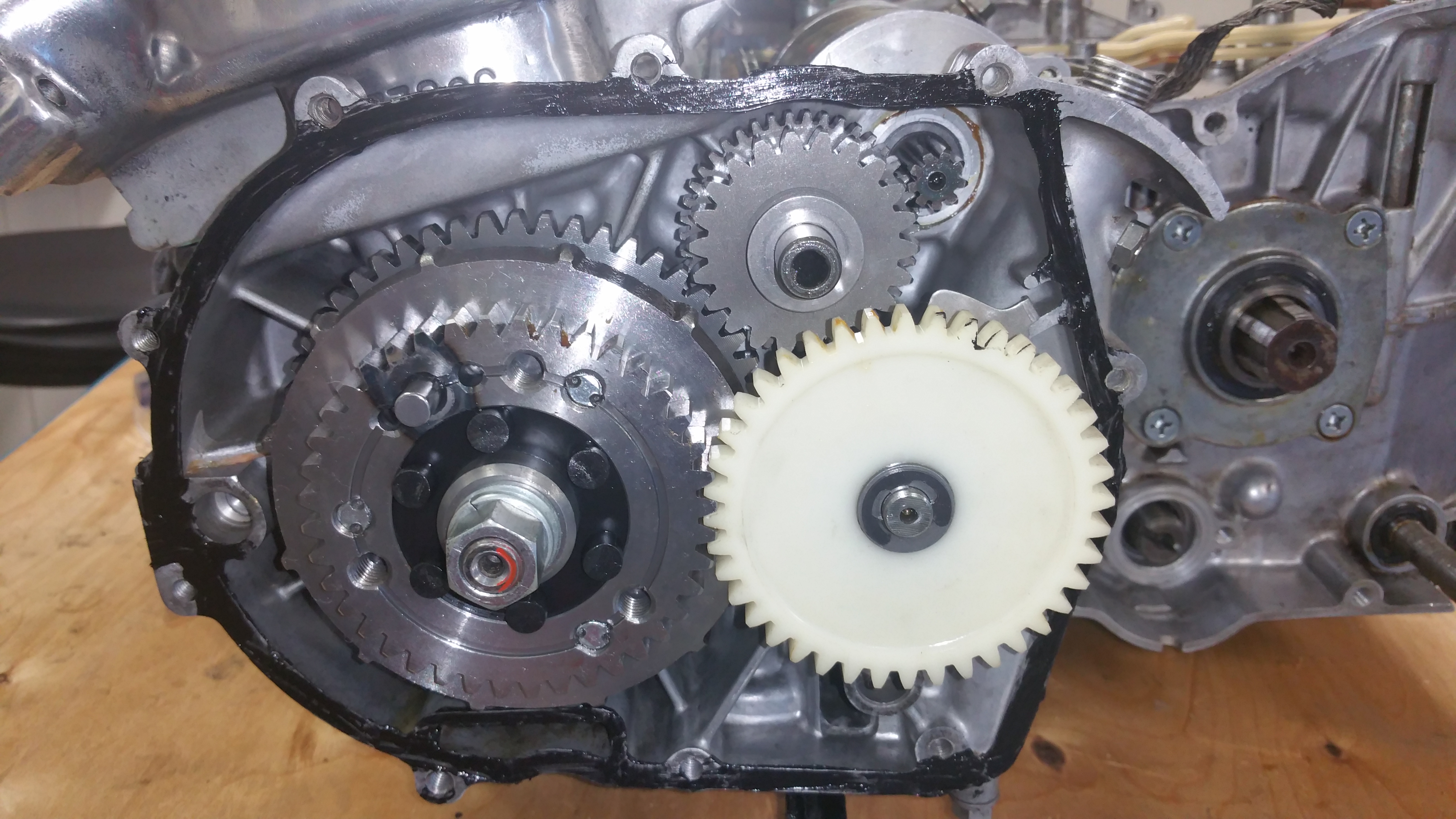
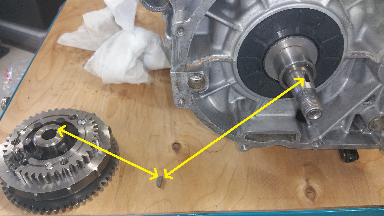
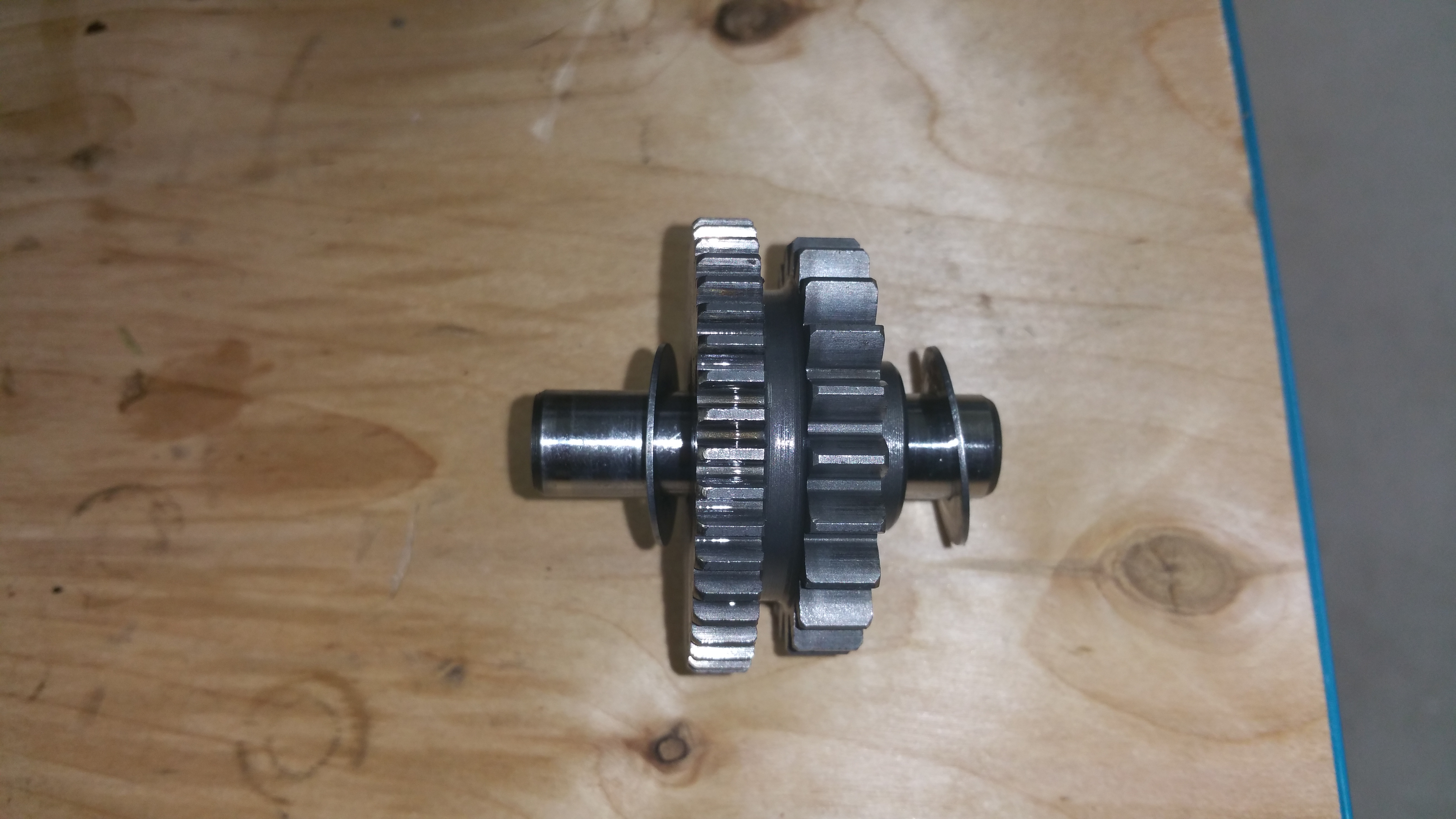
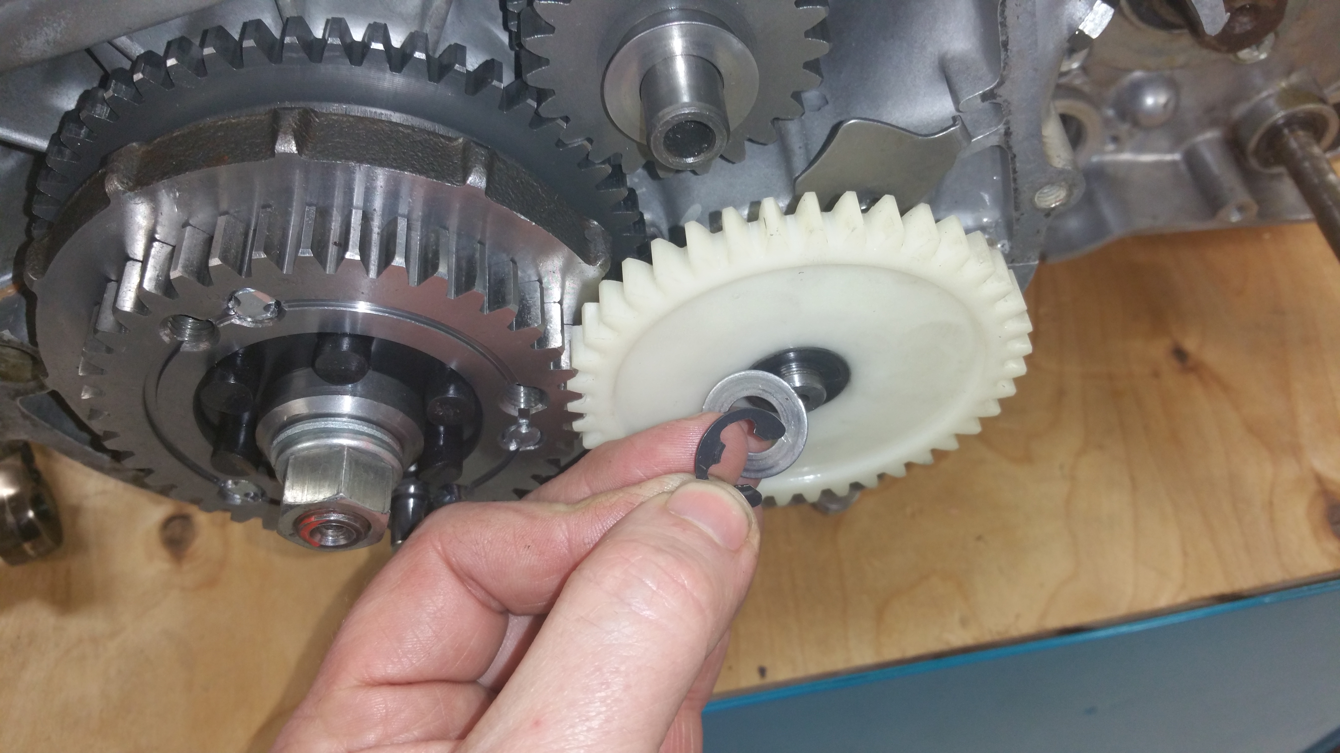
Next step: Install the nylon gear for the water pump

Mounted the rotor part of the generator yesterday + the o-ring and the cover behind the front sprocket

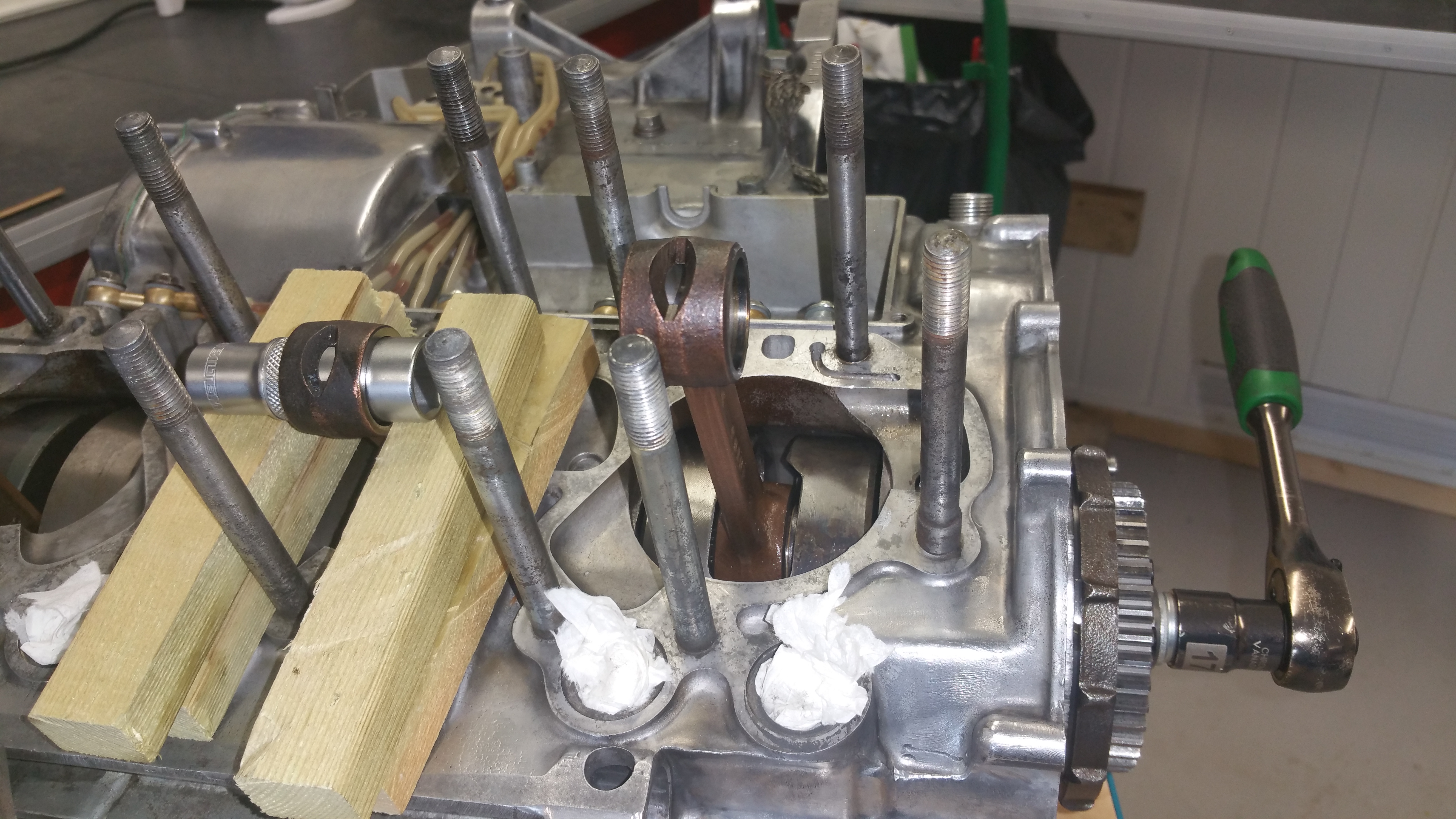
Use some pieces of wood to lock the crank.
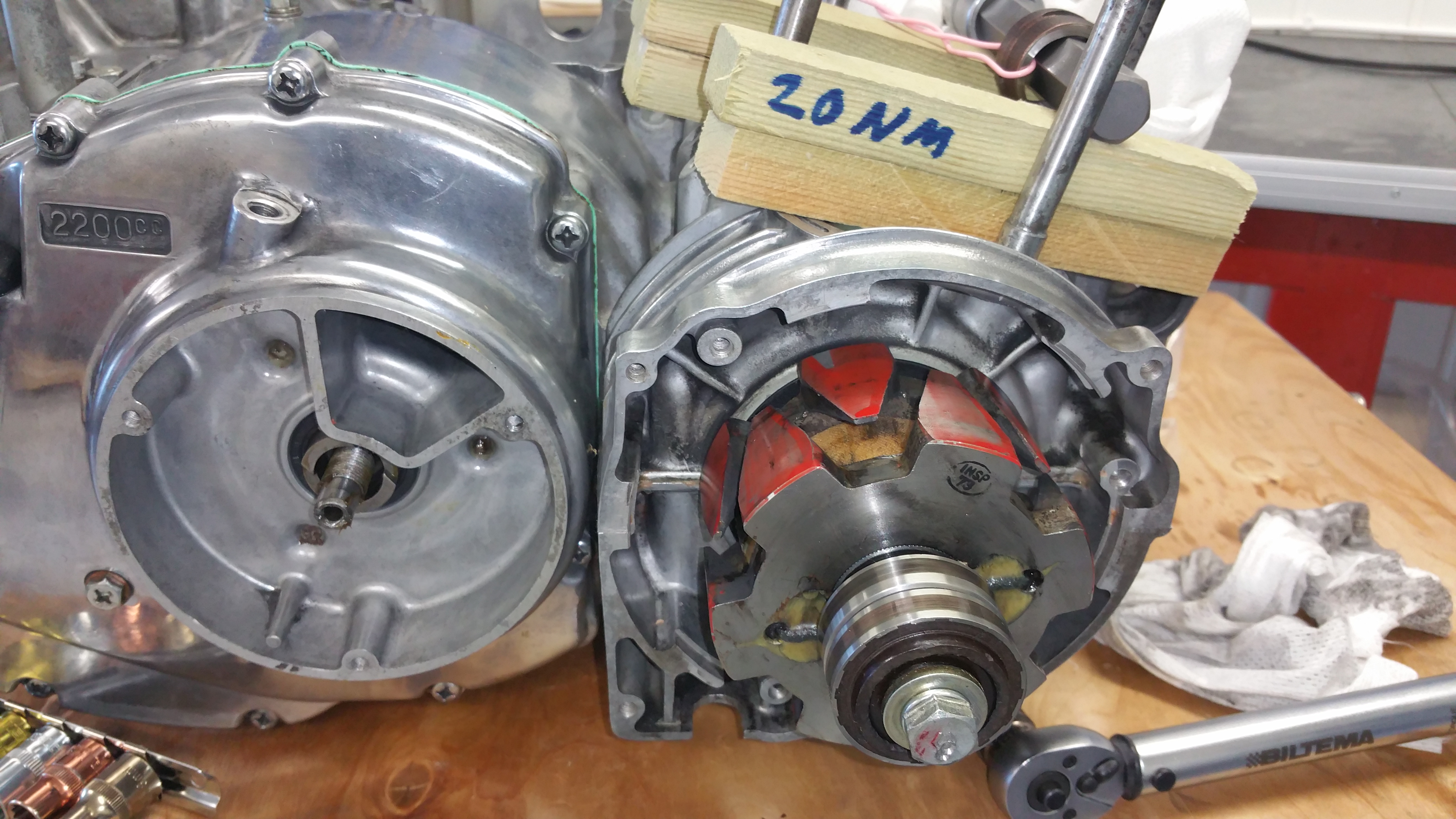
Mount the rotor part of the generator and torque to about 20 Nm
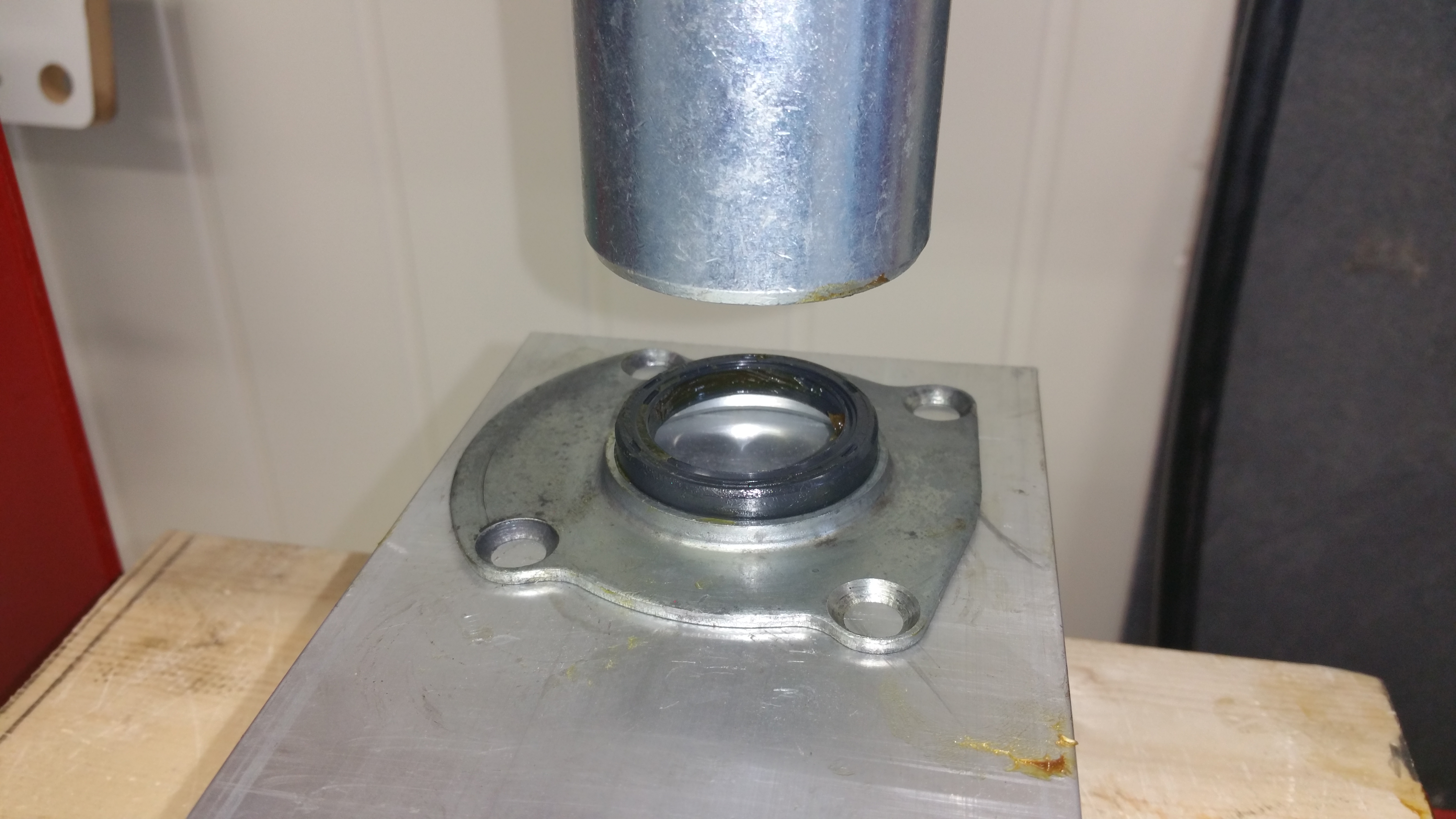
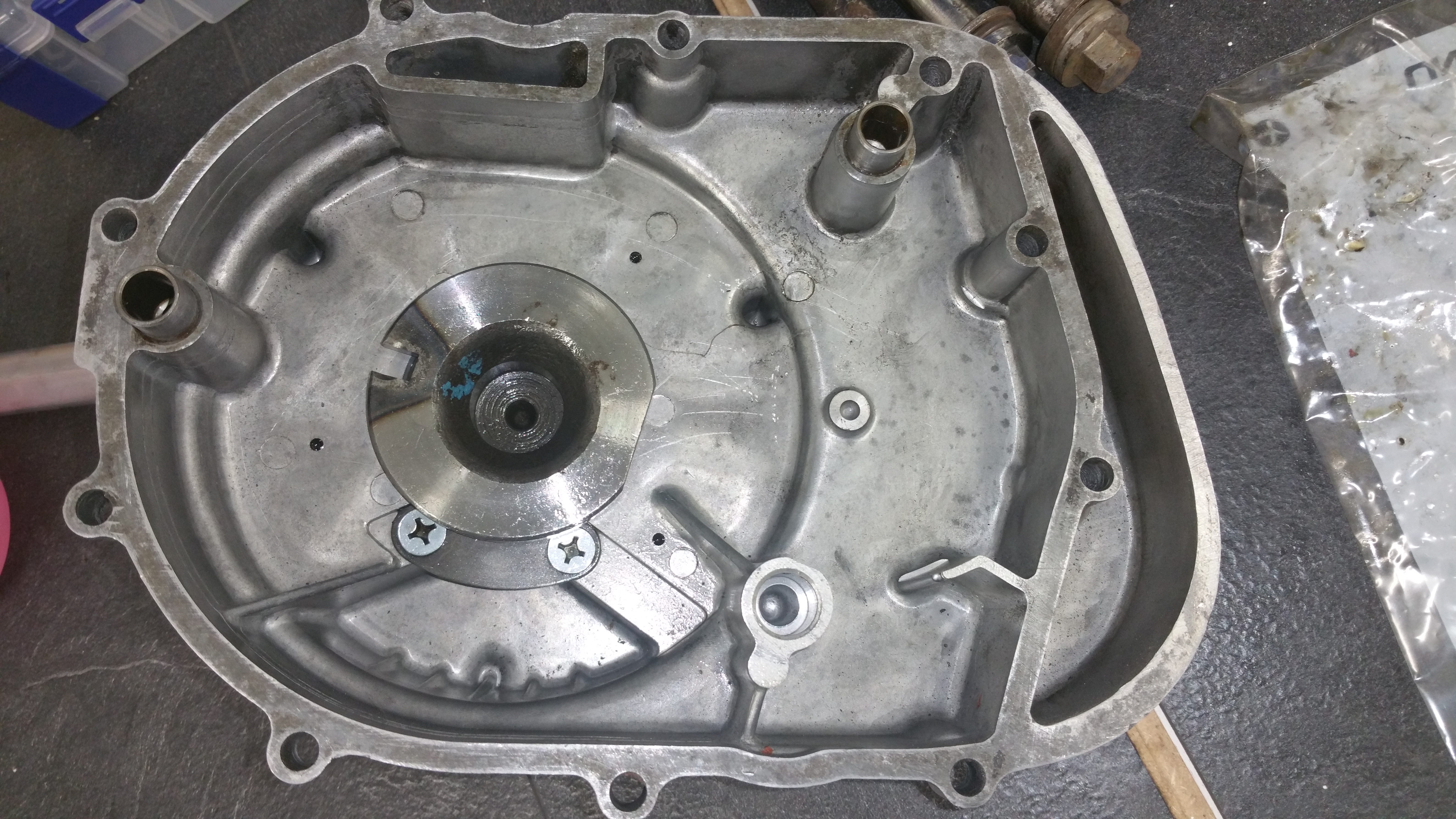
Mounting a new oil seal in the cover behind the front procket.
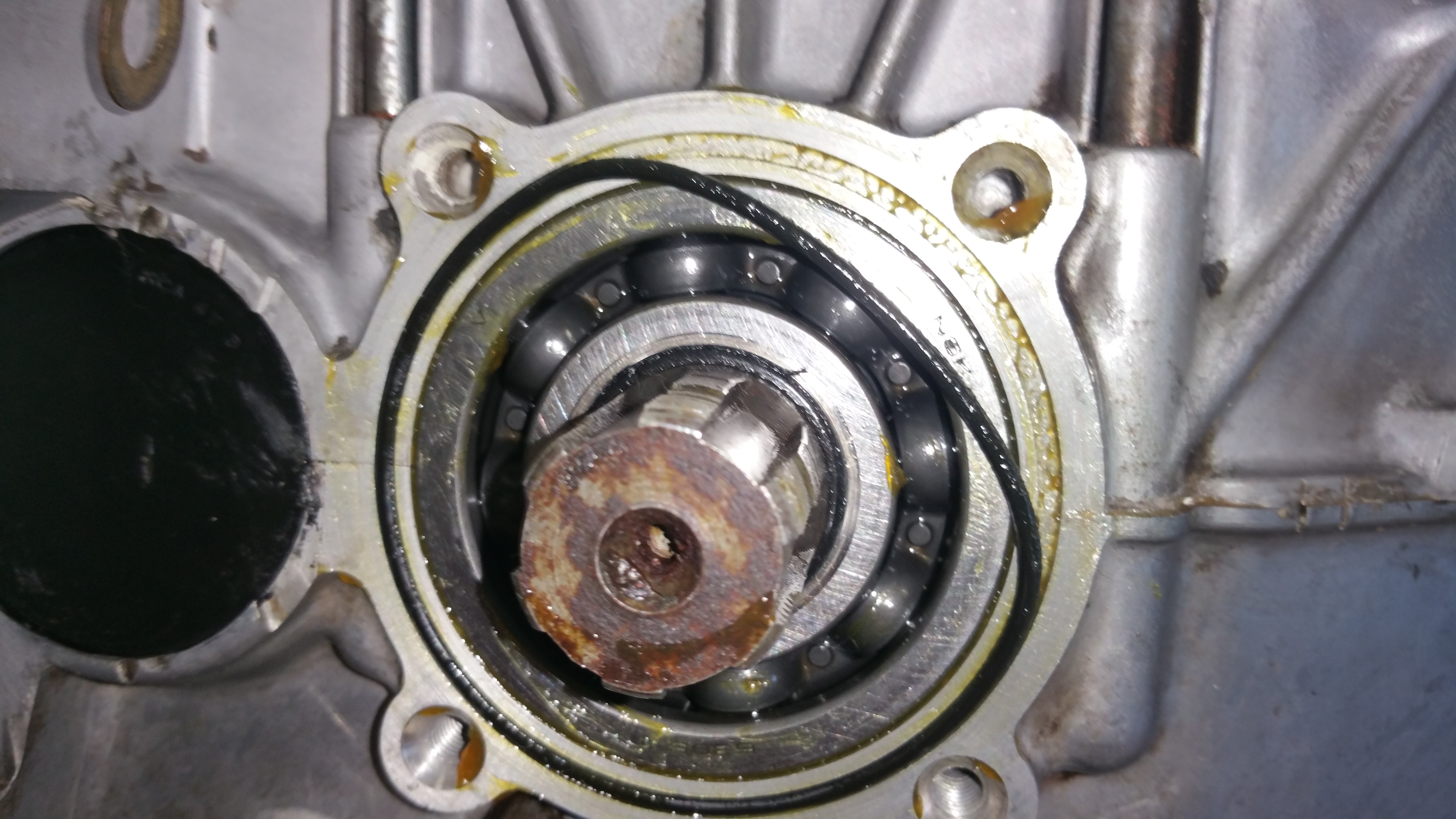
Mounting a new O-ring, use some grease to keep it in place
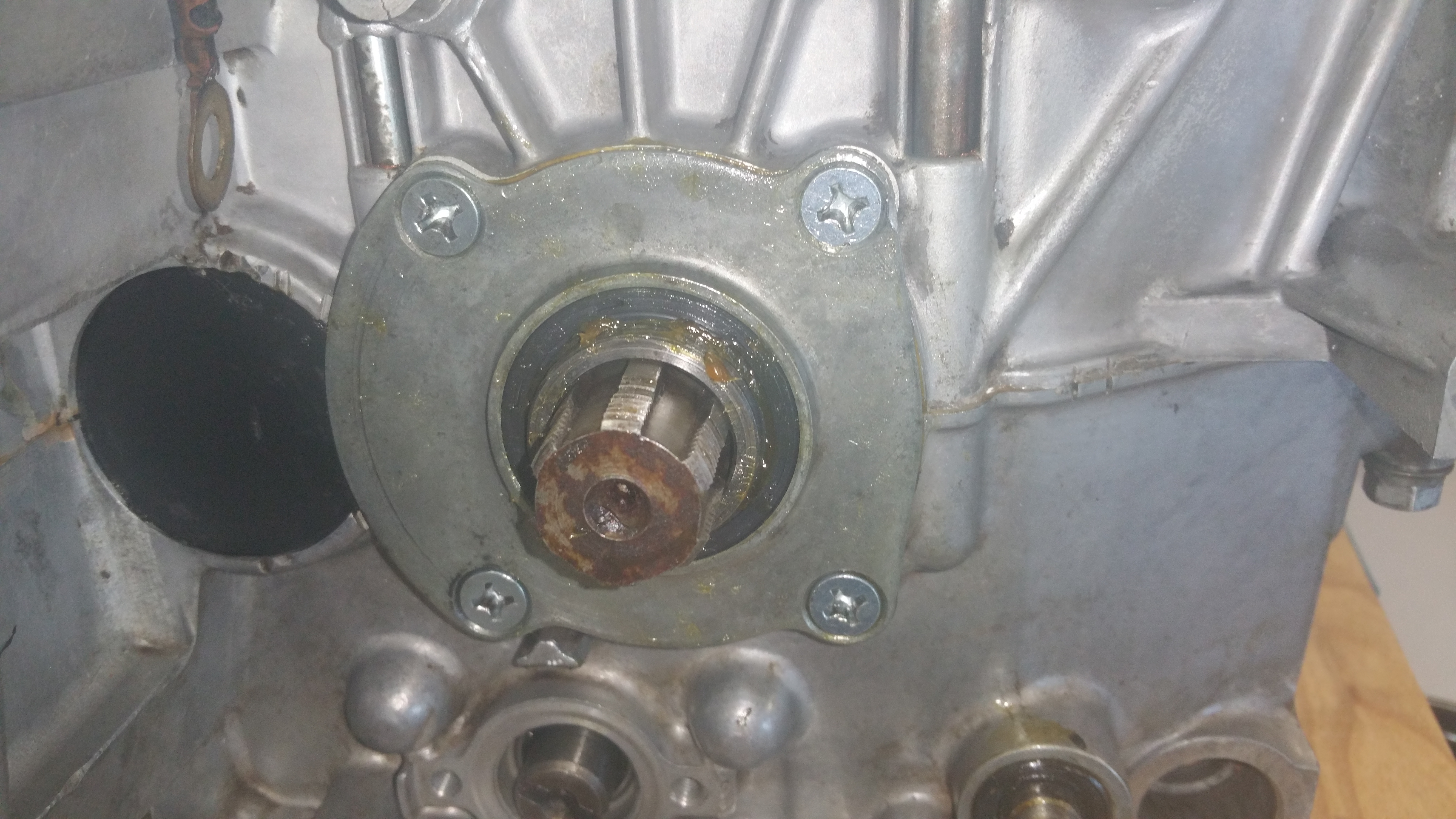
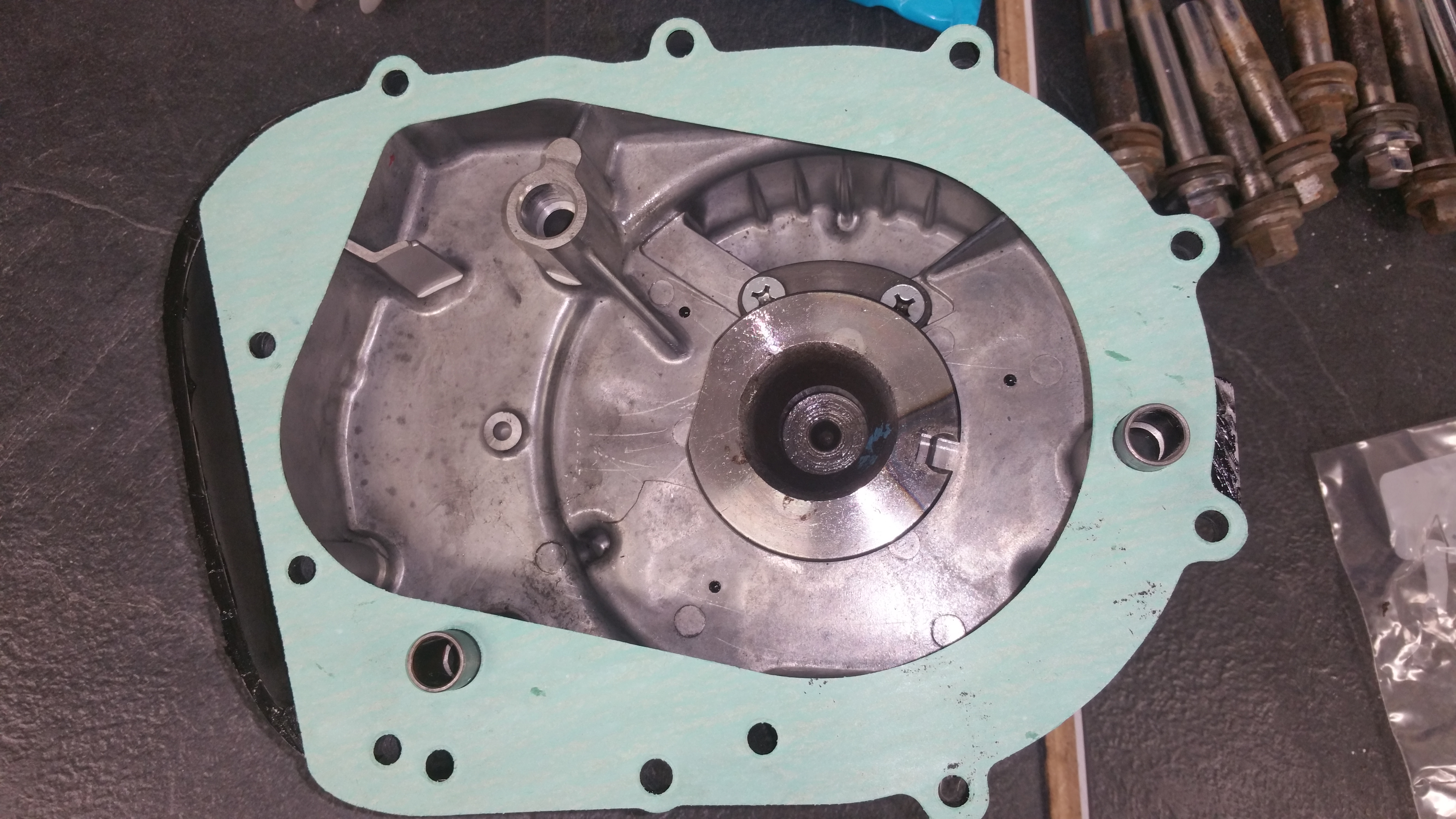
Mounting the cover