Browse Category: Carburetors

Carburetor synchronizing

Sorry for a long time of doing nothing on my blog. Hope to do better in 2022….

I come to mind I did a upload some years ago on YouTube showing an alternative way of synchronizing the carburetors, but I never posted the link on my blog. So, here it is:

The service manual explain how to balance the carburetors, but it can be hard to get it right, and annoying surging will occur at low rpm. Some adjust the butterfly valve looking at the air/light gap holding the carbs up agains a light source, but again, not an easy task.

In the video I pour methylated spirit ( petrol smells too much) into the carburetors and get the time of the drainage. Adjusting the carbs to about the same speed of drainage and the surging is gone at low rpm.
I learned this from Steve in Melbourne, Australia when I visited his sister Donna Ann 5 years ago.

Anti-surge jets

I bought a new carburetor kit last summer and mounted it for a couple of weeks ago. Interesting to compare with the old one I had. The first test run was promising. After a longer ride I got more and more annoyed about the surging at low rpm. Pretty sure it’s more surging compare to the old one. The fuel consumption is better and the color on the spark plugs looks also better while using this kit. If I can get rid of the surging I will keep them on the bike.
The new carb kit has no anti-surge jets mounted. The previous owner said they are all tapped and ready to be fitted with jets.
I don’t have a new jet-kit, but I have a lathe and milling machine. Let’s make a set of three 0,8mm jets.

Bulletins no 36 explain how it’s mounted :http://www.ozebook.com/compendium/techbuls/index.htm

Jet fitted:

Please read the application note no 36 and follow the procedure how use the 4mm tap.

Test ride:

Very pleased with the test run. The annoying surging issue was gone. 🙂

Service Bulletin GT-36

Butterfly shaft repair

While doing the work on the carburetors I saw two of the butterfly shafts had bad threads for the 3mm screw holding the butterfly valve.

The one on the photo below looks like it has a previous repair using some sort of insert, not sure but it looks bad.

Click on the images for detailed view

The procedure below is a much better way to do the repair. Since the shaft is made of brass a new piece of brass can easily be soldered into the bad area.


Drill down about 1,5 mm using a 6mm drill bit.


Continue down to 2,5mm using an end mill. ( not all the way through )


The piece of brass has been soldered


Use a lathe to turn turn off the brass piece until the shaft looks smooth and nice.


Use the second hole as alignment to get the right angle before you drill out the new part using a 2,5mm drill bit.


Make new 3mm threads and you are done. Good luck 🙂


Mounted back into the carburetor

Left butterfly valve assembly

As always, click on the images for detailed view.

Step 1

Add some grease on the both ends of the shaft.

Very much the same assembly as on the right carb ( see the post Right butterfly vavle assembly )


Step 2

Insert the seal with the lips facing outwards. Two seals, one for each end.


Step 3

Insert the shaft and the butterfly valve. Secure the screws with loctite. Use new screws if they are worn.

Note, the text on the valve facing upwards (red arrow on the picture )

Make sure the valve sits well and is the correct position. If not you will get trouble later on doing the synchronization ( balancing ) of the carbs.


Step 4


Step 5

Most of the parts got some seconds or minutes on the polishing machine before mounting, the spring as well. Looks so much better.


Step 6


Step 7


Step 8

DONE !


Carburetor Top

Parts to be mounted in the carb top.

Click on images for detailed view.

The normal position of the circlip should be in the middle, not like the one on the picture.  Adjustment can be done to get a better temperature on the spark plug.  Do not change the original needle with an aftermarket one if  the original is OK and not worn.

You can check the tension and length of the spring according to the service manual. It’s more important to check that all three spring has the same length. That will be important later on when you are doing the syncronization of the carbs.

Step 1

Use a flashlight and check the diaphragm for any leakages

HELP ! I found a hole. Have to get a new one….@#%%@@

Step 2

Get a new one and proceed.

Install the needle

Step 3

Install the cap ( needle plate )

Step 4

Add grease to give a tight seal against the diaphragm


Step 5

Install the diaphragm , note the position shown by the arrow.


Step 6

Mount the spring and the top cover.


Step 7

Test the diaphragm by pushing the piston up and hold you finger above the intake hole.

The piston should stay stable, or move very slow.  Release our finger and the piston shall go down.

Step 8

Done 🙂

Float chamber assembly

Float chamber

Click on the images for detailed view.

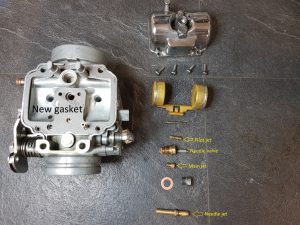
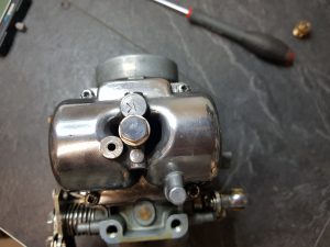
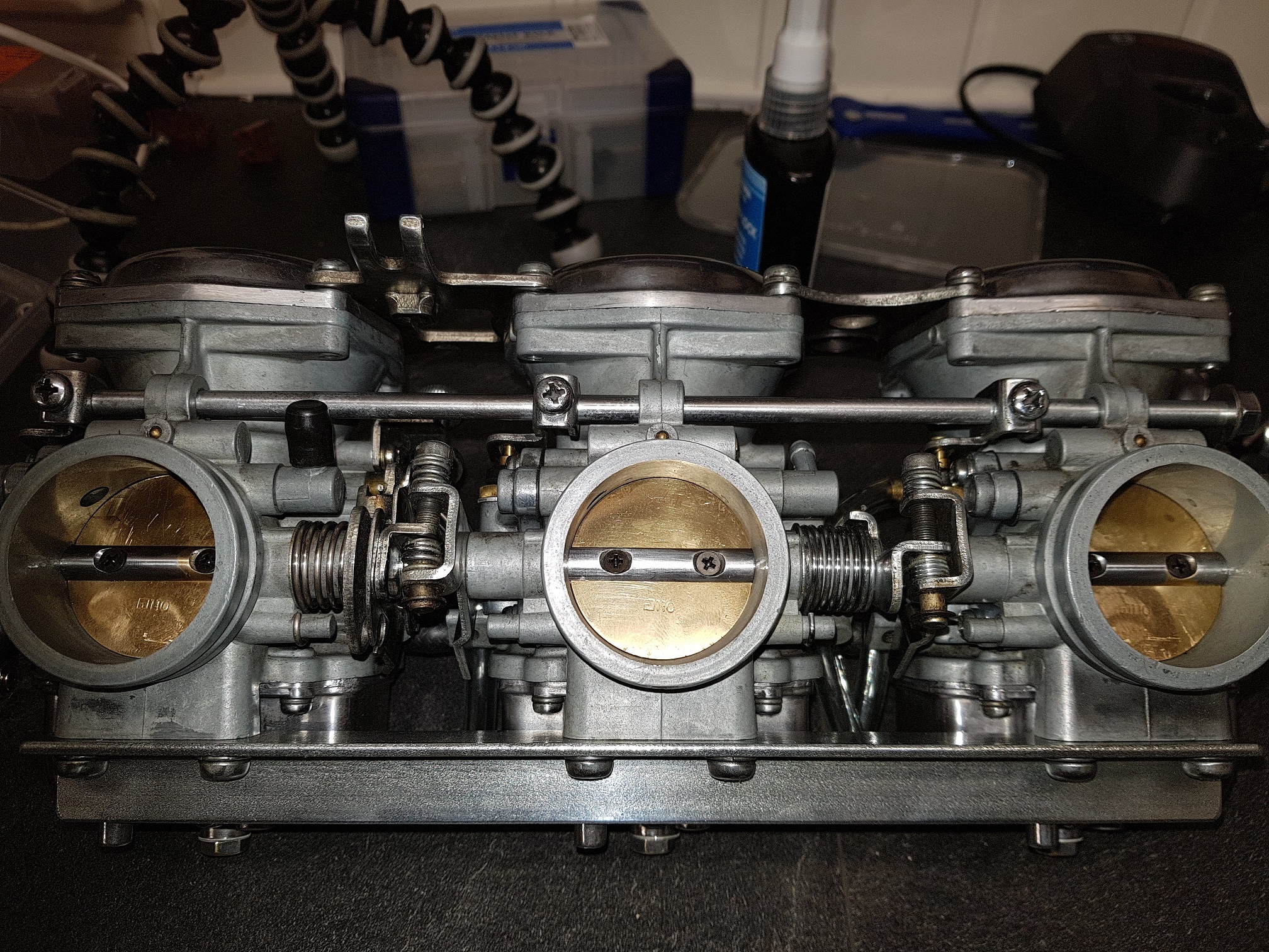
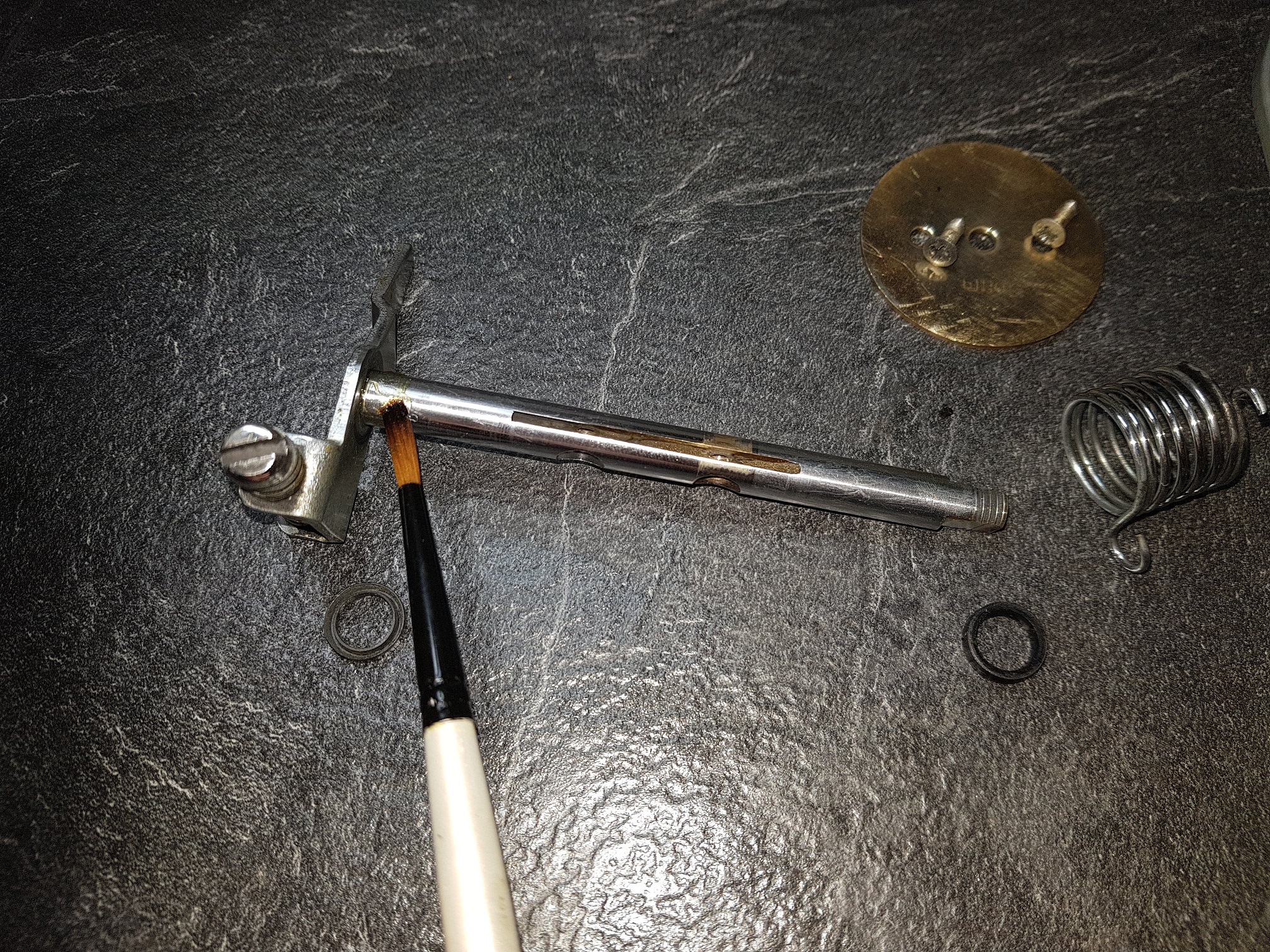
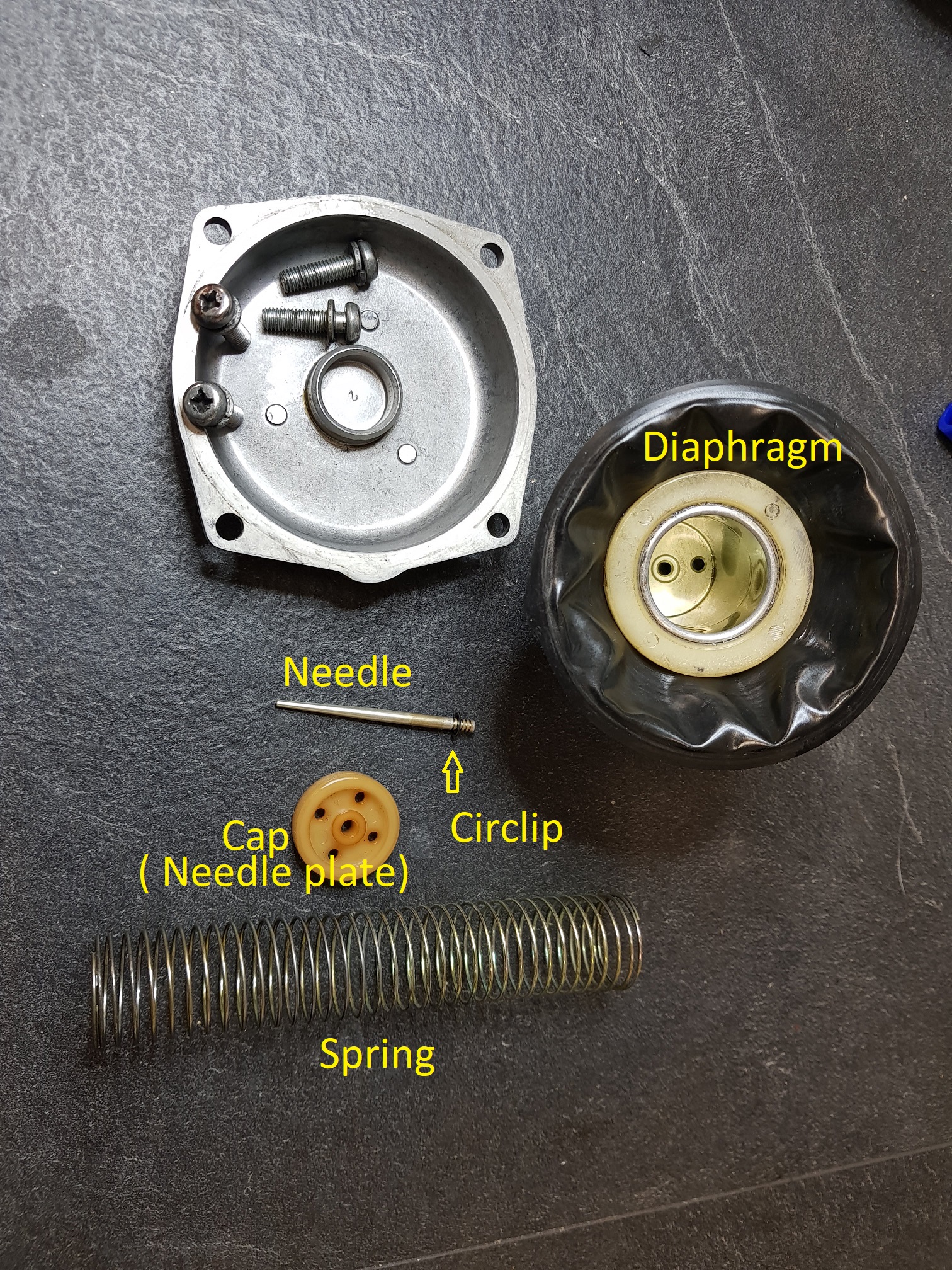
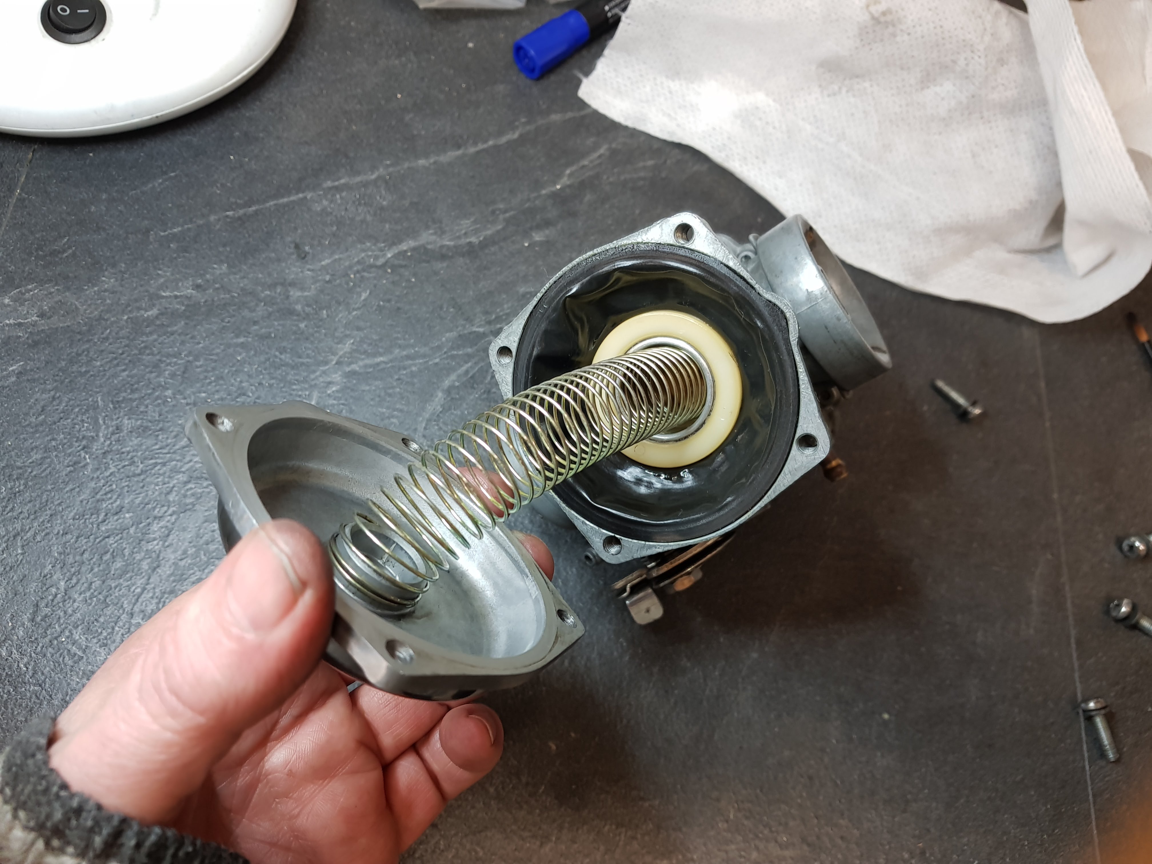
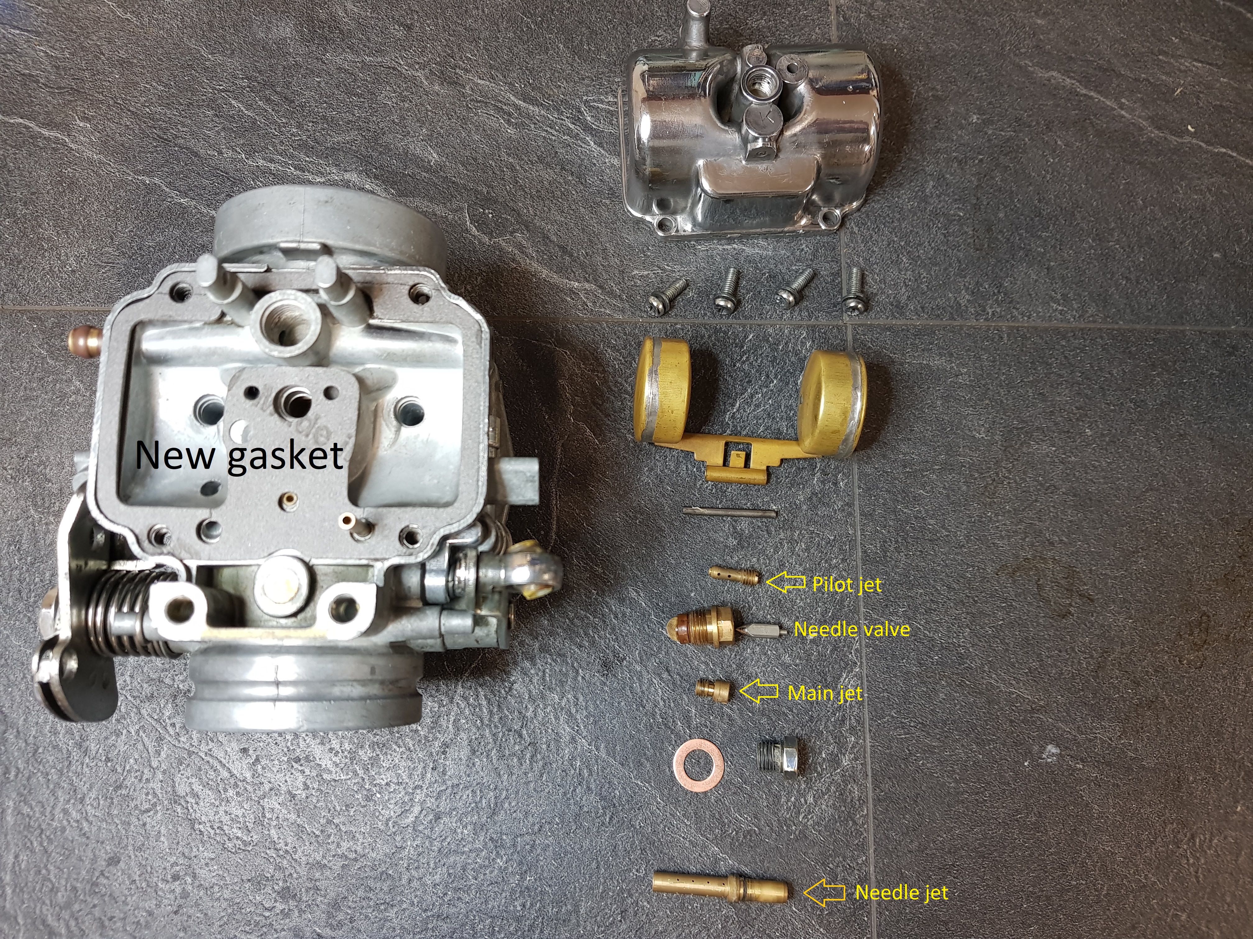
The picture above shows all the part in the float chamber
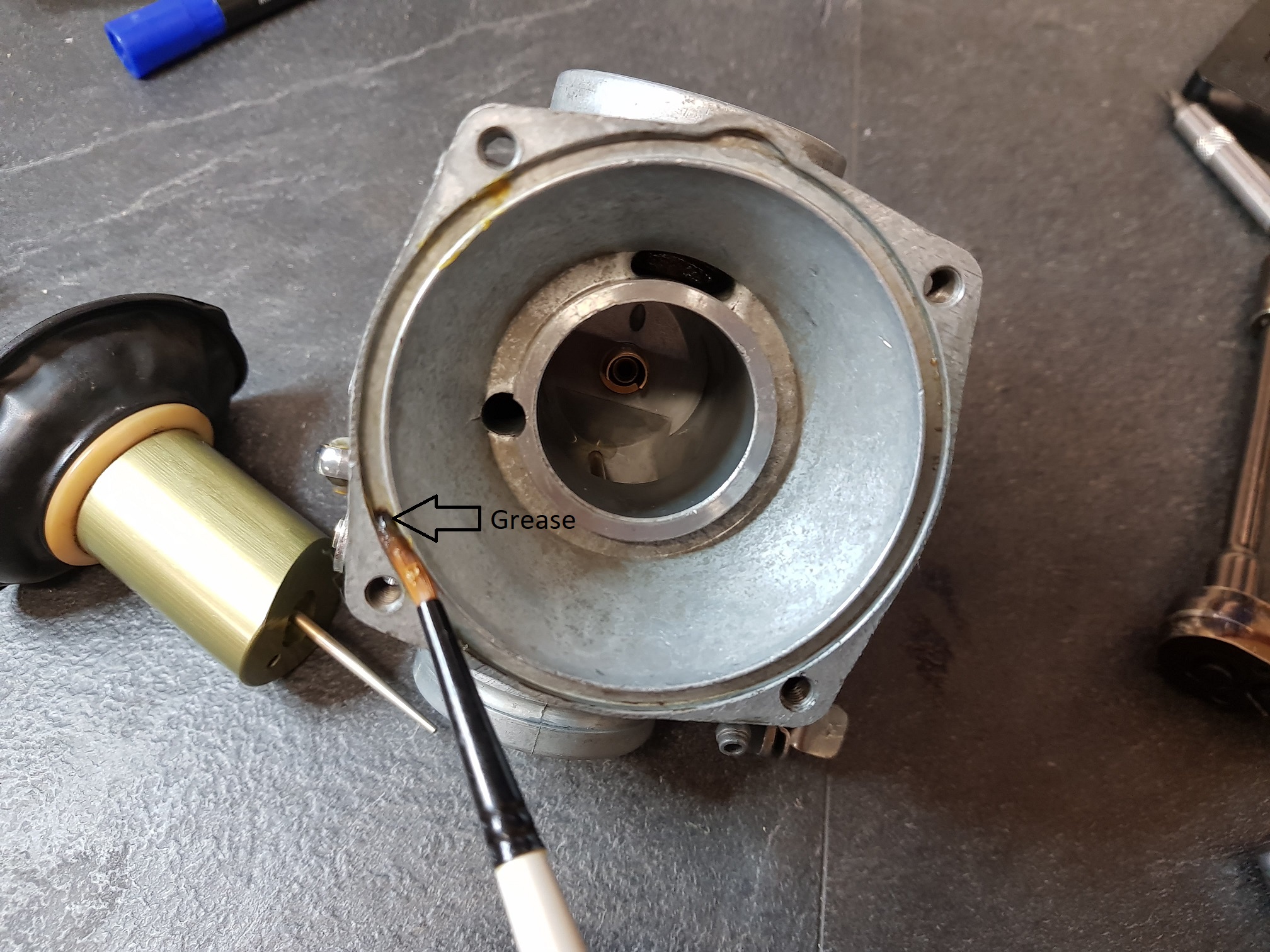
 

Step 1 

Install a new gasket. Some of the aftermarket kit might require some trimming of the gasket. If the original gasket is an a good shape, keep it and don’t replace it.

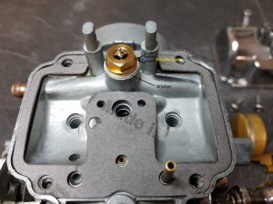
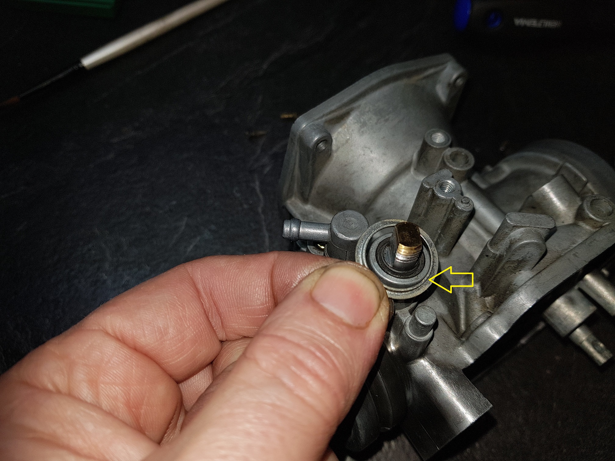
Install the needle valve. Don’t forget the washer.

Step 2

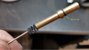
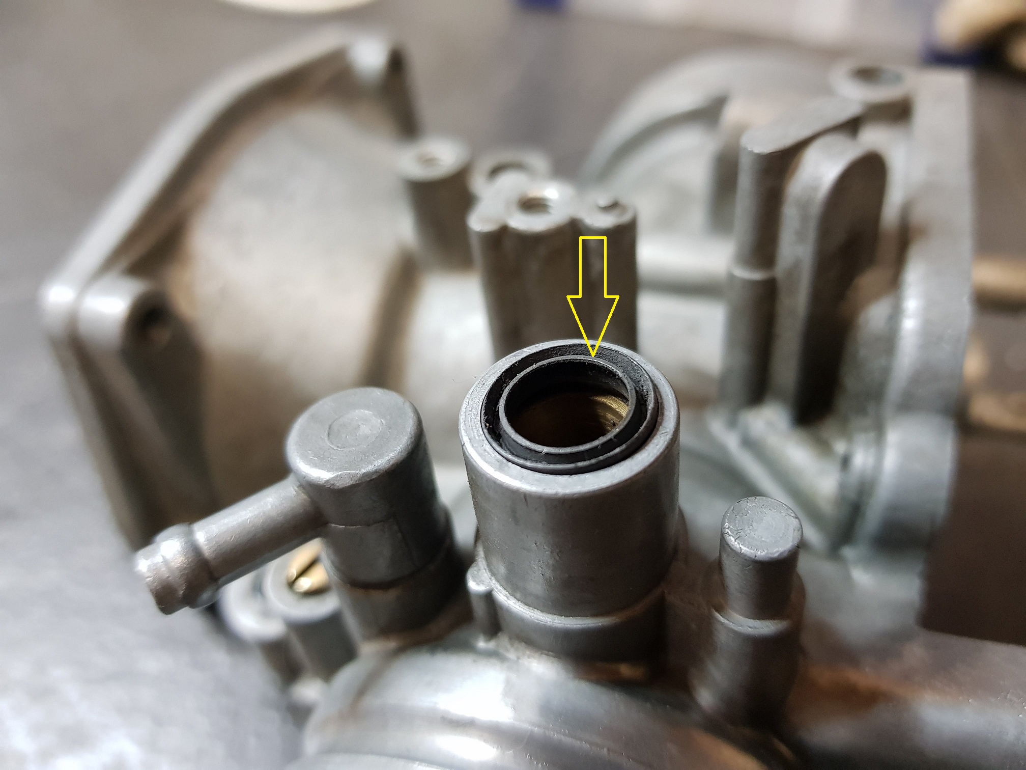
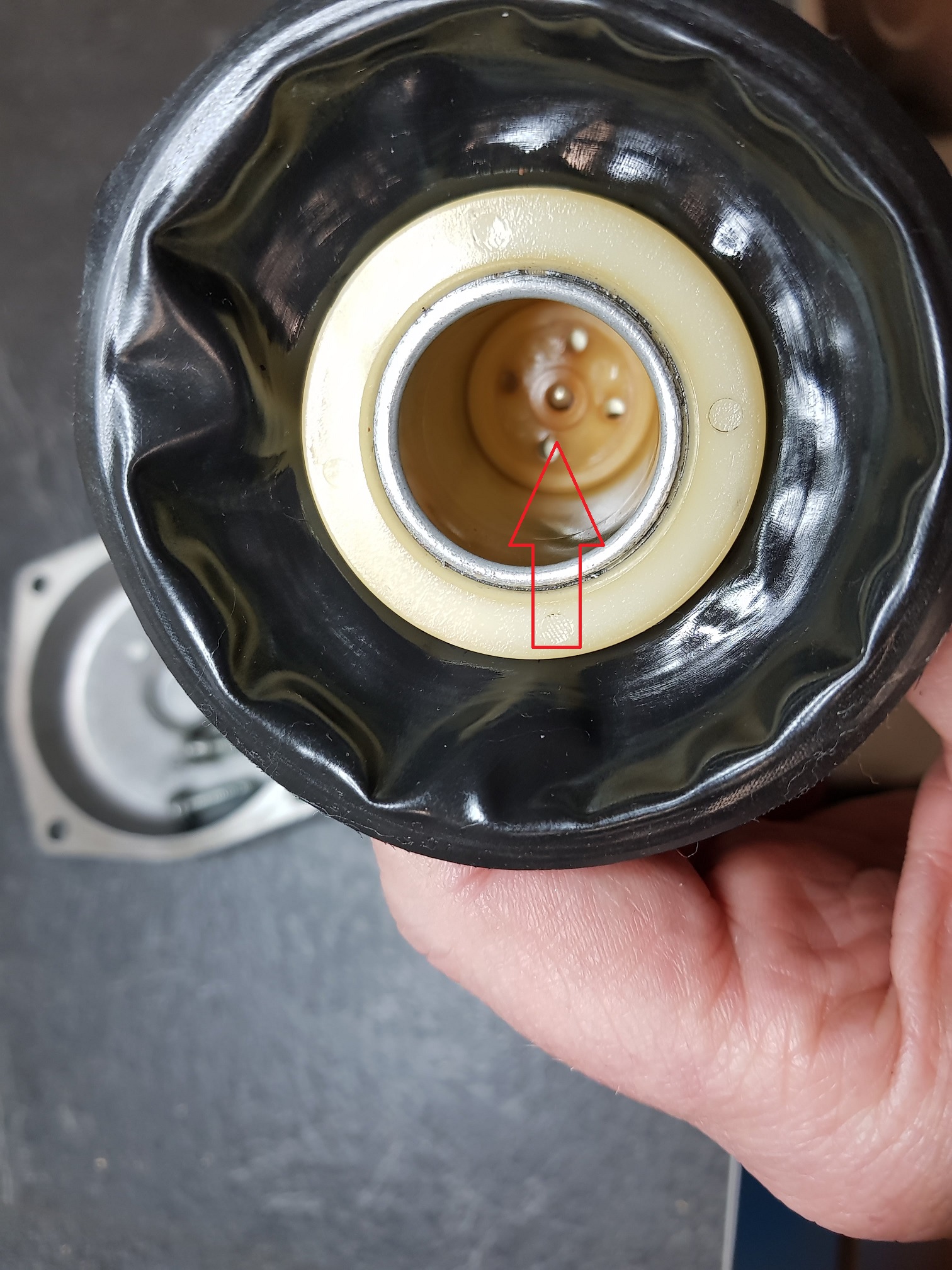
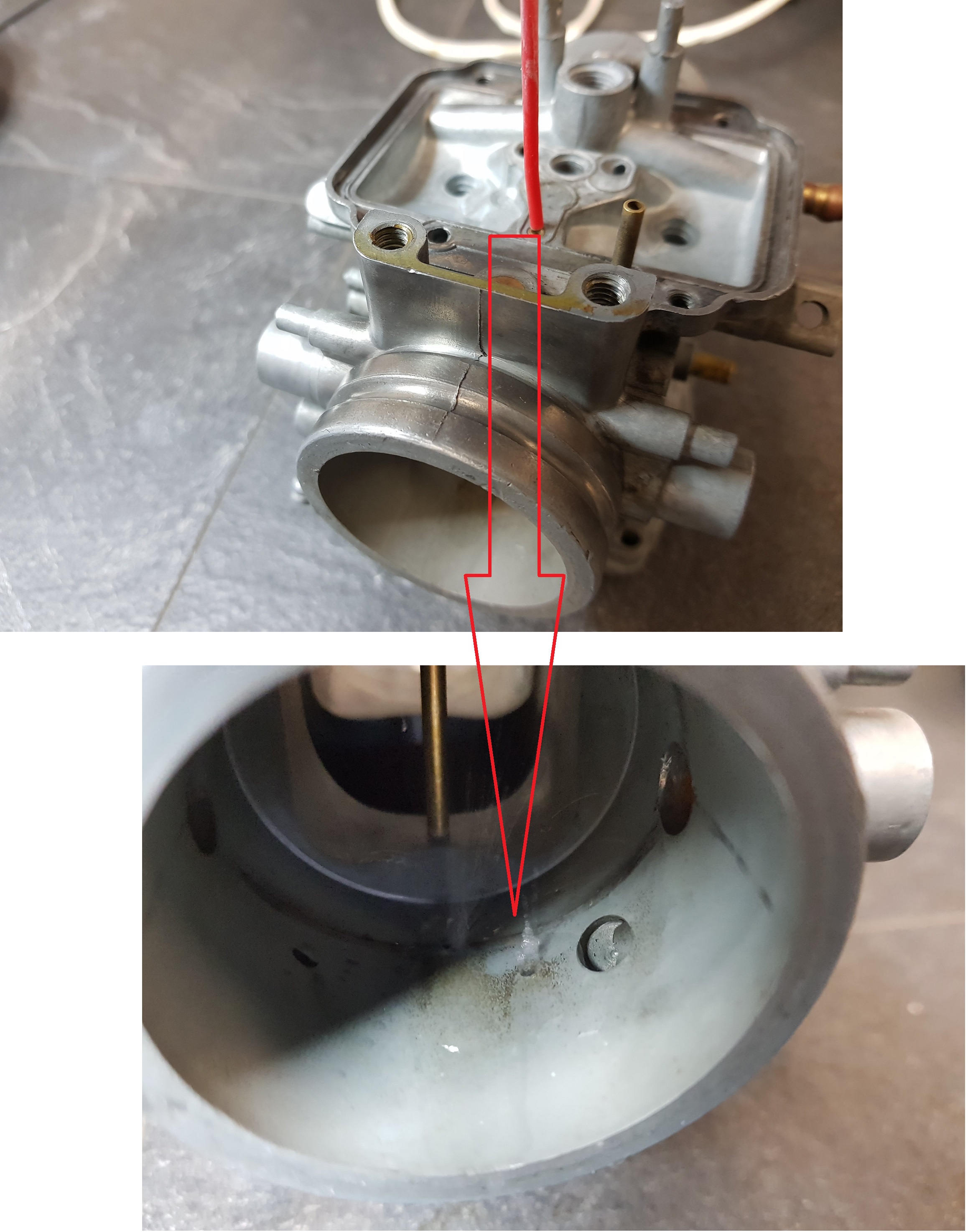
Clean the needle jet before mounting using brush, carb cleaner and compressed air.
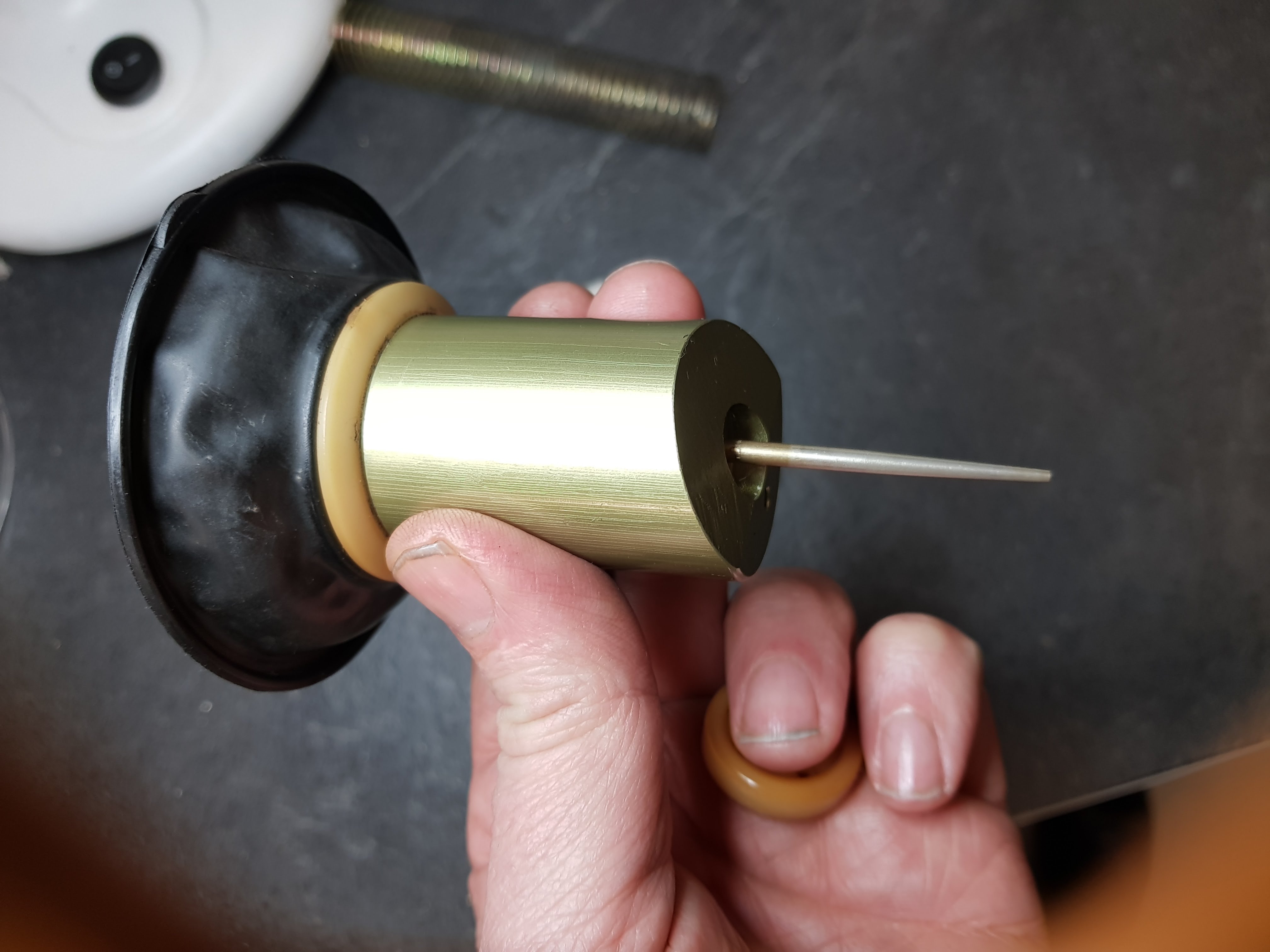
Replace the O-ring.


Step 3


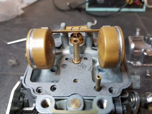
Mount the needle jet and the float.

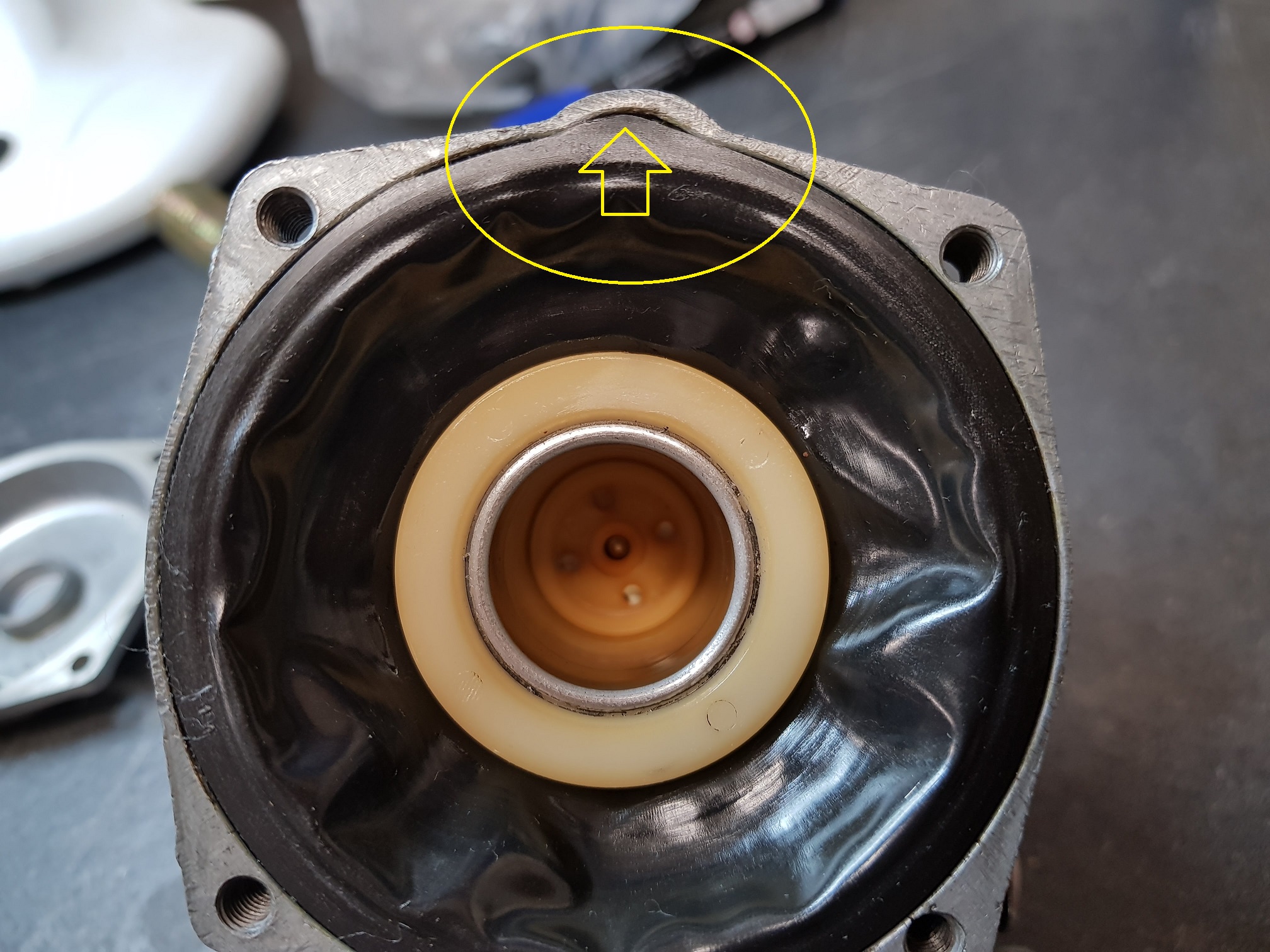
You can easily check the function of the valve by blowing air from you lungs into the fuel inlet and hold one finger on the outlet on the other side. By lifting the float up and down you will sense if the flow turn on and off when the valve is activated.


Step 4

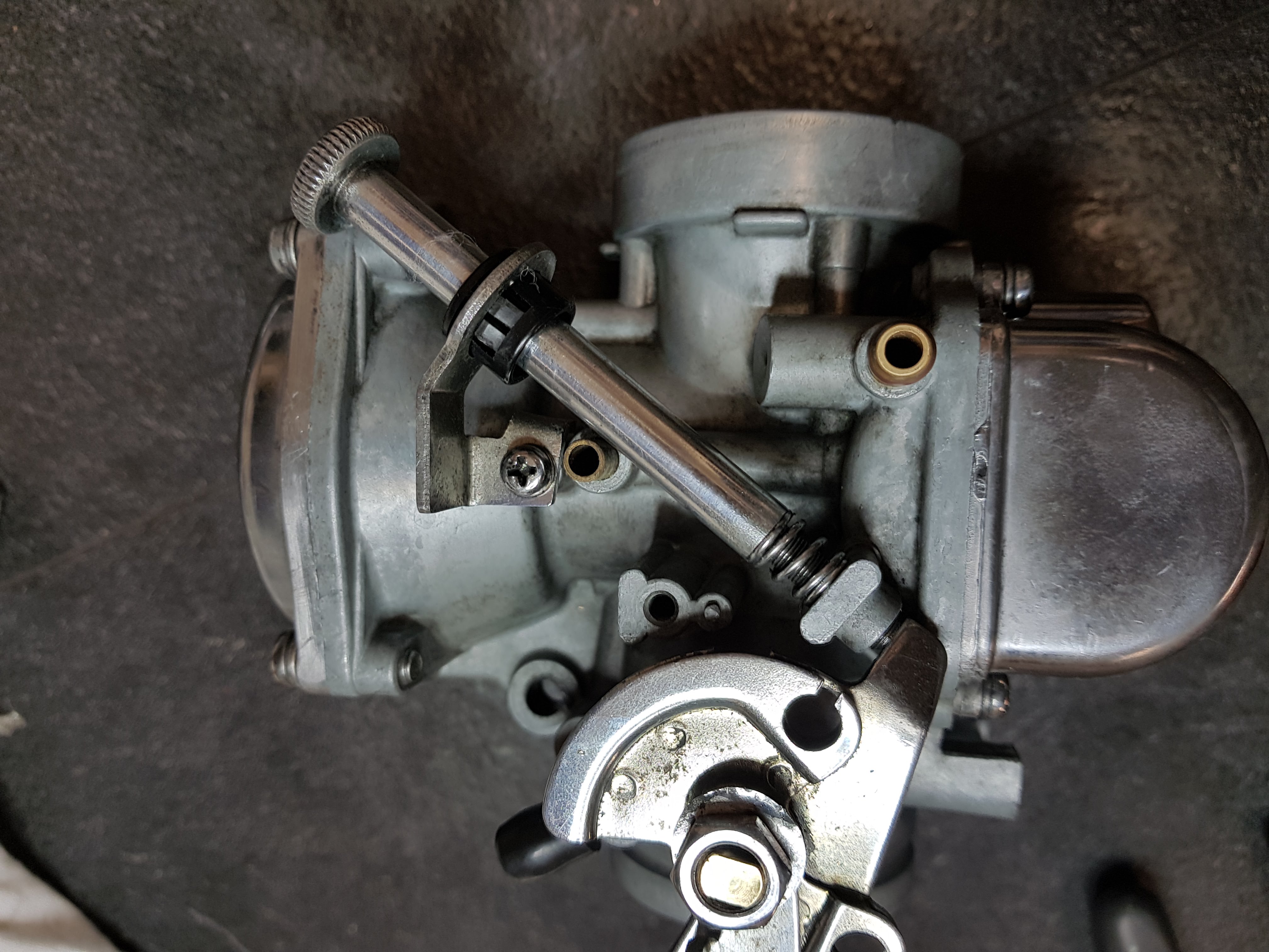
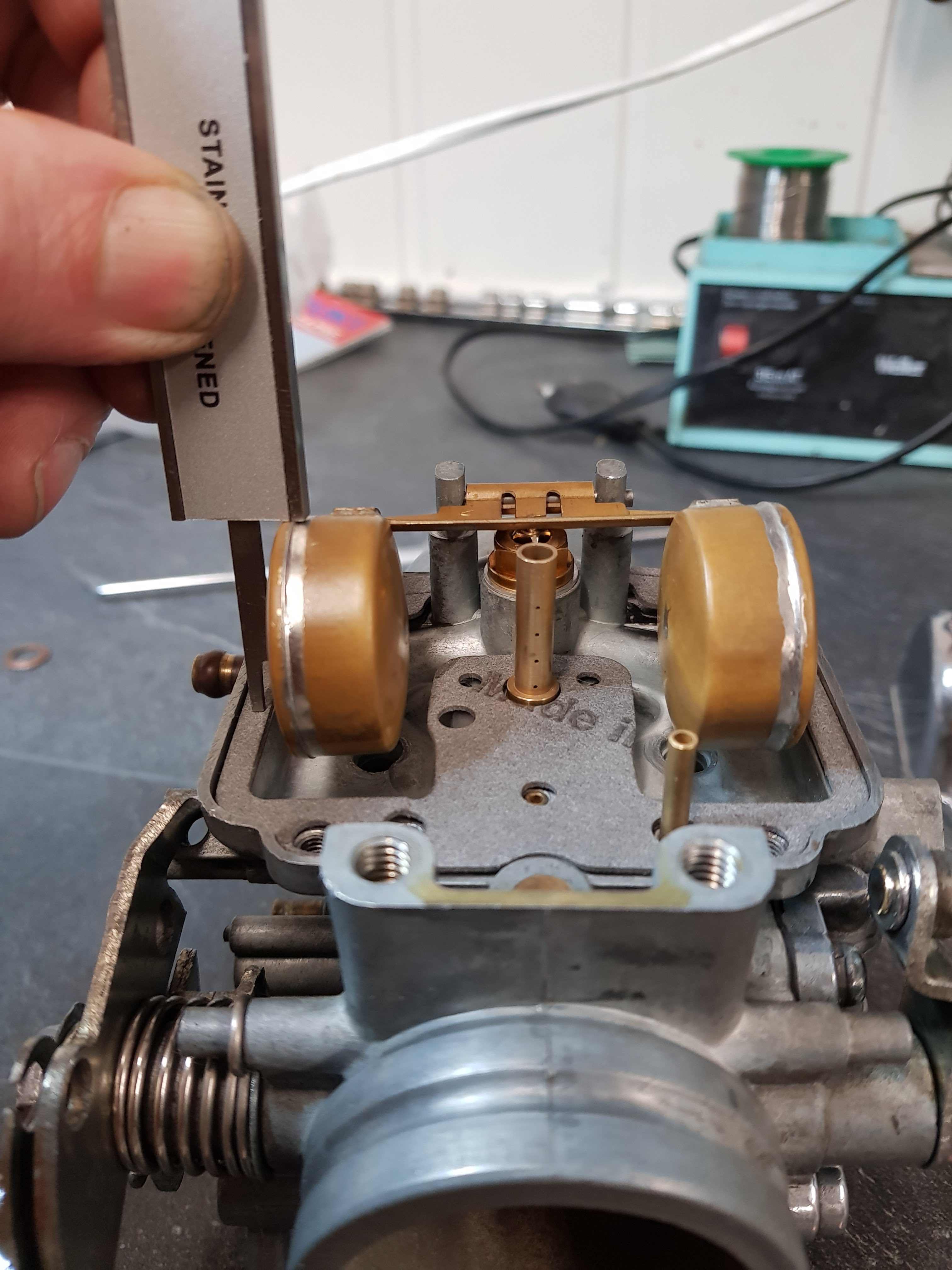
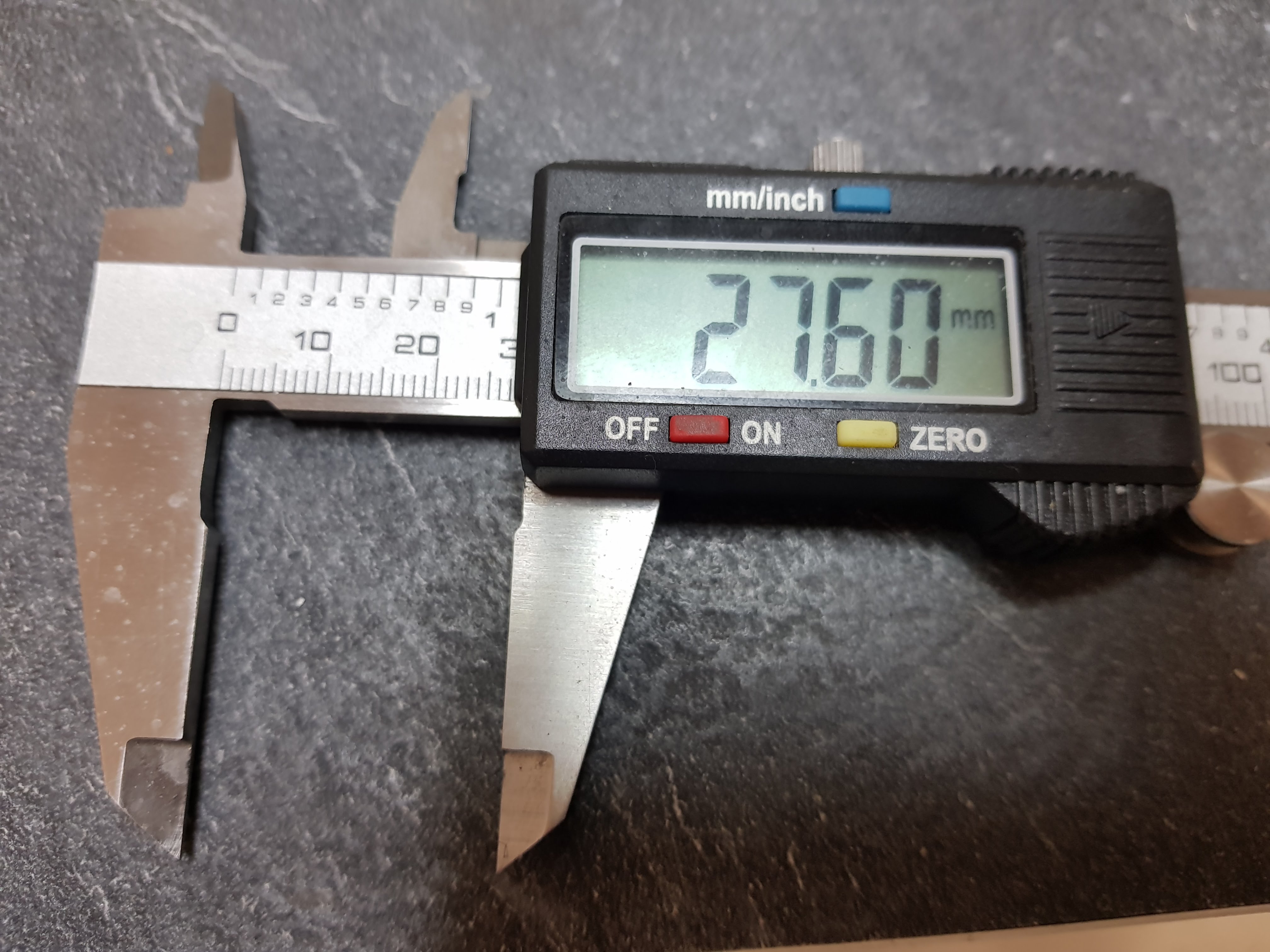
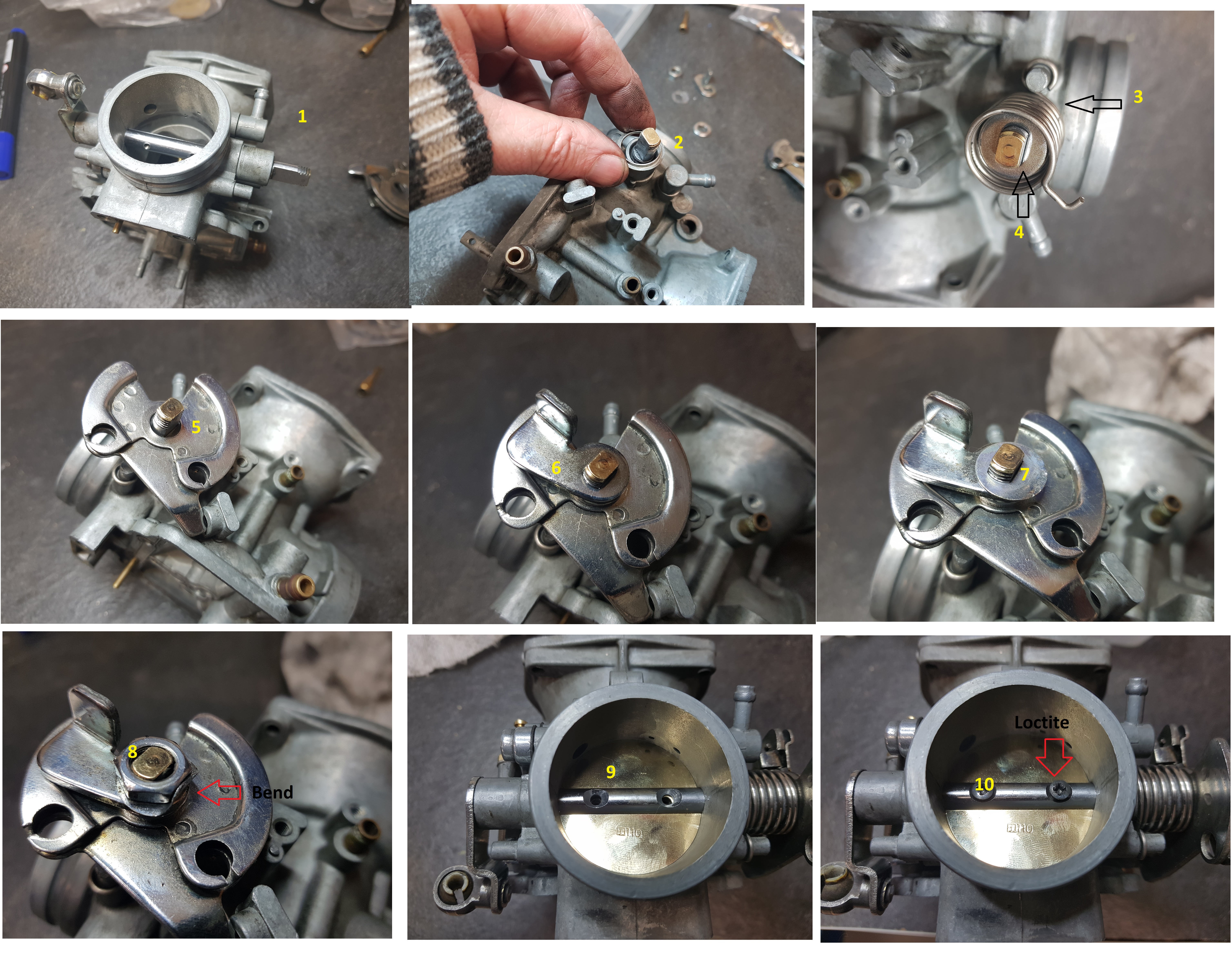
Adjust the height of the float by measuring from top of the float and down to the chamber attaching face. Not down to the gasket as it’s done on the photo. Open the Suzuki carburetors service manual for more information. Yes, you find it on my blog.


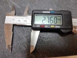
If the original needle valve is used the height should be 27,6 mm .Some of the aftermarket needle valve should be adjustet to 26mm due to a bit different design. Do the adjustment by bending the tab touching the needle valve.

Tilt the carb about 15-20 degrees to avoid the gravity to influence on the float and the needle while you do the measurement.

Step 5

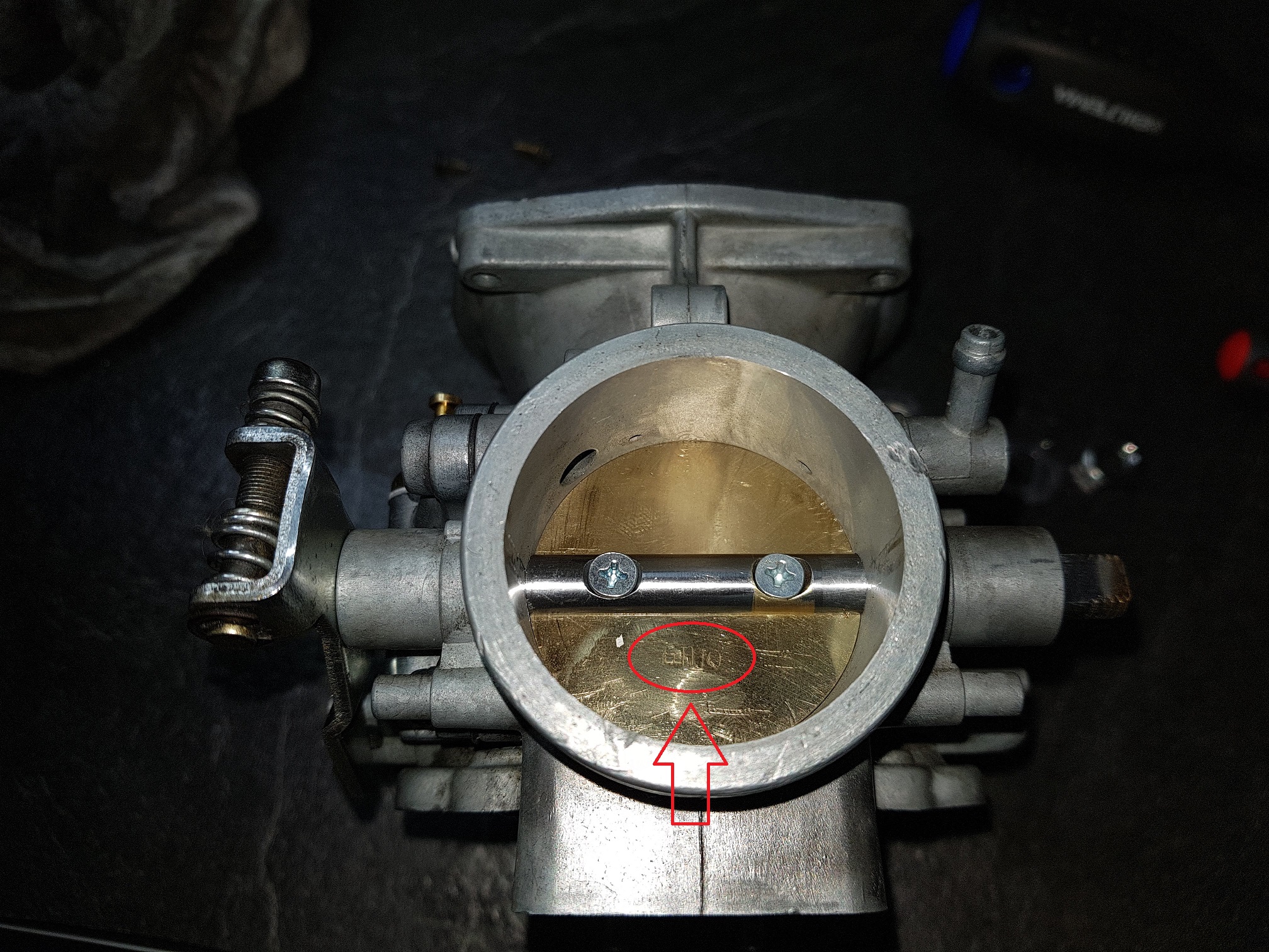
Installing the main jet.

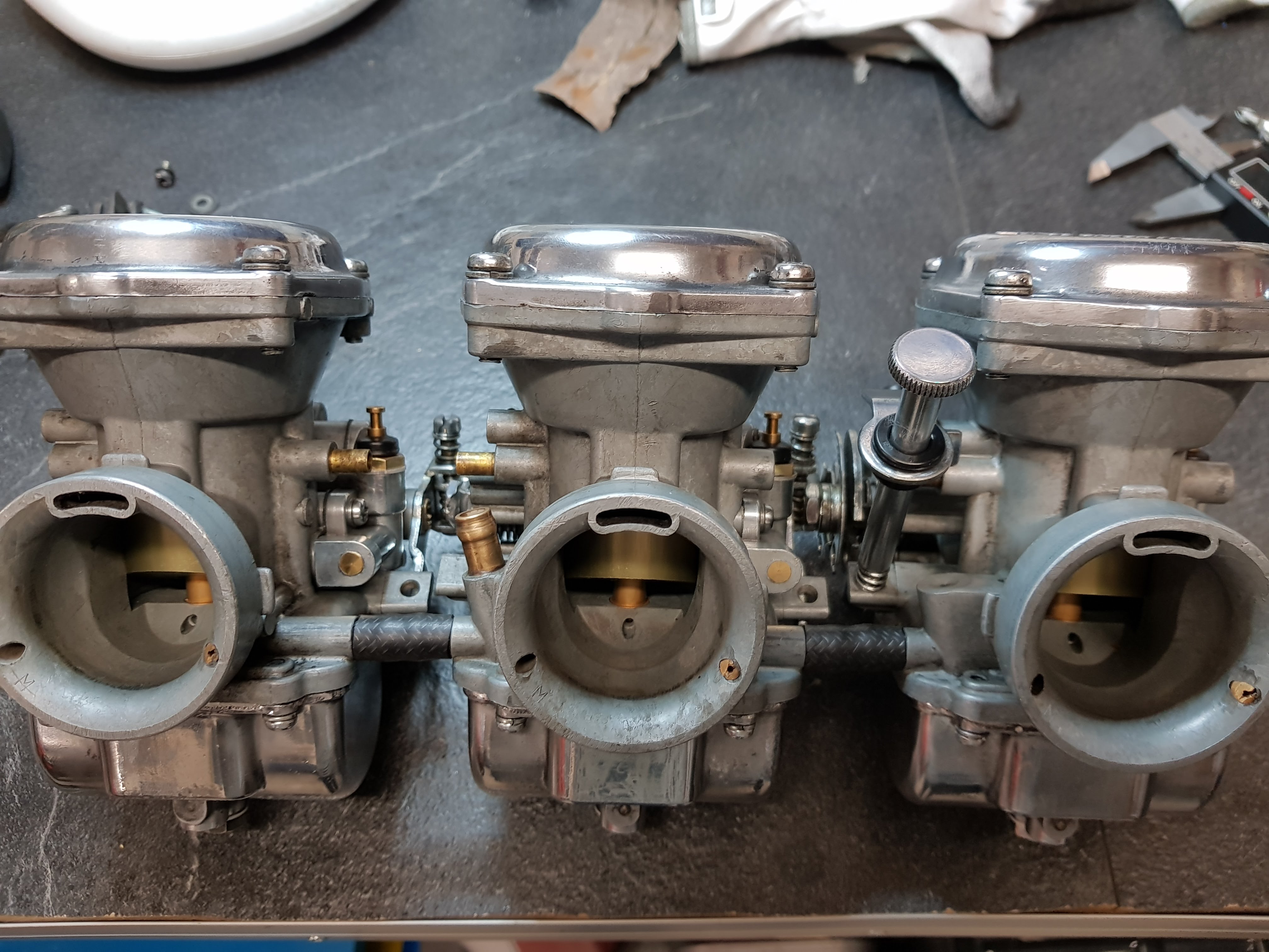
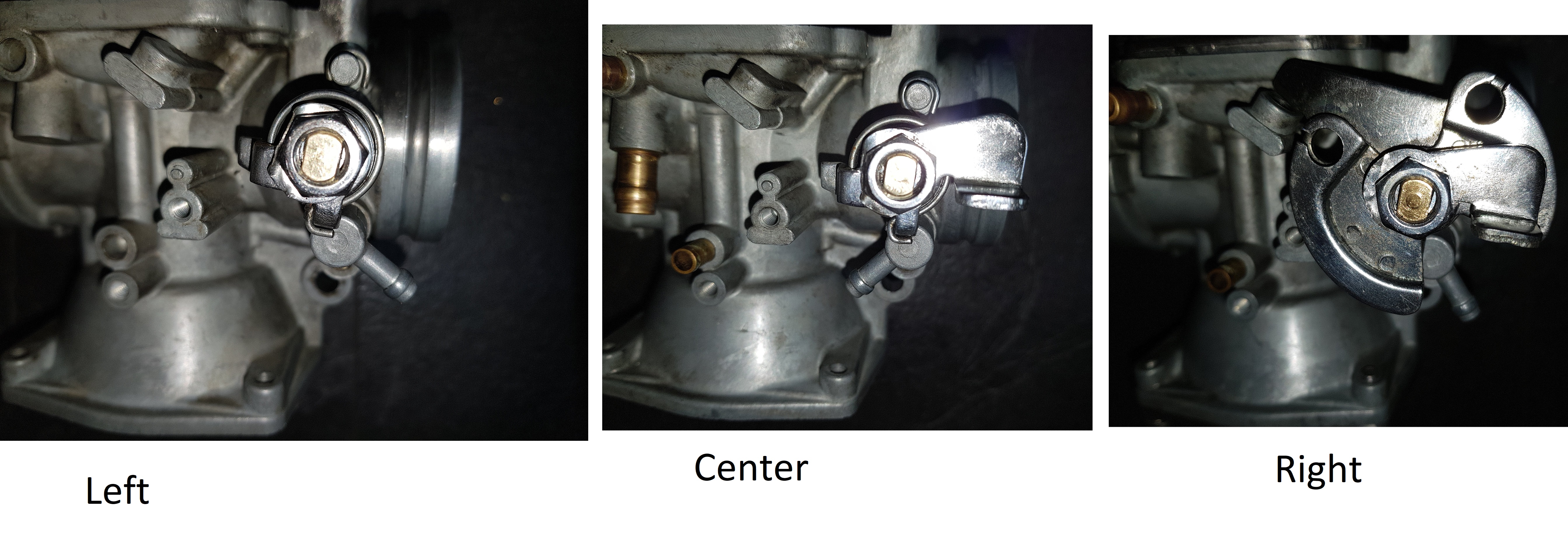
The correct size is 110 for the right and left carb. 107,5 for the center carb.


Step 6

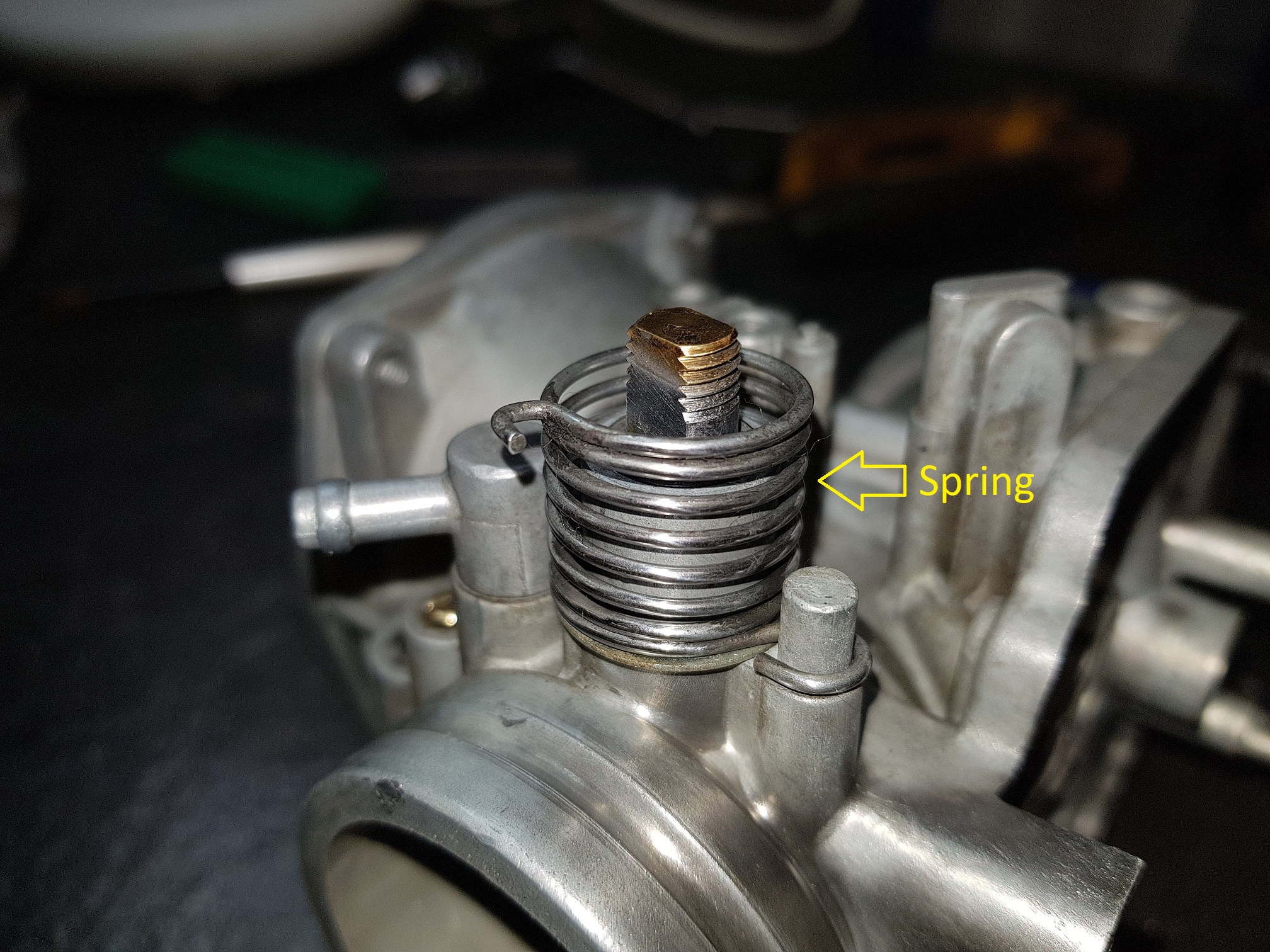
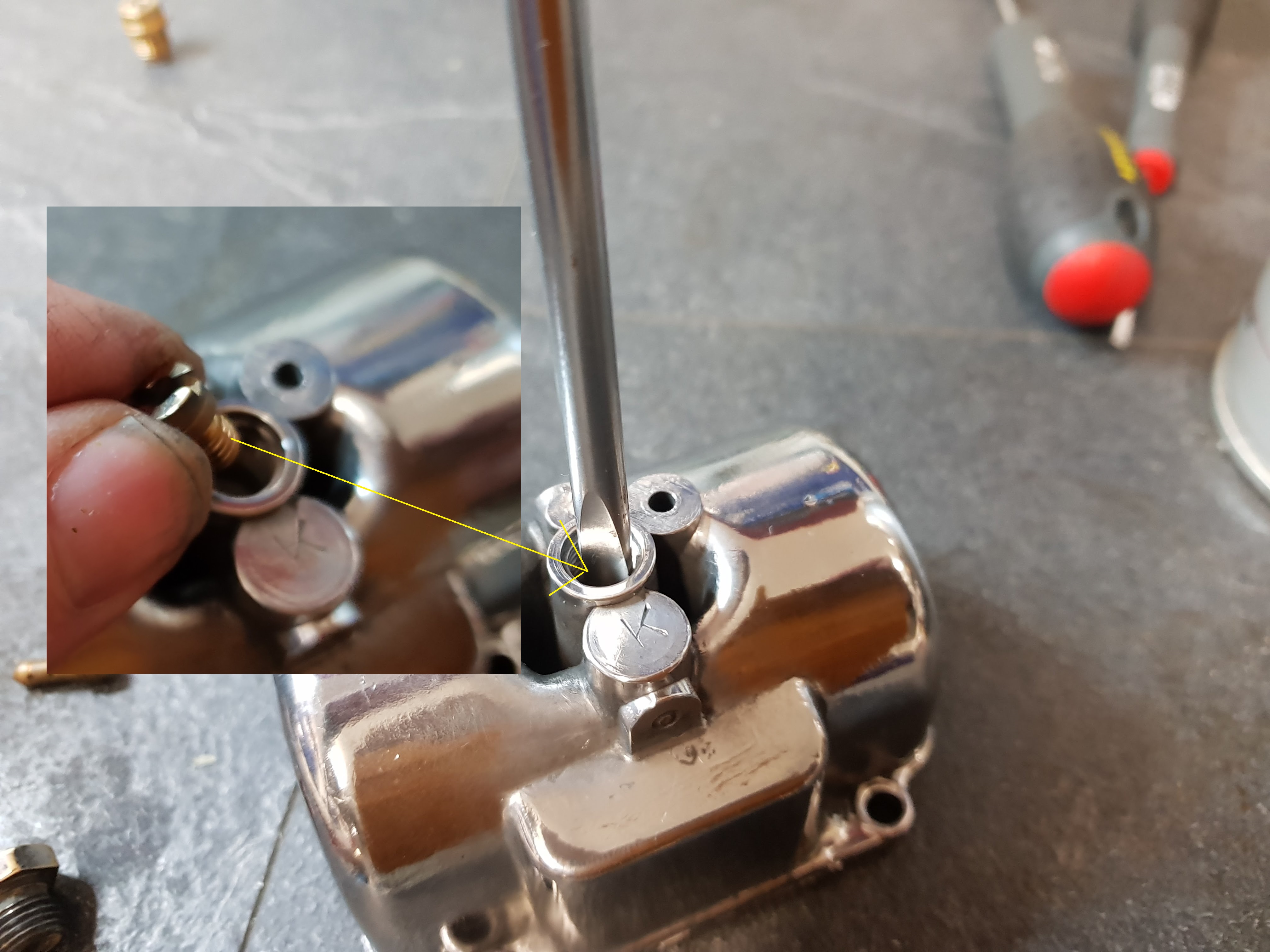
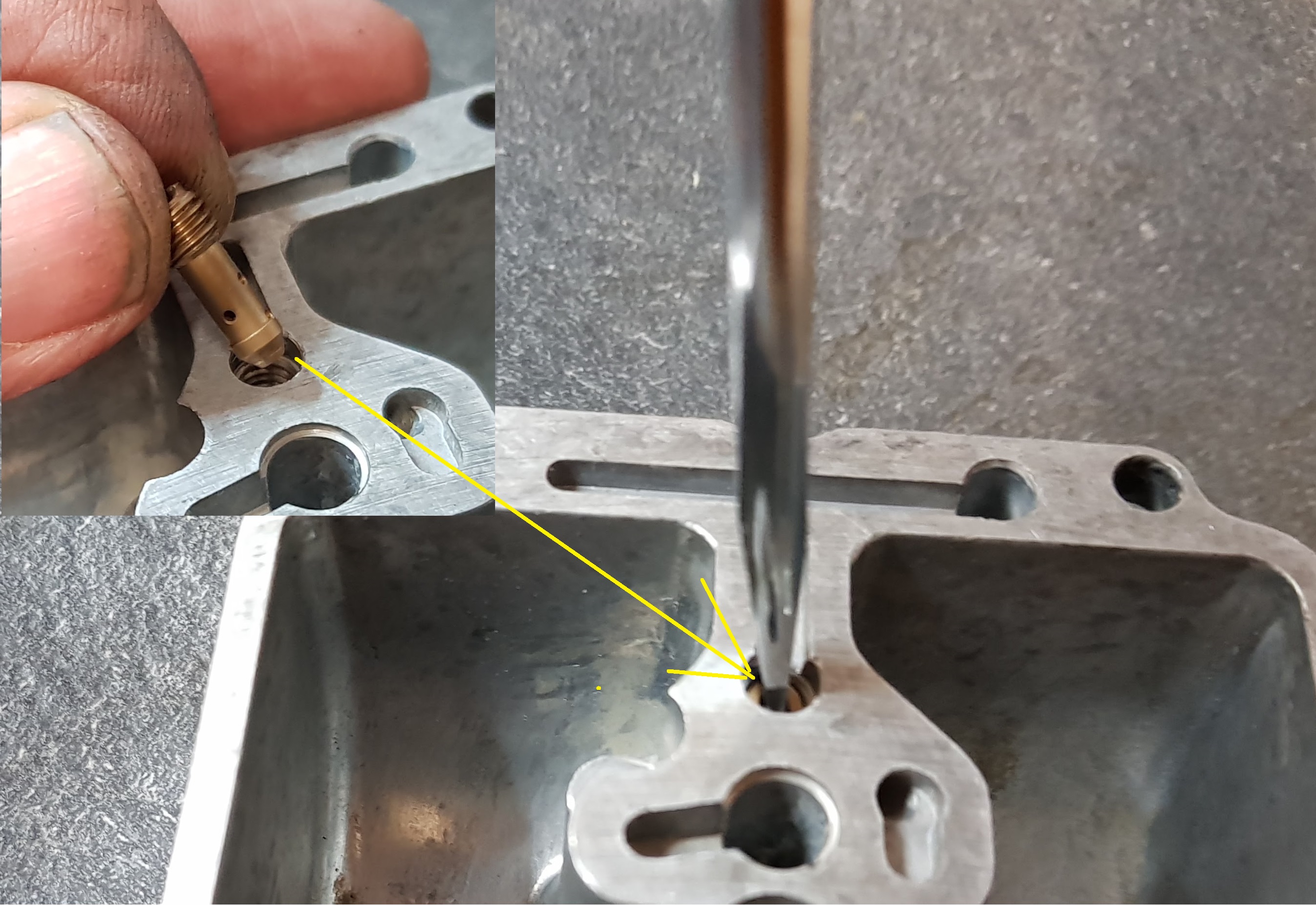
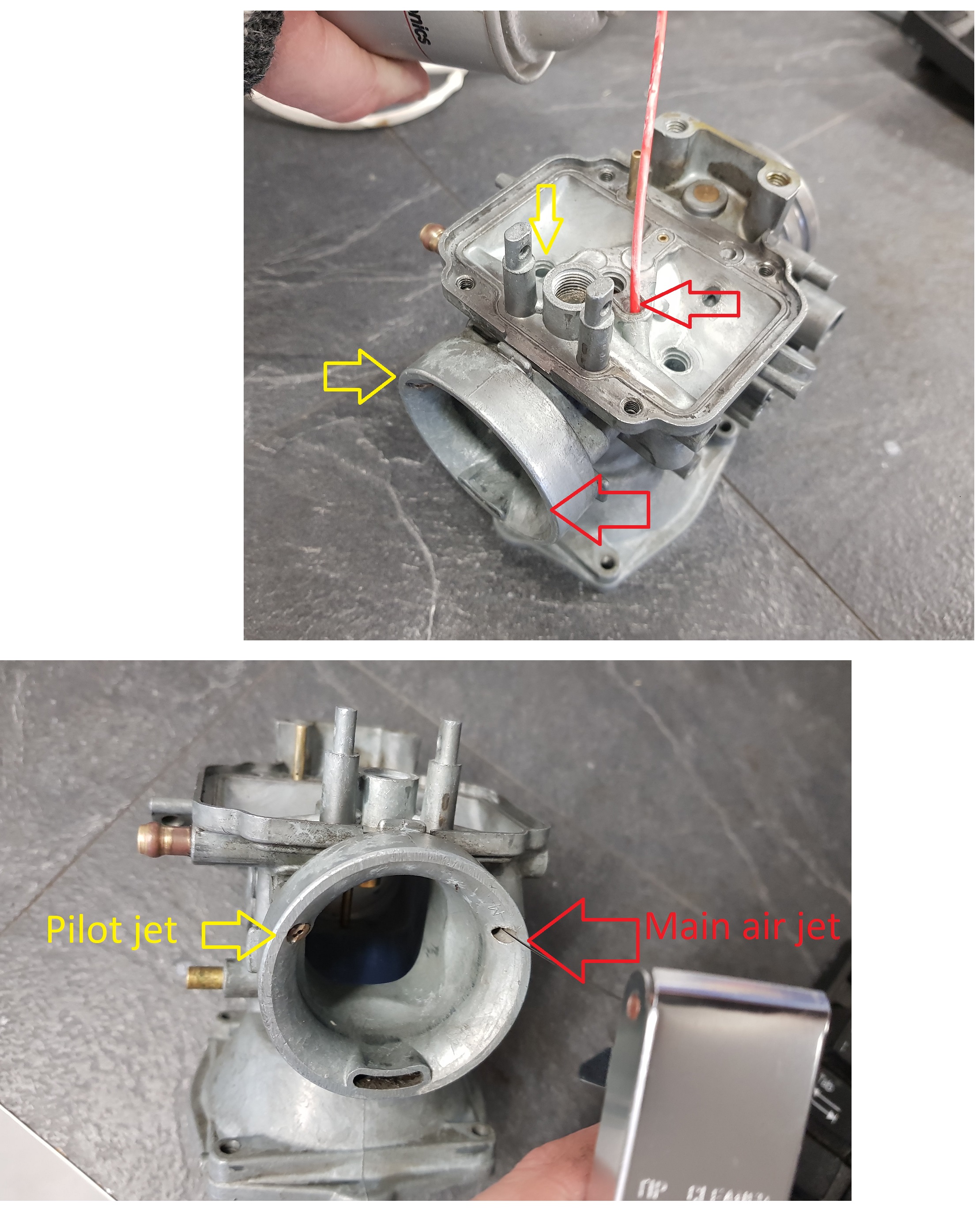
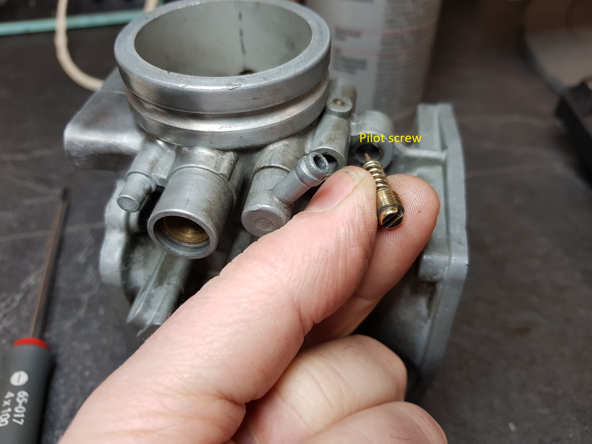
Installing the pilot jet

Screw in the pilot jet. Firm, but do not over tighten.

Standard jet size is 47,5. The jet in the picture above is 45 and is probably installed because the bike has been importet from US.  Emission laws in CA were more strict compared to Europe and they used diffrent jets. I fitted the one from the aftermarket kit with the correct 47,5 size

Step 7

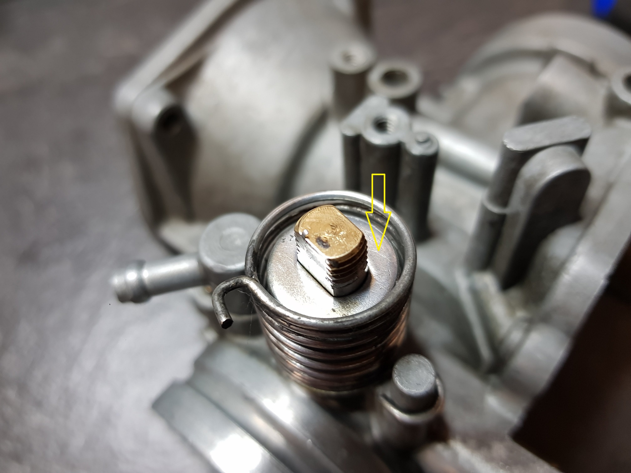
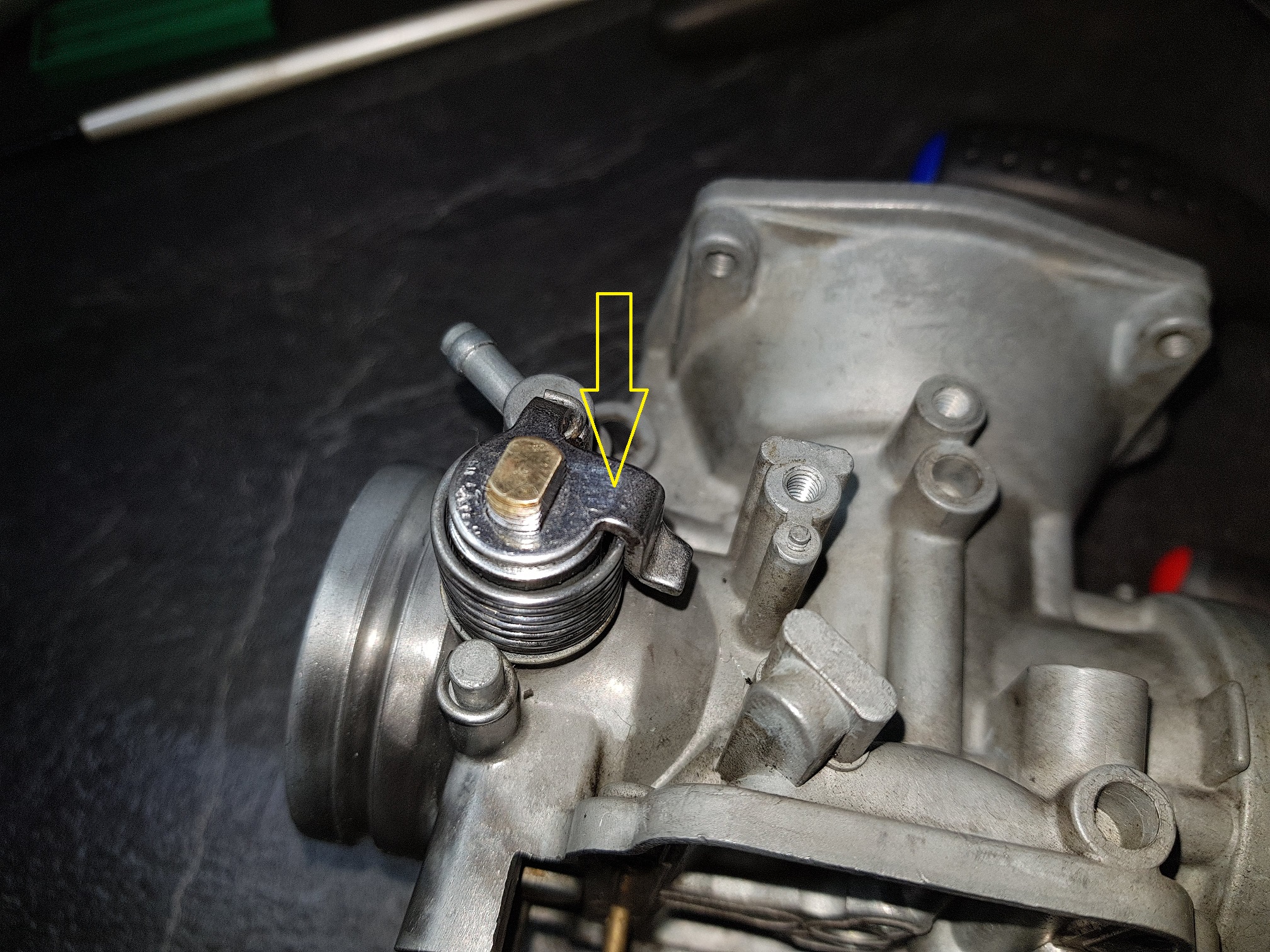
Install the drain plug ( and the washer )

Fit the float chamber with the four screws.


Jet cleaning

Before using carb cleaner and compressed air wash the carburetor using brushes and if possible, use ultrasonic cleaner as well.

Main jet and Pilot jet

Spray carb cleaner or other type of solvent through the main jet and pilot jet. The main jet is 0,5mm and the pilot jet is 1mm. If anti surging jet is mounted  (as on the picture) the pilot jet is reduced to 0,8mm

Clean well using solvent+compressed air and use a string at proper diameter for cleaning.


Pilot pipe cleaning

Mount the pilot screw before proceeding

Mount the pilot screw. Fully in, then 2/4 of a turn out again.


Cleaning

Spray carb cleaner into the pilot inlet. Make sure it’s a good flow throgh the output.


Fuel inlet

Clean the fuel inlet using a brush and carb cleaner. Use compressed air to clear.


Starter jet

Clean the starter jet as well. Hold your finger at the top and flush the jet. This can be quite often blocked.


Pressed in starter jet

Check to see you have a good flow through the pressed in starter jet.

  • 1
  • 2