Browse Category: Suzuki GT750 Engine overhaul

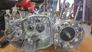
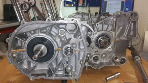
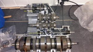
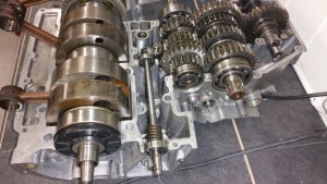
When I did the first restaurtion of the bike the engine was not opened. It was running fine exept from some loss in power from time to time. I thought it was an issue with the carburetors / fuel system. Later on I understood it was related to the sealings in the crankshaft. Had to start all over again, the engine out of the frame and get going with the overhaul of the engine.

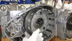
Assembling the clutch and the kick starter

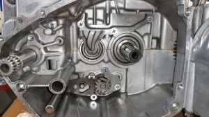
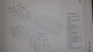
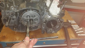
The photo below shows how I did the assembly of the clutch and the kick starter.


Step 1: Fit the oil guide plate. Drive all three screws well home. If you are to use thread locker or not depends on your religion. Do you believe in it or not. Someone says ” don’t use it, you will never get them loose”. Others say….And I’m not gonna tell you what I did .

20160401_152316


20160401_213525


Step 2:

20160401_175959

Mount the shim ( no.16)


Step 3:

20160401_180437

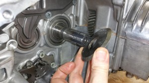
Mount the spacer, chamfer side goes in back.


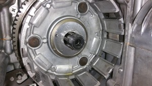
Step 4:

20160401_181224

Mount the clutch


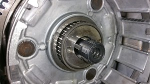
Step 5: 

20160401_181938

Mount the bearing assembly

20160401_181955


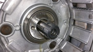
Step 6:

20160401_182819

Mount the spacer, chamfer side at the front.


Step 7:

20160401_183235

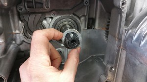
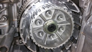
Mount the clutch sleeve hub (5),  locking washer (7) and center nut (6)

Always use a new locking washer, not the old one like I did on the photo.Why did I use the old one ? I didn’t know I had a new one until I had completed the assembly process. Can save the washer for the next time.


Step 8:

Torque setting for the center nut is about 50 Nm.

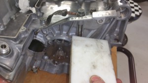
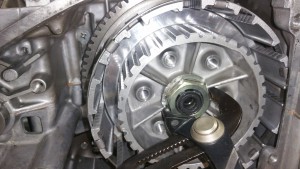
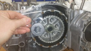
Before torquing up the center nut you need to some how lock the sleeve hub (5) Never use a screwdriver on the edges. You can make a special tool using old steel plates from a clutch. I had no such tool but did it in this way:

20160401_184551

Lock into one of the gears and do something clever to lock the front sprocket, like I did on the photo above.

20160401_191002

Don’t forget to bend the “new” lock washer. One of the edges is enough.


Step 9:

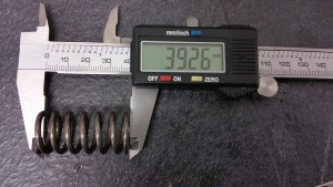
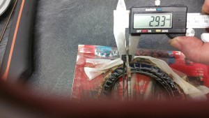
Before mounting the clutch check the specifications of the cork plates and the springs

20160401_173043

STD lenght: 40,4mm. Spring setting limit :1,4mm

    20160401_173409

STD thickness: 2,9-3,1mm. Wear limit: 0,2mm


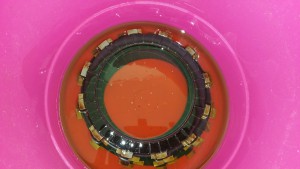
20160401_152337

Let the cork plates be quite oily before you mount them


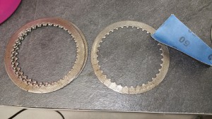
20160401_153522

Grind off any layers from the steel plates.


20160401_213012

Start with the cork plate, then the steel plate. The last plate should be a cork plate. The steel plate has a little radius on one side and a flat side on the other side. The flat side at the bottom and the radius facing  against the front.

8 cork plates and 7 steel plates.

And as you can see, I found the new lock washer after I had completed the assembly.


Step 10:

Mounting the clutch pressure disk.

20160401_213741

20160401_214348

Remeber the mount the clutch release shaft (17)

Mount the bolts in a pattern for an even distribution of the force. When all bolts are driven home you just give it a tap . No torque settings


Step 11

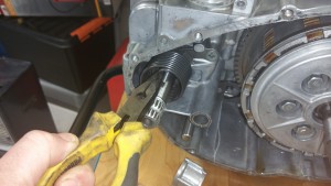
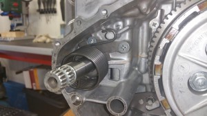
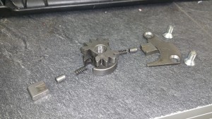
Kick starter

20160402_114322

Mount the spring holder (and the plate behind if not already mounted)


20160402_114717

Mount the spring

20160402_114537

Competed !


Step 12

Mounting oil seals, gasket and side cover

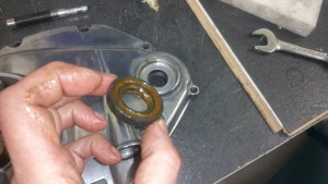
20160402_181930

There are two oil seals in the cover, both should / can ( depends on age) be replaced. Add grease on the seal side.


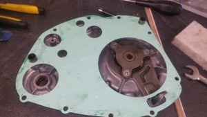
20160402_182823

I found both mounting studs quite stuck in the cover, not at the case side. Therefore I put the gasket at the cover side.


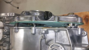
20160402_182953

20160402_183139

Done !
 

Case closed

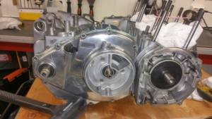
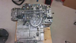
Phuu, the crankcase is finally sealed and closed.

Please see the summary of how I did it: ( And this is not the time to say I did it wrong, not in a mood to undo, please let me stay happy )

Step1:

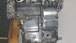
Cleaning the surface and do a test assembly to verify it’s all good.

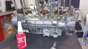
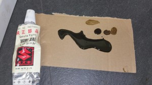
I had a tube of the genuine Suzuki seal but I was afraid to use it. The first impression was a thin soup, looking more like an old oil leakage from 1976 🙂 Therefore I bought something more modern from Loctite.

Loctite 574Suzuki seal

After some evaluation and testing of the Suzuki seal I think it’s might be good after all. After few minutes in air it changes to a more sticky paste. Totally different from the Loctite 574. The Loctite is curing after it is pressed against the alu surfaces, not in air. Then, what to use ? Since I had bought the modern stuff from Loctite and it’s made for this purpose I took the Loctite and applied the glue according to the instructions in the data sheet. It’s recommended to apply in one string and on only one surface. On the bottom case I only took some glue around the o-ring connecting the water pump. Remember to add  some silicone seal around the black plastic cover at the end of the gear shaft.

20160325_102315


Step 2

Mount the top case and install all the bolts on the top side. Secure the bolts but don’t use the maximum torque at this stage.  Check to see the crankshaft is still movable.

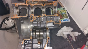
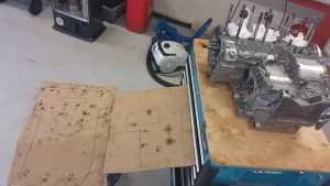
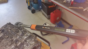
Turn around the engine to the bottom side and mount all the bolts according to the correct torque settings. And now is the pay off time for using a carton to keep track of the placements.

20160325_114438

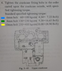
Please see the placement order and torque settings below. I have labeled 6mm bolts blue, 8mm green and 10mm yellow.

Click on the images for detailed information

Since I live in Norway I use Nm as tourque settings.
10mm bolts 32Nm
8mm bolts 15 Nm
6mm bolts 8 Nm

Torque20160319_135520

20160325_105436

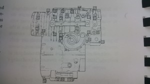
Bottom torque sequence

20160325_104630

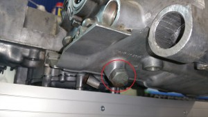
Bolt no 13 need a copper or alu washer + some extra silicone sealing


Top torque sequence


Step 3

Installing the tachometer drive.

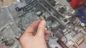
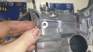
Mount a 6mm screw at the top to secure the inner part.

20160325_111757


20160325_112203

Tap the drive down to the position where you can see the mounting hole for the screw.

Step 4

Enjoy the work, dry off remains from the seal and do something clever to avoid parts falling into the engine.

20160325_112720

20160325_111033 20160325_111017


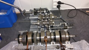
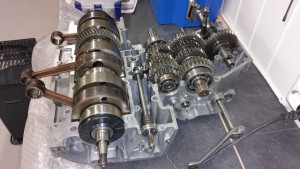
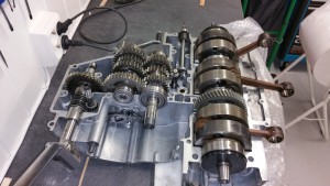
Am I ready ?

Hmm, what is missing before I glue and mount on the upper part of the crankcase…. Am I good to go ? I will double check up against instructions on the DVD. If anyone see something missing, PLEASE let me know.

20160308_214254

20160308_214322

20160308_214335

20160308_214301

Upper part of the crankcase

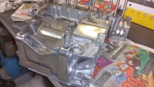
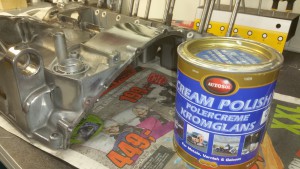
Started the day planning how to mask and paint the upper part of the crankcase. The lower part is left as naked raw aluminium as it came from the factory in 1976. I know it’s common to paint both parts as it will look better, at least in the beginning before the lower part of the crankcase is getting worn after some time on the road. Then I got a second thought, why not polish the parts. All side covers will be polished and if I polish the visible parts of the crankcase it might look good. And I don’t have to worry about any damage on the paint during the assembly process.

Here is the result:

20160306_185911

20160306_185940

I think the result came out quite okay using AutoSol.

20160306_190038

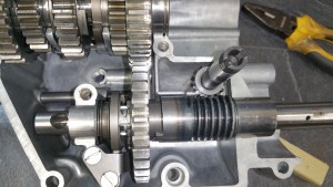
Kick Starter Sequence

Here is the sequence of the kickstarter. I had to assemble without paying attention to the alignment marks, because one of them is not present. ( look at my privious post )

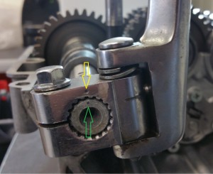
Both punch marks at the end of the axle and the kick starter are present and aligned.

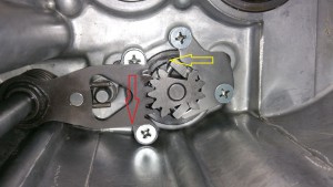
Sequence 1B

See the punch marks at the yellow and green arrows.


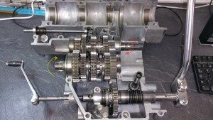
Sequence 1                       Klick on the images for details

Sequence 1

The front shaft is connected to the clutch and will rotate like the red arrow shows.

The rear shaft is connected to the front sprocket and will rotate like the yellow arrow shows.

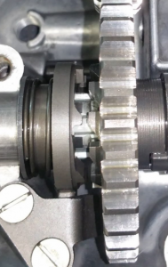
The little clutch on the kick starter shaft is in released position and is not in contact with the rotating gears.

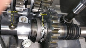
Sequence 1A

The oil guide hole is also facing upwards. Everything should be okay.


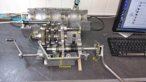
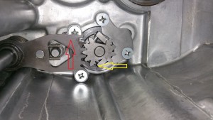
Sequence 2

Sequence 2

The engine is stopped and we try to restart the engine by kicking down.

The little clutch will connect and the rotations on the shafts will be according to the yellow arrows. And of course, in the same direction as while the engine is running.

When the kick starter is released it all goes back to sequence 1

Kick Starter

This was a bit tricky, I need some FB help to verify my assumptions.

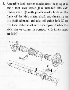
As far as I understand this is the correct assembly of the kick starter.

20160225_200352

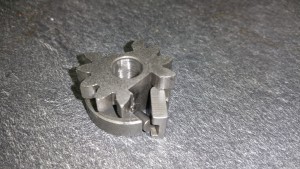
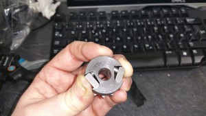
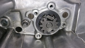
The oil guide hole (3 in the drawing below) is facing upwards and the kick starter is in contact with the kick starter quide 4.

In this position the motor can run and the kick starter is in released position, free from any contackt with the gears. See the next picture.


released

No contact with the gears.

So far so good, but now it all fells apart ? Map and terrain does not fit anymore.

Punch mark

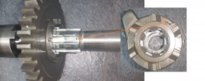
In all manuals and also on the DVD from the Kettle clinic it shows a punch mark on the starter shaft and the spline on the shaft. They have to be aligned. If I do so it all comes out wrong and the oil guide is not longer facing upward when the kick starter is in contackt with the kick starter guide.

It looks like it’s only a punch mark on the kick starter shaft on my bike. The second mark is difficult to find. There are som scratches and a groove but nothing like a punch mark. See the next picuture. (click on the image for details)

20160225_193855

If I align according to the orange arrow the facing of the oil guide hole comes out wrong.


Compare the assembly against the instructions at the DVD.

20160225_201241


If I don’t care about the punch mark and try to mount according to the DVD from the Kettle Clinic it looks alright. The oil guide will face upwards as it should when the kick starter is in released position ( disconnected from the gears )

Please give me some feedback about this issue.  When I’m 100% sure it’s all correct I might post a video showing the entire sequence of the kick starter in action.


Gear shifting

The fun part of the engine overhaul: Playing with the gear shifting

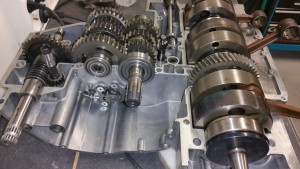
20160221_125220

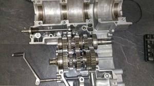
This weekend I have mounted the gear assembly. First I study the drawing in the service manual, spare parts manual, Haynes and Clymer workshop manuals, looked all over again.. ??? Perhaps I’m stupid or something, but I don’t get it. After the mounting process and playing with the gear shifting I think I have some answers.

Let’s go back and take one step at a time:

Step 1: 

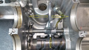
Look at the picture below. While shifting gear the CAM will rotate, and as you can see, the shifting FORK is fixed in the groove and will be moved to left or right depending of the track pattern in the shifting CAM

The gears are mounted on top of the forks and will therefore be moved according to the tracks in the CAM.

drum and fork

For detailed information about mountig the CAM and FORK, please look at my privious post ” Mounting the cam for the gear shifting”

Step 2:

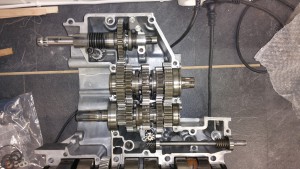
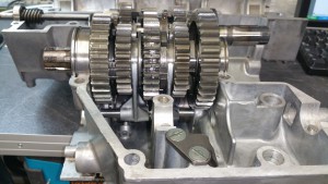
Mount the gear assembly according the the first picture on this post. Remember to mount the all C-rings for locking the gear shaft. Slide the front and rear gear assembly down into the forks.

20160220_164425

Rear assembly, notice the position of the forks. Rotaton of the CAM will slide the gears to left or right.


Step 3:

Mount the CAM stopper:

CAM stopper20160220_164453

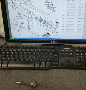
The spring loaded CAM stopper (items 17-20 on the drawing)  will prevent the cam to rotate out of its correct position.


Step 4:

How do we rotate the CAM ? We all know we are kicking the gear shifter down into the lowest 1-gear and upwards for the higher 2-5 gears. But how does the CAM rotate all the way ?

Shifting down:


shift down

Shifting down, the movement follow the red arrow og the rotation of the cam the yellow arrow. The upper little metal part is spring loaded and will be pushed by a tiny little piston into a cut out in the CAM. In this position it’s locked and will move the entire CAM to a left side rotation in the picture.
When you release the pressure from the gear shifter the spring loaded mechanism will return to right and grab into a new cut out, ready for a new rotation.


Shifting up:

shift up

Same explanation as above but opposite direction.


The  spring loaded mechanism in details:

20160220_160438 20160220_160659 20160220_161320

A bit tricky to keep all parts in position before mounting.


20160220_16150420160220_162057

Mount the brackets and use thread lock on the screws.


Step 5:

Check the gear shifting:

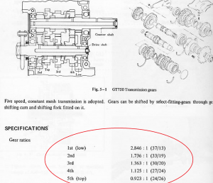
Gear ratio

The table above shows the gear ratio. I put a piece of tape on the outgoing axle aligned to the mark on the incoming axle from the clutch.

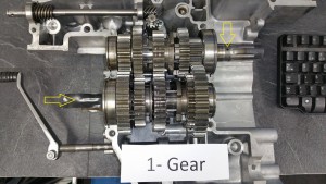
1-gear

20160221_125602

By counting the revolution on the incoming axle for one turn on the outgoing axle I got the same ratio as in the specifications. Almost three turns (2,8) in the 1-gear position for one revolution at the outgoing.


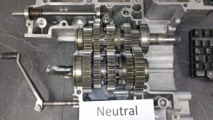
Neutral position:

20160221_125813


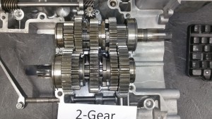
2- gear. Ratio of 1,7:

20160221_125954


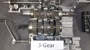
3-gear. Ratio of 1,3:

20160221_130209


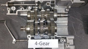
4-gear. Ratio of 1,1:

20160221_174109


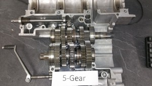
5-gear. Ratio of 0,9

20160221_174037

All gears are shifting according to the specifications. It would be stupid to proceed with the assembly without checking the gear shifting.

The gearbox is not without any worn parts. Based on the experience before dismounting it still shifts smooth and nice without any problems at all. I dont’ want to spend money and work on parts if it’s not needed.

I can sleep well tonight 🙂


Mounting the water pump

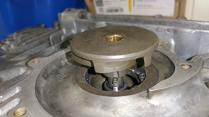
Finally, after a lot of discussion regarding the facing of an oil seal, it’s time to mount the water pump.

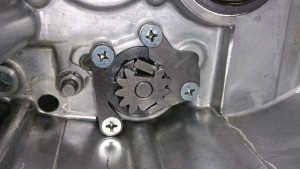
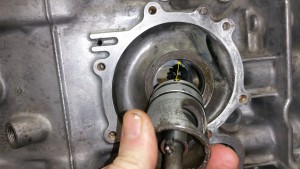
Align the pump:
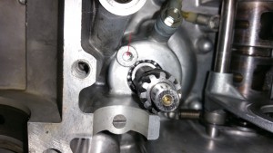
Use the mounting hole inside the case and turn the pump until it’s aligned to the groove in the pump, see the yellow arrow.

20160219_194932

Picture from the bottom side


Monteringshull

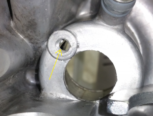
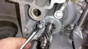
Align against the mounting hole for the screw


Monteringshull topp side

Mounting hole for the screw seen from the other side.


20160219_195248

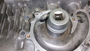
Use a socket for a more easy mounting. Push the pump all the way down.

When you see the groove for the big circlip you know it’s at the bottom.


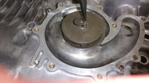
20160219_195455

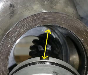
Check the alignment of the groove and the mounting hole, put a small screw driver into the hole and use it to turn the pump if it’s not in correct placement. Make sure the groove is underneath the hole. See the red arrow on the picture.


20160219_195736

Secure the pump using the correct screw. 6-10 Nm.


20160219_200251

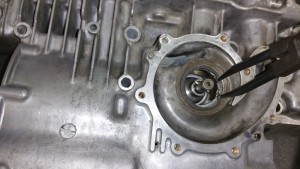
Mount the circlip

20160219_200338


20160219_200417

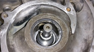
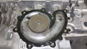
Mount the impeller


20160219_200510

Mount the circlip


20160219_203359

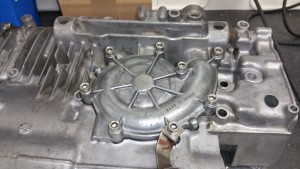
In addition to the new paper gasket you can add a thin layer of silicone gasket to secure the sealing


20160219_205418

Fasten the bolts, 6-10 Nm according to the service manual.

Powder blasting of the cylinder

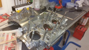
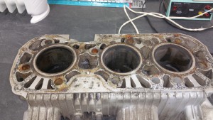
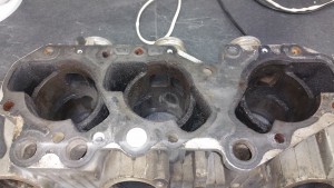
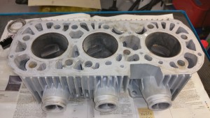
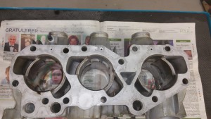
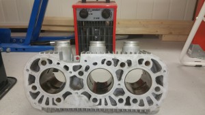
I got hold of a “new” cylinder for my bike. Seems to be in a good shape but is full of old burned oil. Not easy to clean. Can the powder blasting do the job ? Lets try ! The powder is ordinary baking soda and will not do any harm to the cylinder.
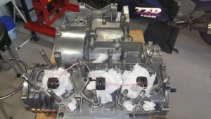
Click on the images for a close-up view.

Before the powder blasting:

20151210_190841 20151210_190937

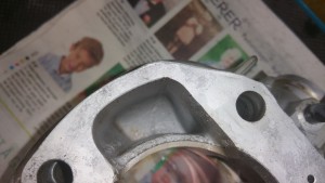
 After the blasting:

20160215_210614 20160215_212929 20160215_212921


Drying up after a wash with water and soap. A layer of WD40 inside the cylinders.

20160215_213551

I’m very pleased with the job. Nice and clean, like a new one from the factory.