Coils and capacitors
In this post I will try to give basic information about the electronics in the ignition system. The Suzuki service manual refer to two of the key components as Condenser and Coil. In fact , that’s a bit wrong. The condenser is a capasitor and the coil is a transformer made of two coils, one for the primary side and one for the secondary side.
Condenser / capacitor

Fig.1
The word condenser is common to use on components able to store or convert energi (ex:converting gas into liquid) but in electronics this device is more referred as a capacitor and I will use the word capacitor or CAP in the rest of my posts.
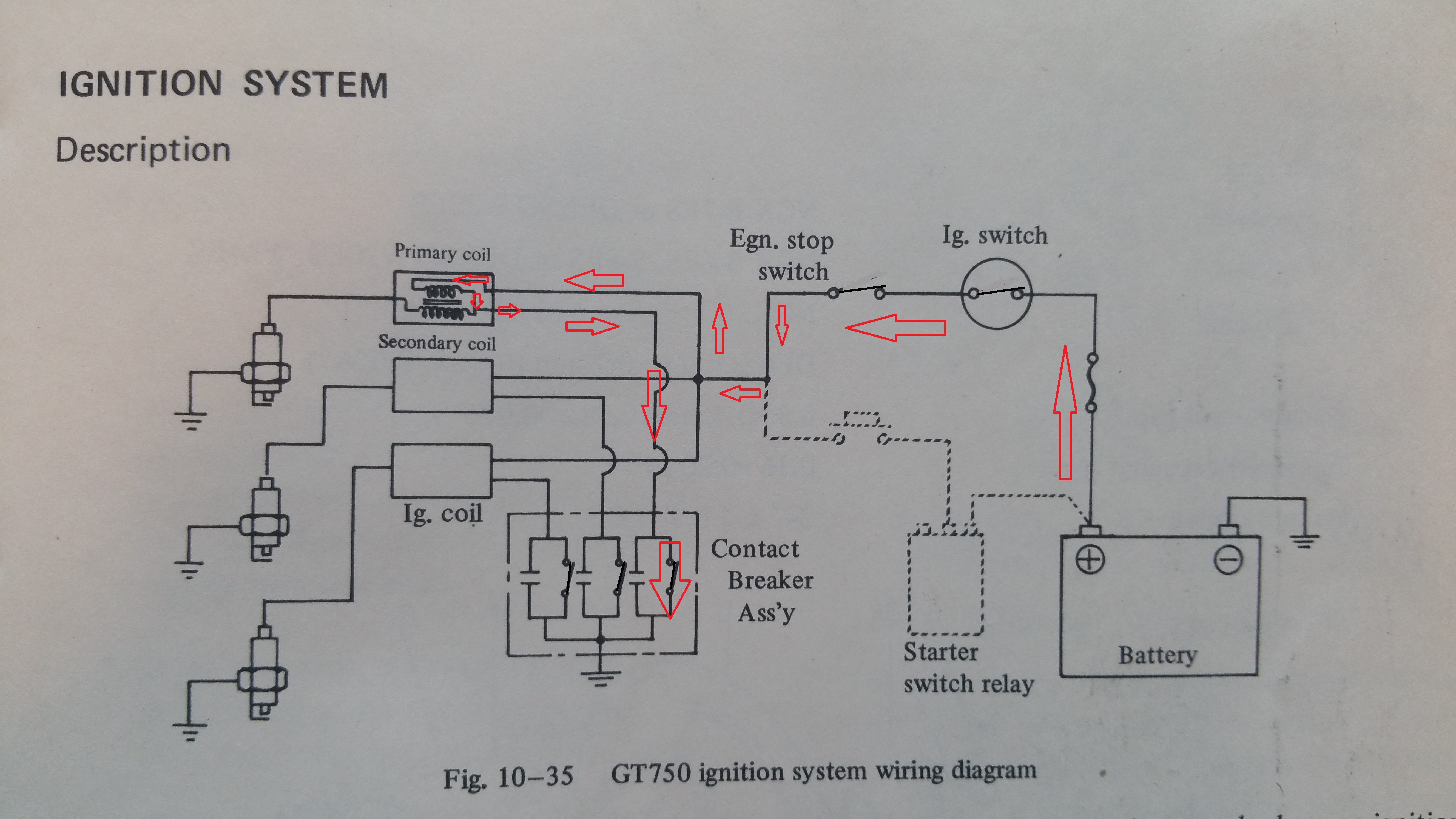
In fig 1 you can see three caps connected above each circuit breaker to protect the points in the breaker. One for each cylinder , Left, Centre and Right.

Fig.2,
In fig 2. you can see the electrical connections of the capacitor. There is only one wire connected, the yellow wire as shown in fig.1. Pin2 in the schematic symbol is internally connected to the body of the component and will therefore be grounded when mounted at the assembly plate. The schematics in fig.2 is only for one cyllinder. All together we have three coils, three circuit breakers and three capacitors, but one battery.
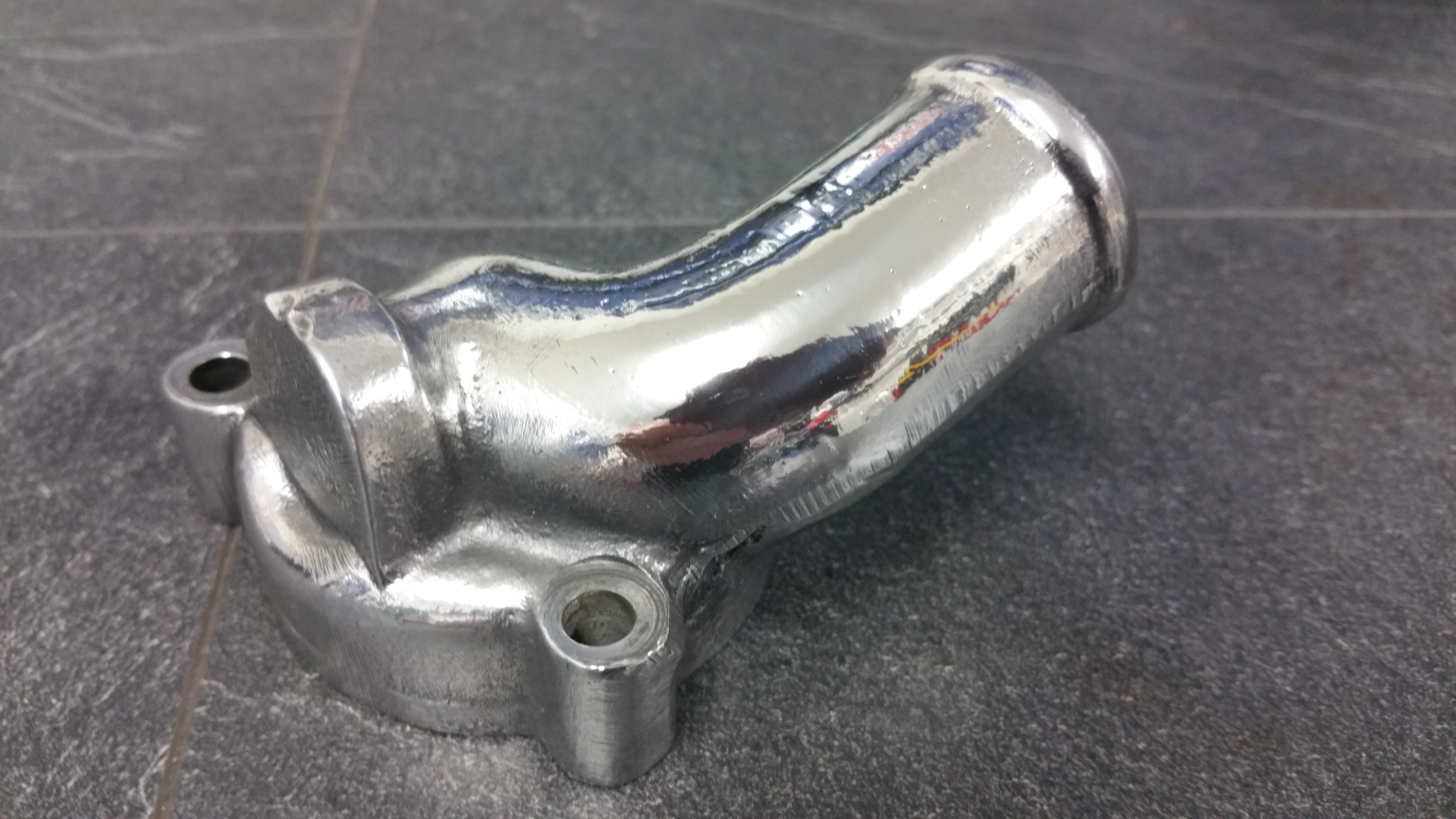
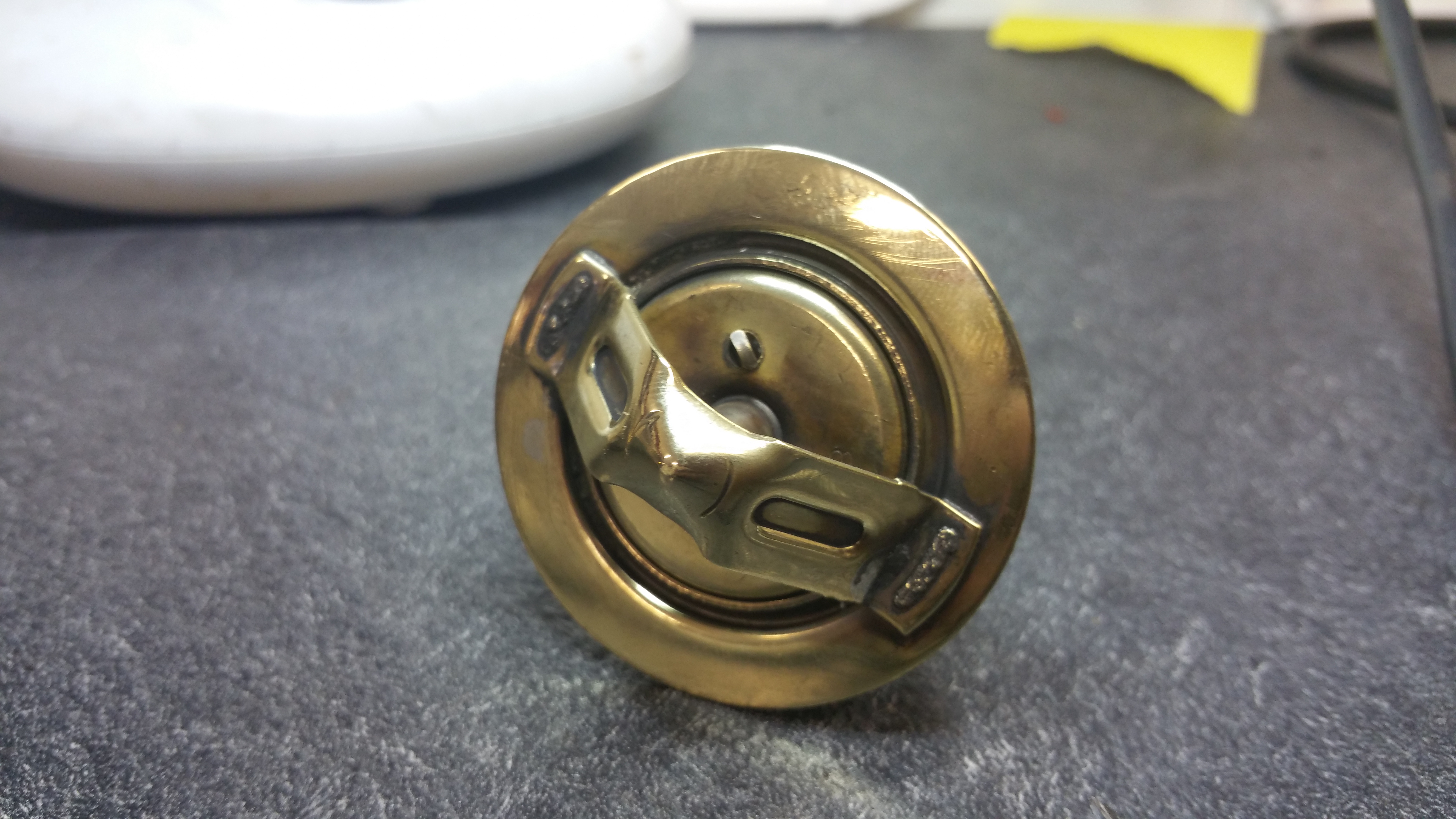
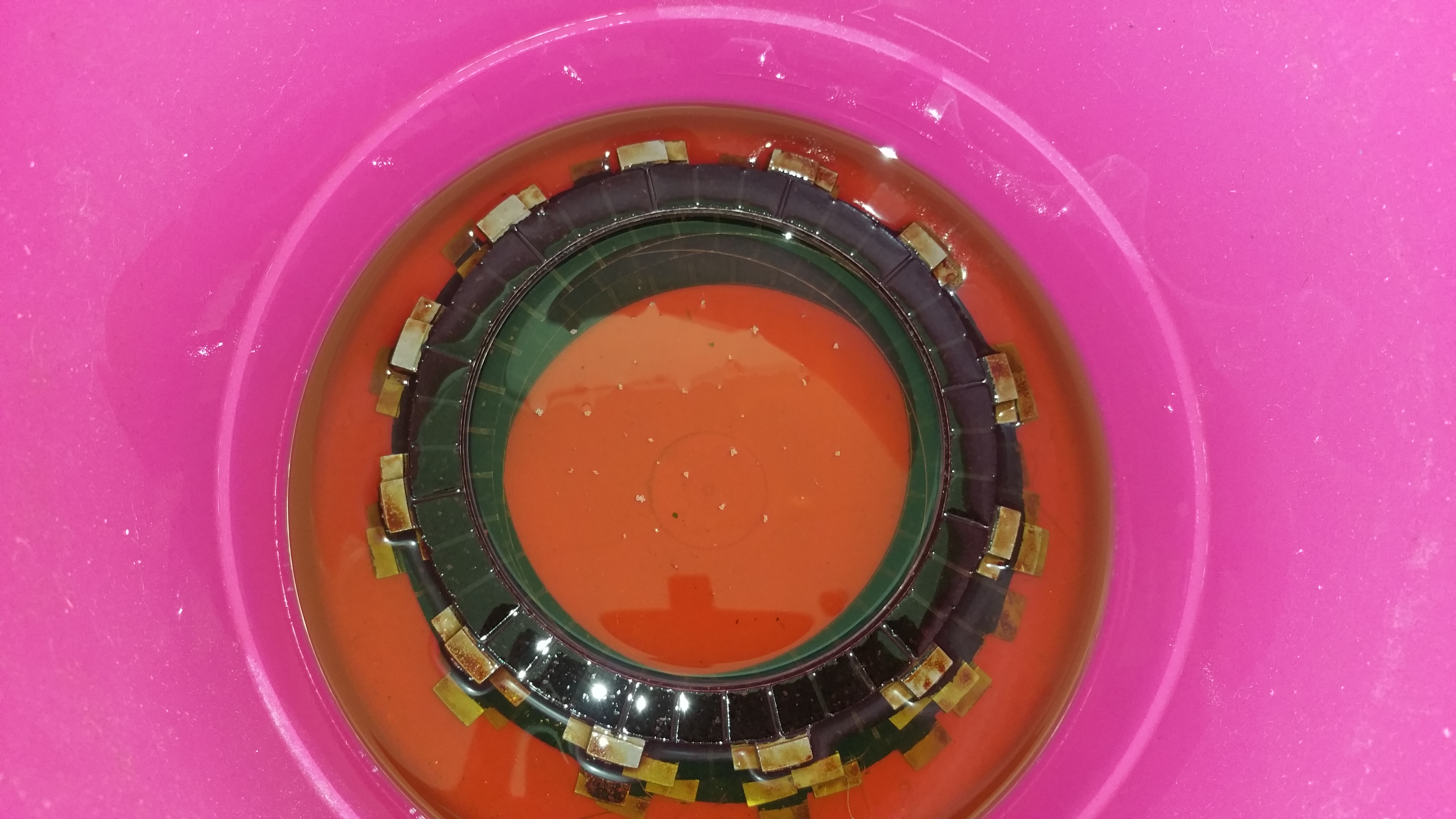
A capacitor consist of two metal plates (metal foil) with an electric insulated material in between. The Suzuki type is rolled and put in a can. That’s the reason for the shape of the cap.
If you apply voltage to a cap you will charge up the cap with current until it has the same voltage as you apply. Almost the same as a battery except from the speed. You can charge and discharge thousends of times within a second. The frequency can be many kHz. If we go above Mhz the performance will change and this type of cacitor will become a coil, but don’t worry, I will not discuss that now.
The units for measuring a cap is Farad. The value of the Suzuki cap should be in the range of 160-220 nF. That’s the same as 0,000000160-200 Farad.
How to measure the value :
If the capacitors are mounted and installed at the bike do the following:
Disconnect the wiring harness of the points from the connector, see fig.3
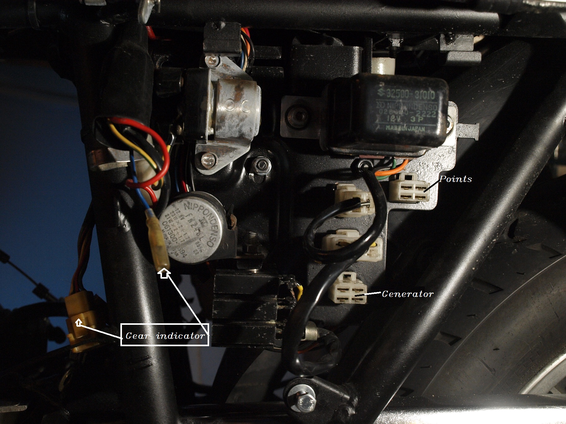
Fig.3
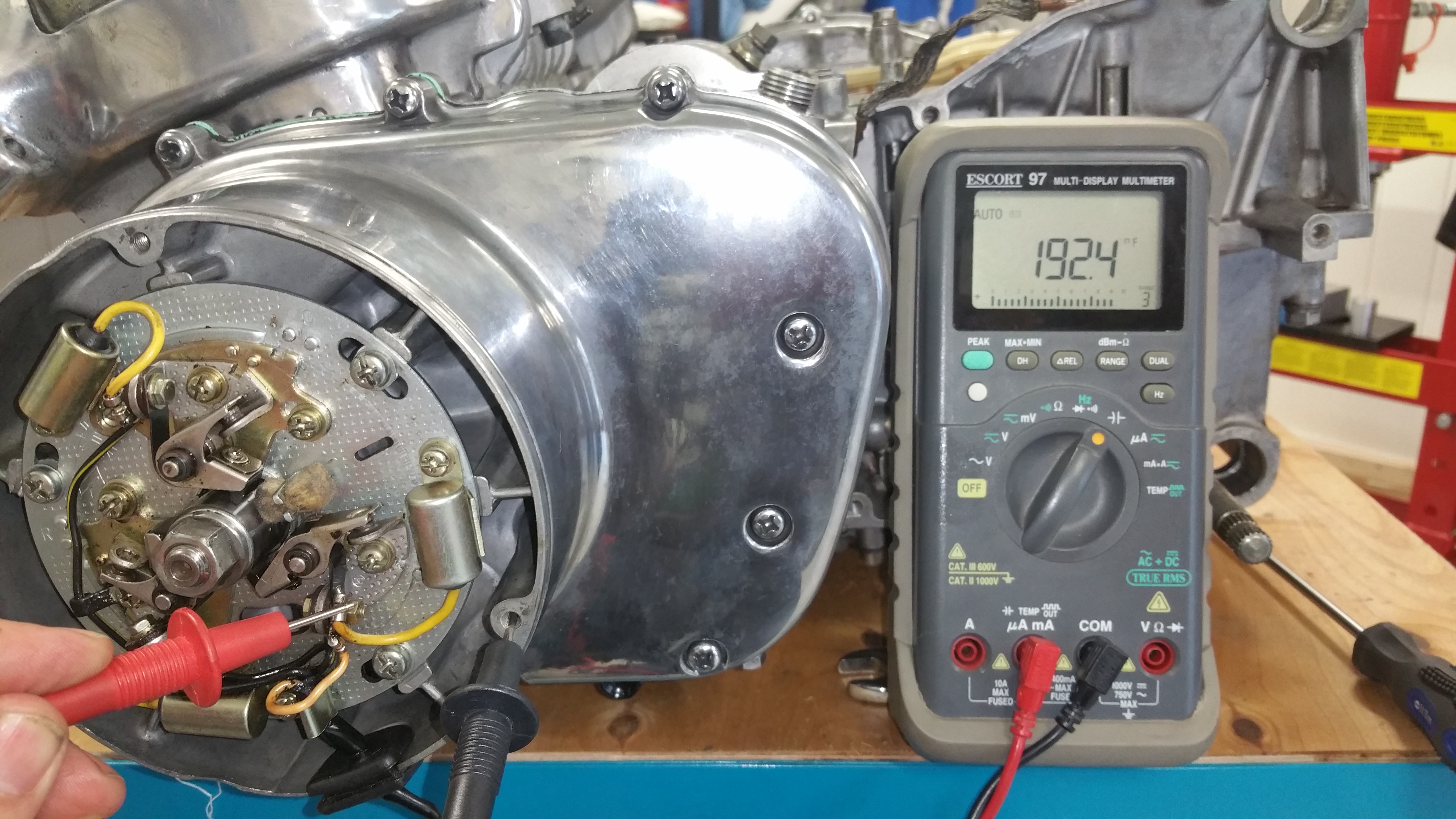
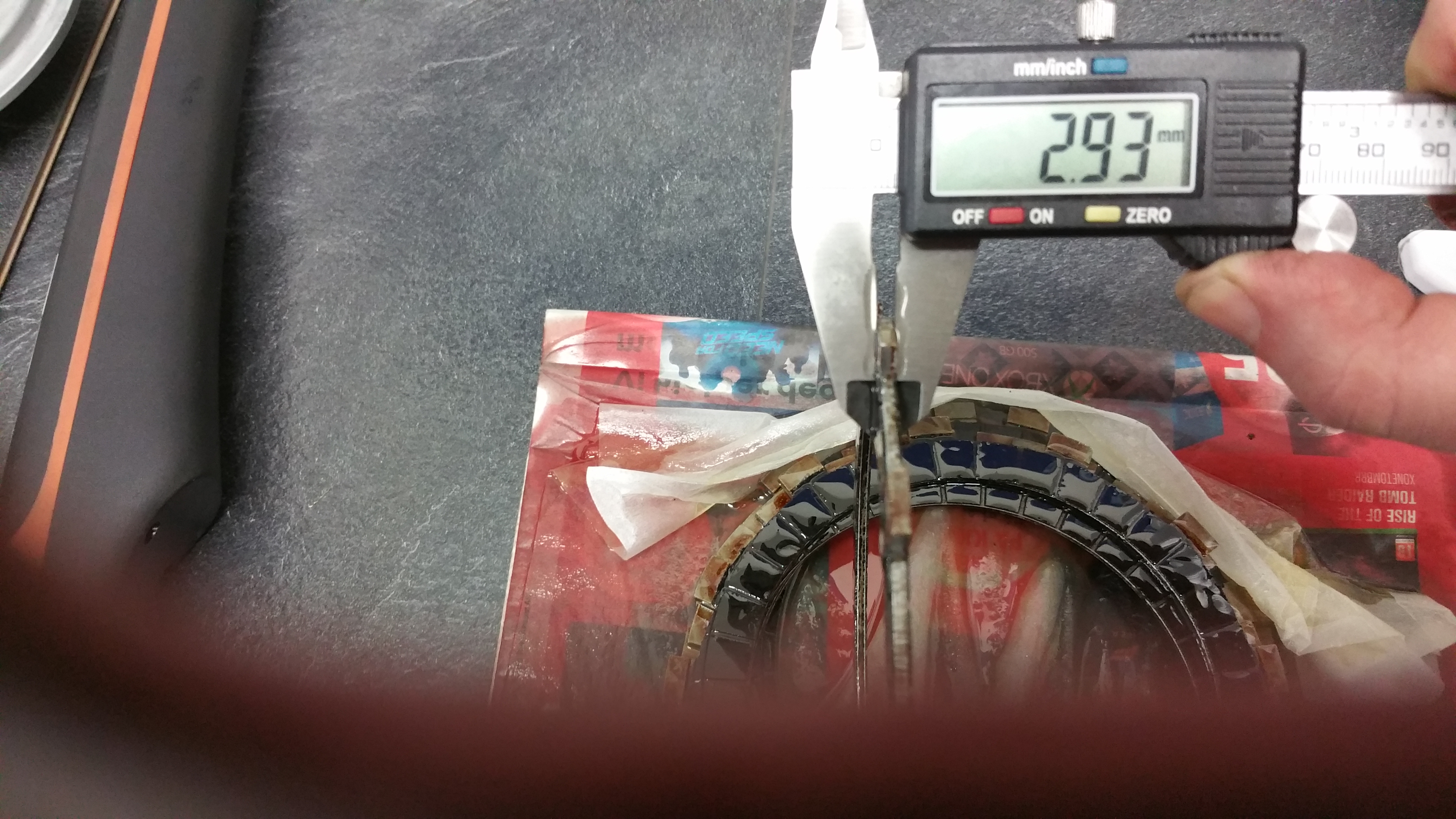
Fig.4.
Make sure the point is open and not closed. If the point is closed you have a short in paralell of the cap.
Use an instrument capable of measuring CAPACITOR. Connect the red test lead from the CAP output to the yellow wire on the capacitor. The black lead to any part at ground level. In fig. 4 the value is 192 nF and is a valid result.
COIL
As mentioned in the beginning of this post the Suzuki coil is actually an electromangnetic transformer and contains two coils. And three of those transformers is needed, one for each spark plug.
What is a the function of an electromagnetic transformer ?
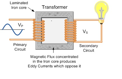
Fig.5
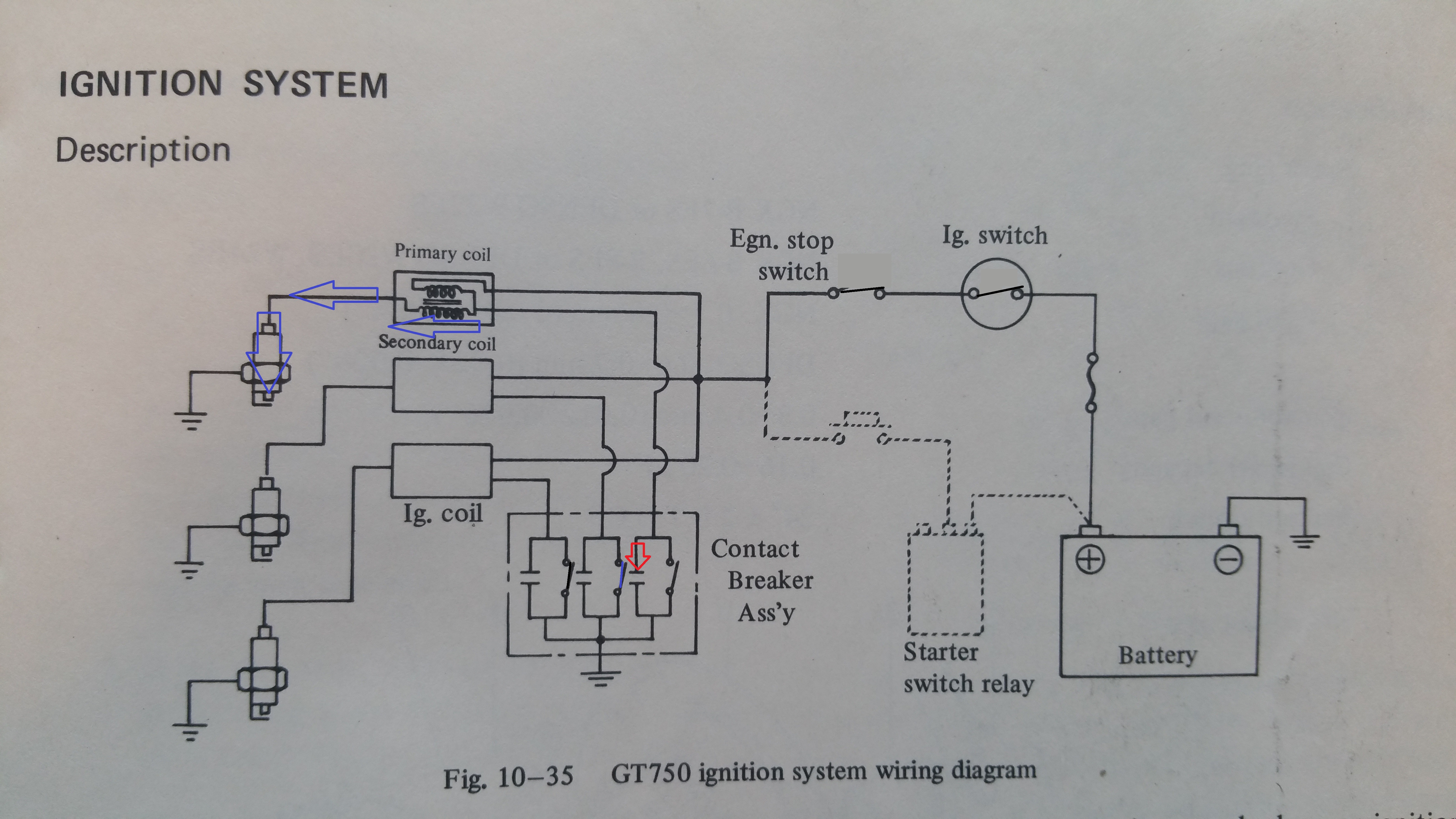
Answer: On the primary side you apply a AC voltage and the windings around the iron core set up an alternating magnetic field. At the secondary side the magnetic fields are throwned across the windings. Whenever an inductor or a wire sees a varation in a magnetic field we have induction of voltage across the wires. And the bulb in fig. 5 can light up. The ratio on numbers for windings define the voltage. If you have 10 times more turns on the primary side compare to the secondary side, the voltage will be 10 times lower on the lamp. And opposite, in the GT750 coil we have more windings on the secondary and transform the voltages up many times
And don’t be sad if you don’t understand why. Einstein didn’t understand it either. No one does, it’s only a fact of physics. And it only happen if we apply AC (alternated voltage) giving an alternated magnetic field. A static magnetic field does not induct any voltage at the secondary side.
In other words, a 12V DC battery gives no voltage at the secondary side. Stop !, that’s what we have in the GT750 electronics, a DC battery and a transformer. Yes, and you don’t get any voltage on the secondary side until you…..cut off the current with the circuit breakers. That’s what we use the points for, cutting a DC current into pieces , making a conversion from DC to AC.
Current into the GT750 coil:
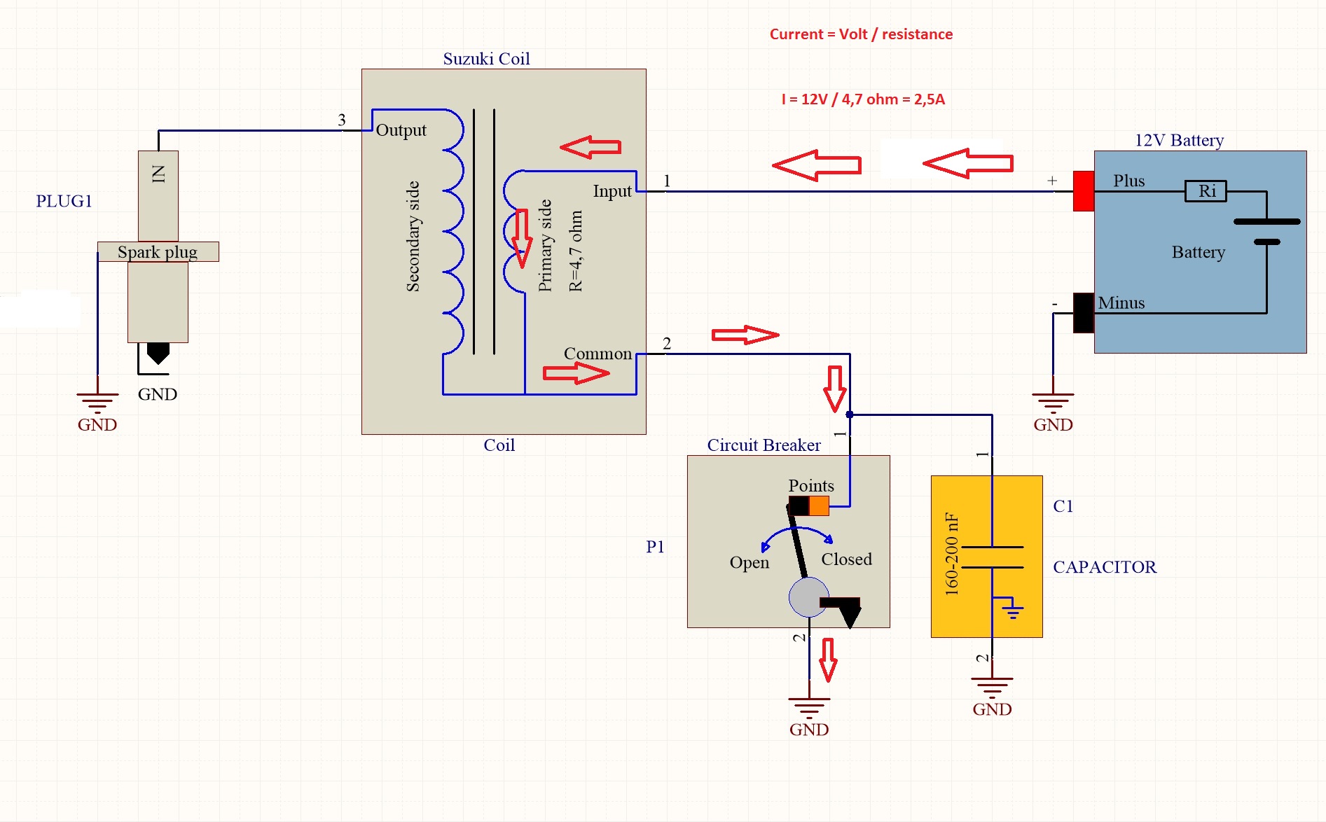
Fig. 6
I measured the DC resistance in the primary side coil to about 4,7 ohm. 12V divided on 4,7 R gives about 2,5 Amps into the coil. This gives a solide magnetic field in the coil but no voltage at the secondary side. When the camshaft hit the circuit breaker and open up the points, the current are cutt off and the magnetic field collaps. This is the change in the field that gives the high voltage at the secondary side. The voltage across the opened point is also very hig but the capacitor in paralell charge up and protect the points from getting worn.
This sequence is also explained in the post “Ignition circuitry”
This is meant to happen 24 deg before BTDC ( Before Top Dead Center ) A detailed explanation of the timing adjustments will come in a separate post
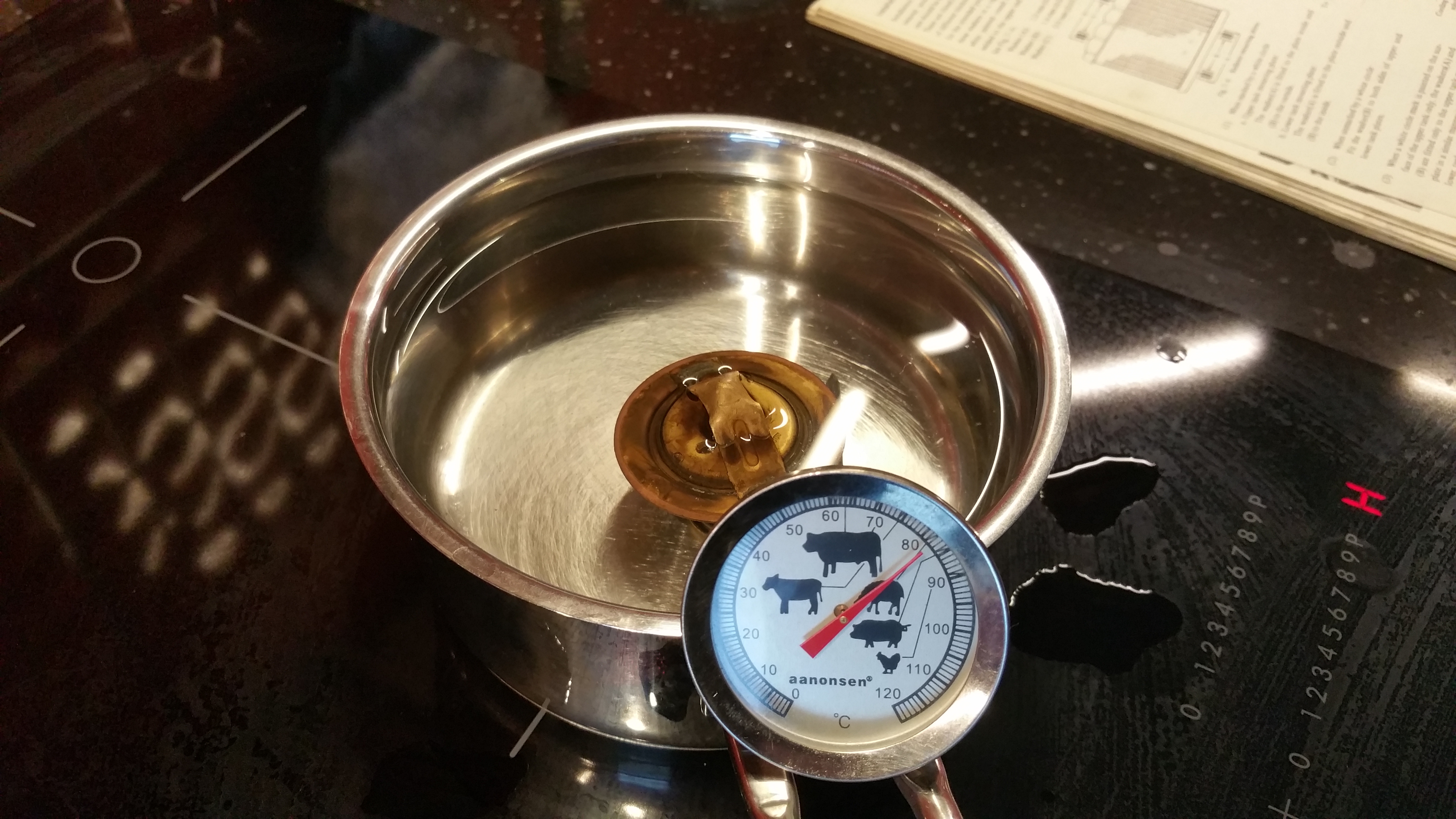
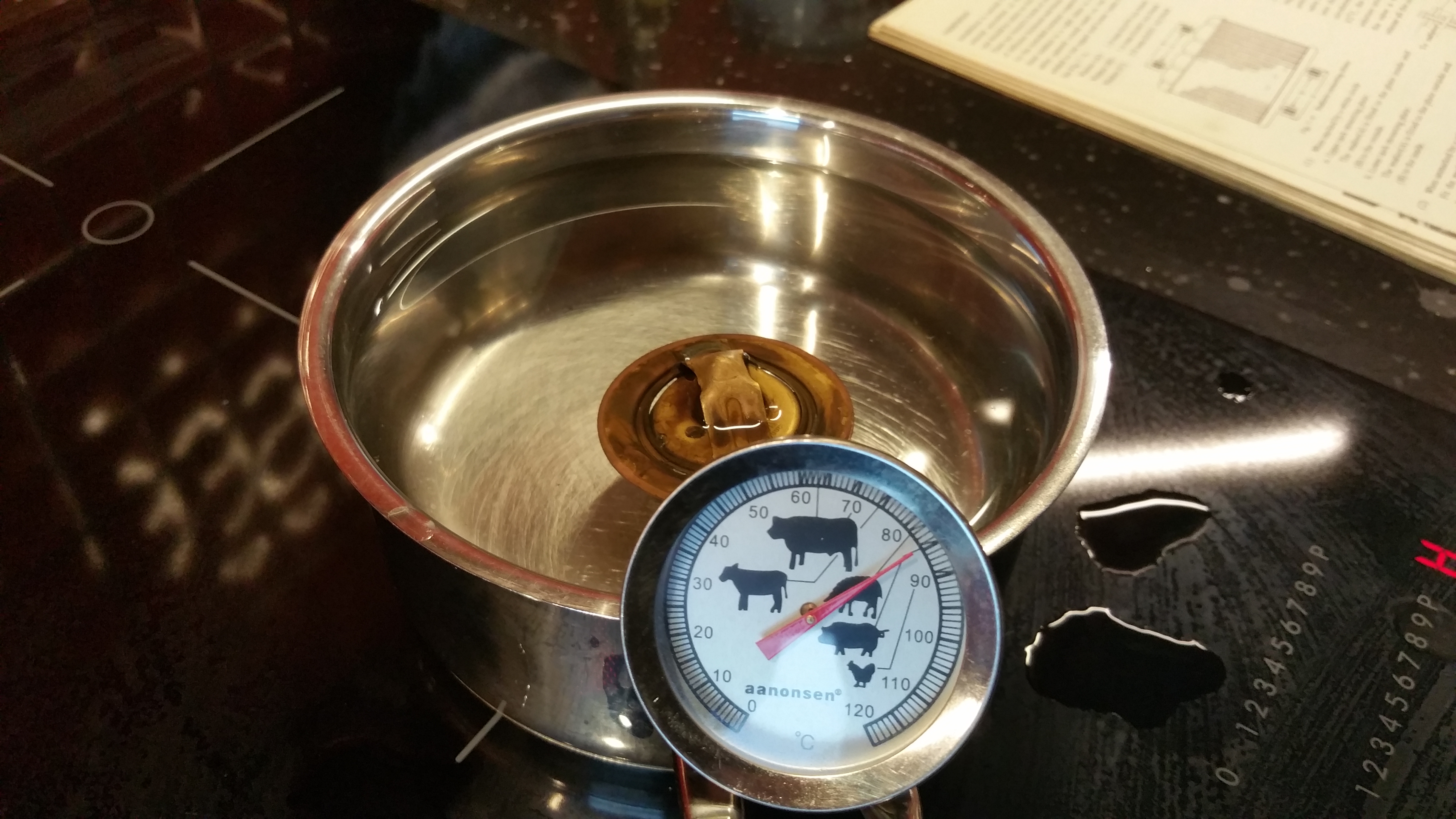
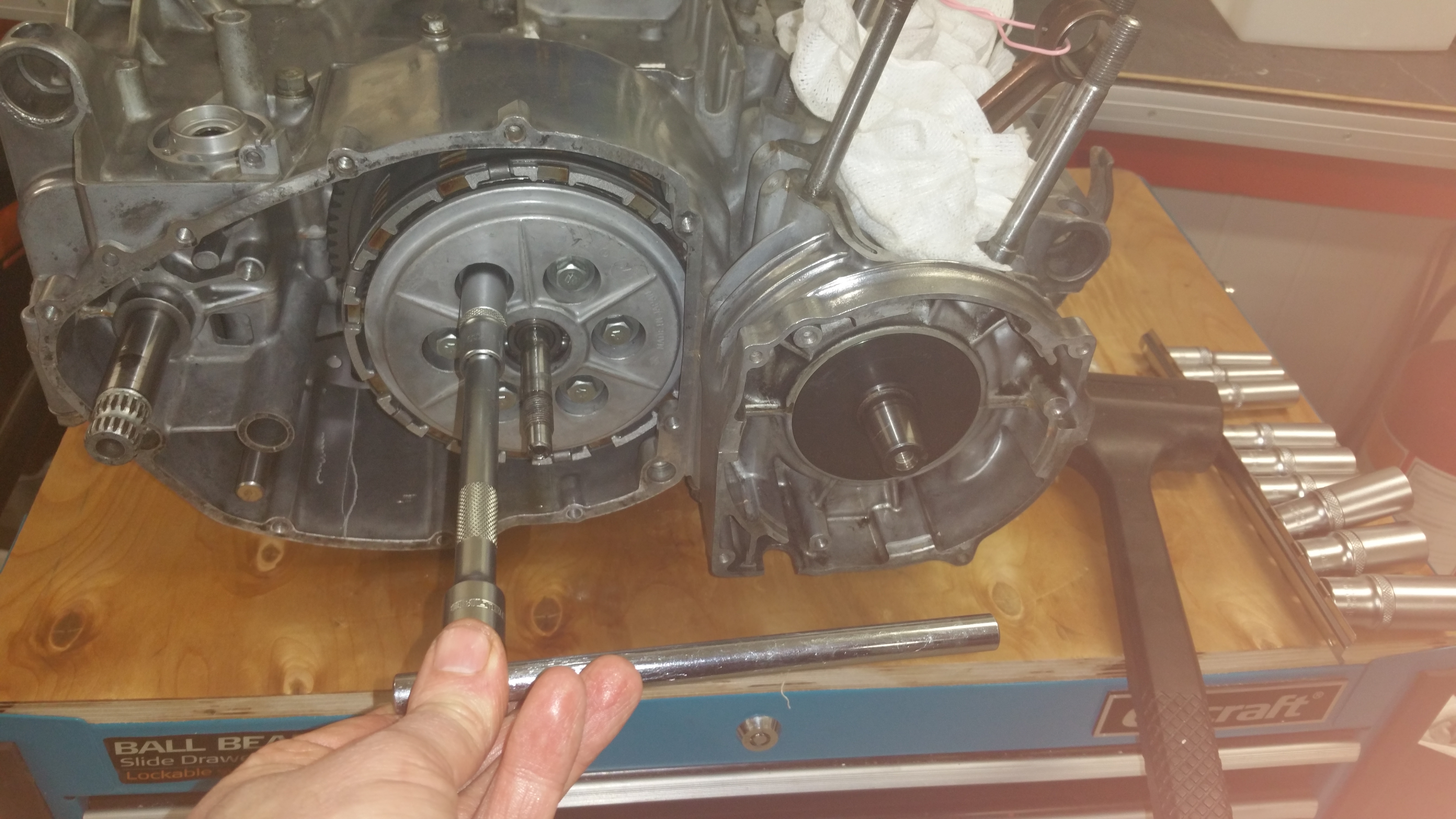
How to measure the coil :
Click on the image for details
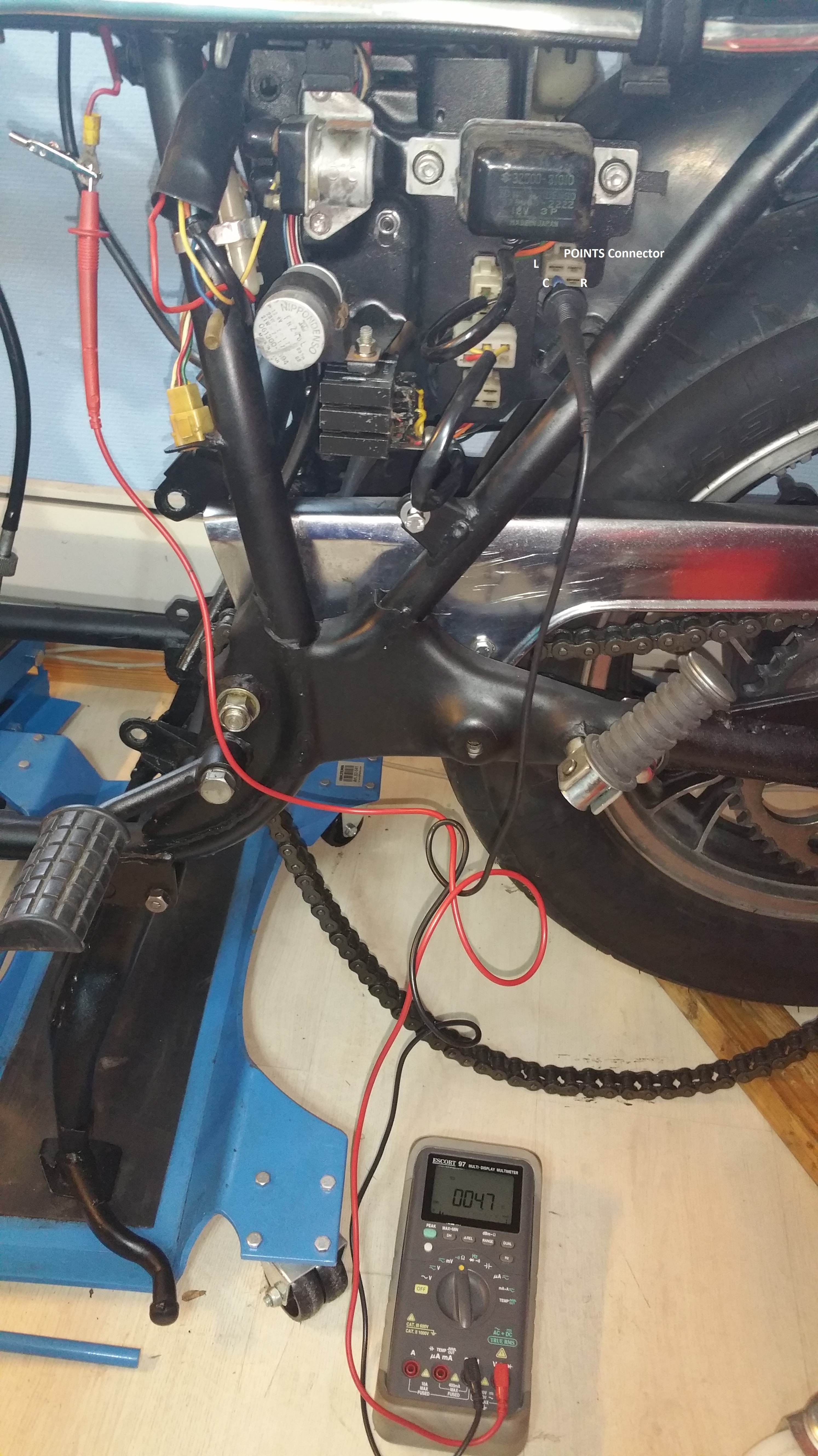
Fig.7
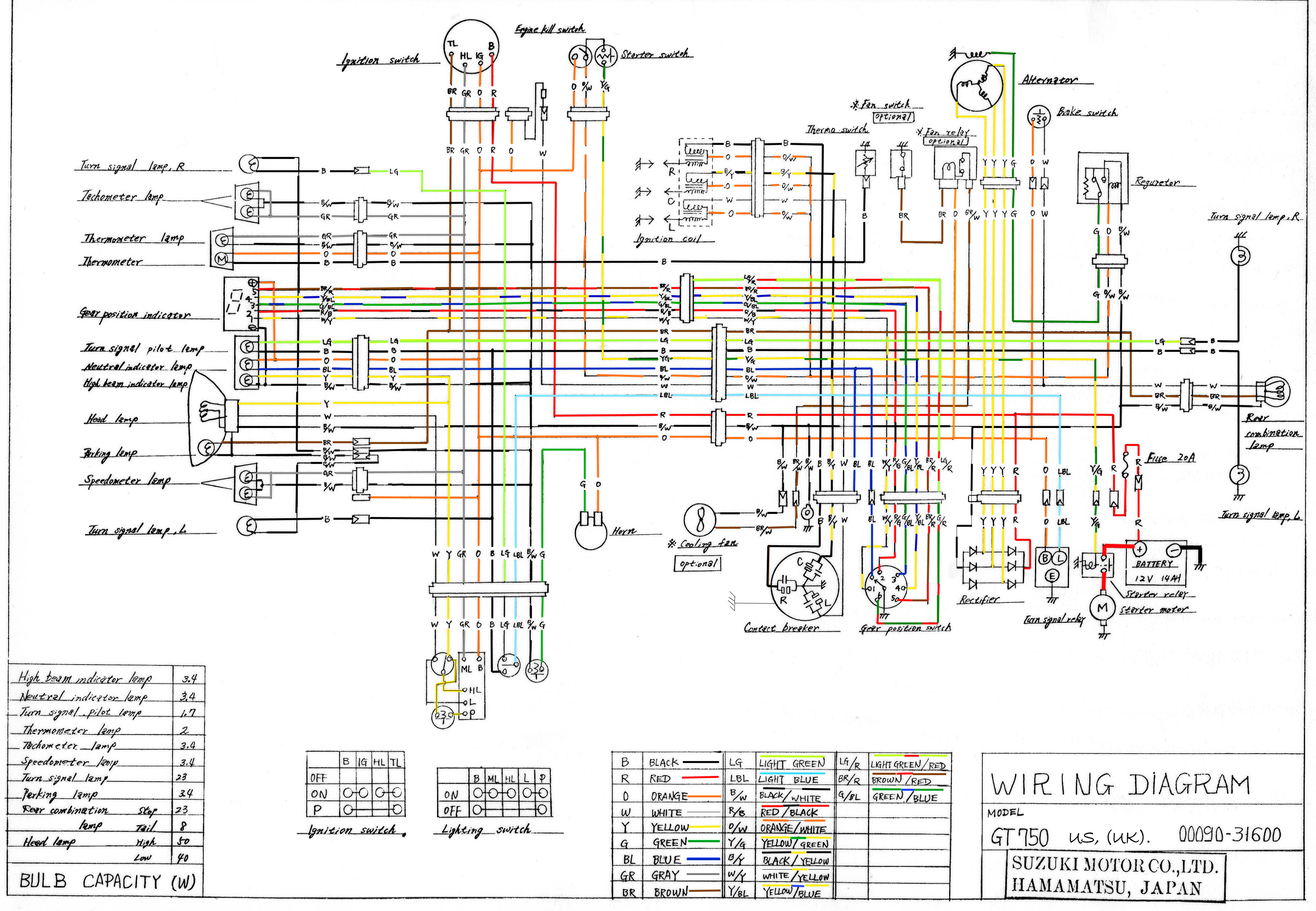
An easy access to all of the three coils is to measure from the side panel and to the positive pole on the battery cable. Remember the signal from the meter has to go through the emergency switch and the ignition switch. I found 4,7 ohm on all of the secondary side coils.
See the wiring diagram and my previous post “Ignition circuitry”
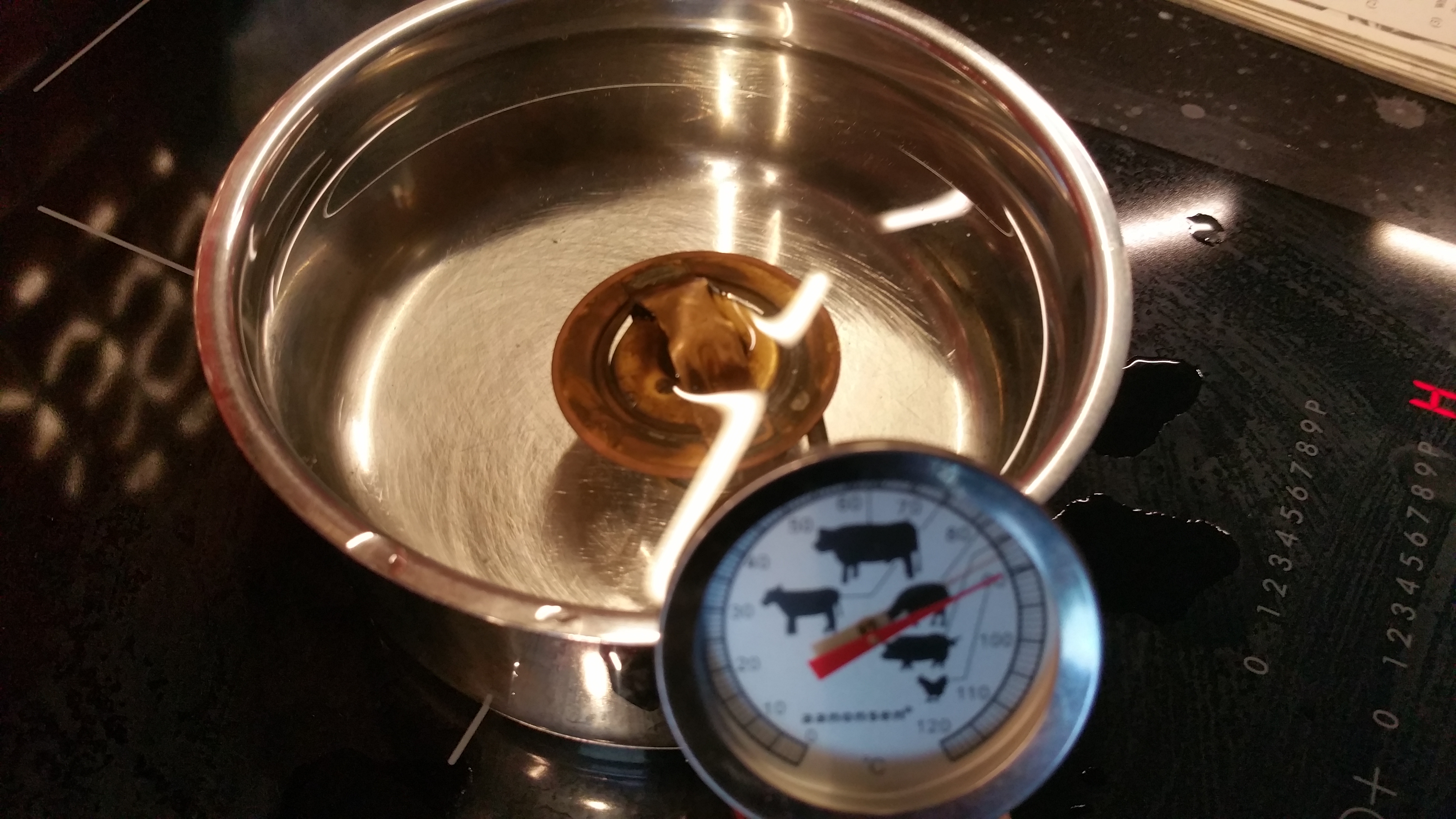
Figure 8. shows another access to the coils:
The orange wire is the common wire for all of the coils. Measure from the orange one and to the White (Left coil ) Black /yellow ( Center coil ) and Black wire for the Right coil.

Fig.8