Regulator
The orange wire is the +battery voltage, but after the ignition switch. The green wire is the +voltage to the rotor and the white and black wire is the GND wire.

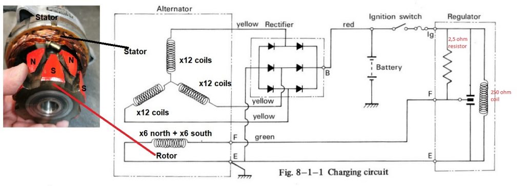
The regulator on GT380 and GT750 works in the same way. The purpose is to control the rotor current and thereby adjust the magnetic field so the generator (alternator) and rectifier gives about the same outputvoltage regardless of the rpm.
The case got sandblasted and repainted. The contact breakers in the relay were sanded a bit to achieve a good connection and the current flow was thereafter tested with a power supply.

The pictures below shows the different stages from 1-3 depending of the voltage to the relay coil.

The diagrams are a bit difficult to read, they are only meant to be a reference for the different stages in the pictures above. Details about the diagram and how it all works are explained in my previous post, the Alternator.