Browse Author: tore@grenasberg.no

Engine Teardown

Step 1, removal of cylinder head:

As always on my blog, click on the images for a more close up detailed view.


Remove all 12 nuts from the cylinder head. Use a rubber hammer to knock it loose.
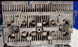
 

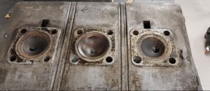
Bottom side of the cylinder head.


Step 2, removal of cylinders:

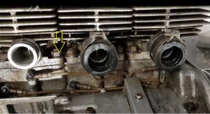
Remove the nuts holding the cylinder.  Four of them for each cylinder, see the yellow arrow.

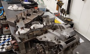
The cylinders should come off quite easy. Three individual ones, not one big block as on the GT750.


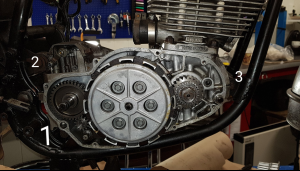
Step 3, removal of clutch :

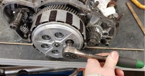
Give the wrench a tap and the bolts should come loose.

Put all the parts together in a safe location so you know where to find them later on.

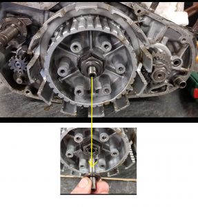
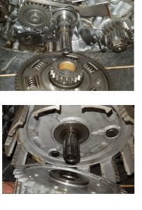
Remove the axle part


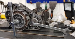
The big nut in the middle can be hard to get off. You somehow have to lock the clutch from spinning too. And of course, bend the lock washer straight before you start.

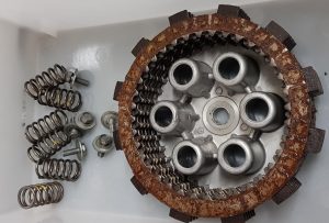
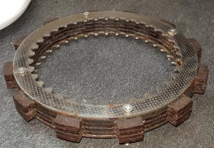
You can buy a tool for this, but I made my own using the rusty part from the clutch. Drilled 3 mm holes and screwed the fiber and metal discs together and put them back into the clutch house.

Like this:


Locked the crank using an extra key and…..hmm, off it went, Phuu !

Keep track of the parts for the assembly process to come later.


Step 4, more parts to be removed:


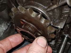
Front sprocket:


Step 5, loosen the crank :

Block the crank using two wooden sticks.
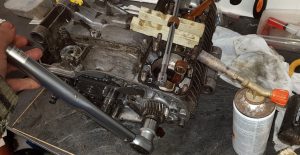
That nut was really hard to remove. Had to use a butane/propane torch and heat up before it came loose.

Keep track of all the parts !


Step 6, rotor removal:

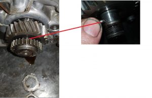
Remove the 8mm axle holding the rotor in place.


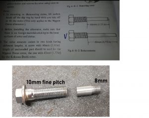
Suzuki recommend in the service manual to use a special tool to pull off the rotor. I don’t have that tool and made therefore another type of tool using my lathe. I have also heard some concerns about the Suzuki tool causing damages on the 8mm threads at the end of the crank.  Using an 8mm insert as shown in the picture might therefore be a better option.

Any inserts can be used as long as they have 8mm threads.

The bolt to push on the insert causing the rotor to be pulled off must be 10mm fine pitch. I took one of the bolts made for the GT750 exhaust clamping at the rear.

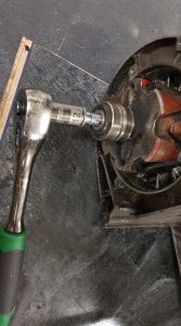
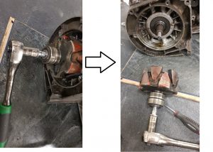
And off it goes 🙂


Step 6, splitting the crankcase:

As always, it’s a good idea to store all removed bolts on a cardboard, a simple drawing showing the placements. Since we have entered 2019 I took it one step further and printed out an image of the top and bottom side and stamped it to the cardboard plate. Easy to keep track of all the bolts.

9 bolts on the top side and 18 on the bottom side.


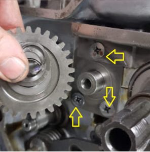
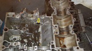
Important : In addition to the bolts on top and bottom you have to remove this three screws since they clamp the top and bottom side together. They are hard to get loose. Probably fastened with loctite glue. I had to use the butane torch and a impact driver. Don’t try without using the impact driver.

A gentle touch using a rubber hammer will get it loose.


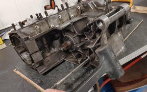
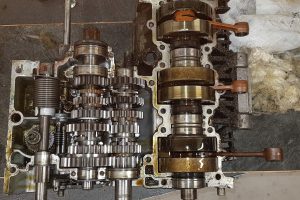
All open…

First impression: could have been worse….

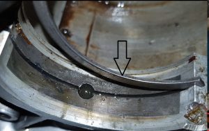
The crank needs rebuilding, but the gears looks good.


Step 7, removing parts:


Again, use the propane/butane torch to heat up and knock on the impactdriver to get the screws loose.

And keep track of the parts.

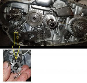
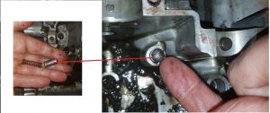
Take care, the parts will fly away when retracted. Not easy to put together again. I did the same on my GT750 and hopefully it’s all described on my blog how to do it … 🙂

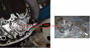
Don’t miss this part while removing the crank.


And this:


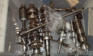
Stored in boxes for later inspection.


Use a pipe to drive out the needle bearing

After a proper cleaning the crankcase will be powder blasted, but not today.
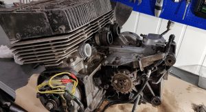
Teardown

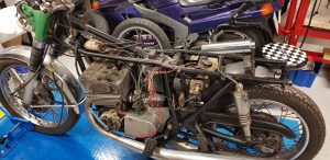
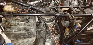
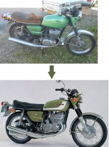
The work to take apart the GT380 J/K model has started.

Day 1:

Aiming for a full teardown and rebuild.A lot of work to be done, but that was part of the plan. Learning by doing…and hope the result will look good.


Step 1, get going: 


The pipes are mounted wrong, off they go.

Wrong


Correct


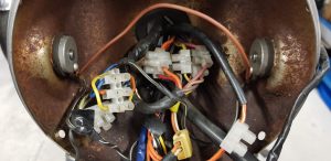
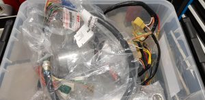
The  old wiring is just horrible…. Luckily, I got hold of brand new wiring loom, phuu 🙂


Step 2, air filter and carbs:

Service manual says: Remove the left carb before removing the air filter, and I did so:


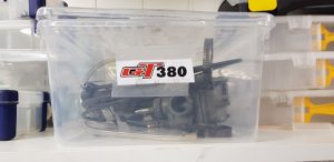
Dismounted the carburetors and laid them in a box for later rebuild

Step 3, organize :

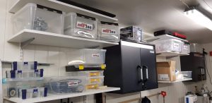
Will use plastic boxes and bags to organize the parts. + stickers in the bags telling what it is.

Day 2:

Do some thinking before acting…..

Step 1:

Thinking done, loose and remove  no1 and no  2 bolts.


Step 2:

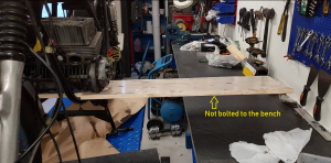
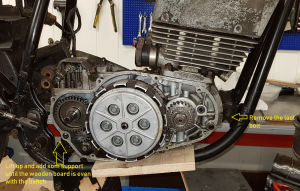
Since the engine is only connected to the no 3 bolt the engine can be lifted to allow a wooden board to slide in.

Step 3:

Remove  no 3 bolt.

Lift the engine to and align using a piece of wood in the left hand side until the board is even with the bench.


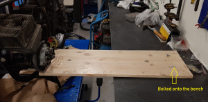
Lower the MC lifter and bolt the board to the bench.


Step 4:

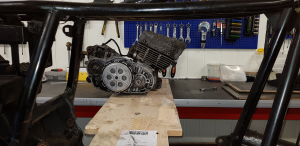
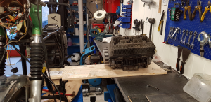
Continue to lower the lifter until the engine can move freely away from the brackets.

Slide the engine onto the bench and you are done. 🙂 🙂


A new look :)

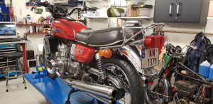
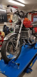
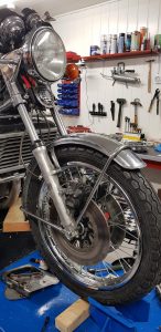
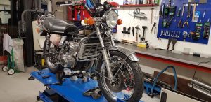
Had to put the tank back on and take some pictures with the new GT wheels mounted.

Looks nice with original wheels on 🙂


The video on the PC below shows the bike with the old GS wheels mounted

Wheels mounted

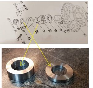
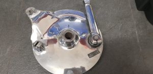
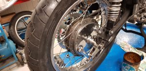
A bit slow progress. Had to make parts on my lathe to be able to fit the rear wheel. Had plans to reuse the spacers from the GS wheel, but nothing was able to fit. Main reason : The GS axle was 17mm and the GT is 20mm.
Finally, both wheels are mounted on the bike. 🙂

At last, both wheels are on. GT wheels looks so much better compared to the GS wheels.

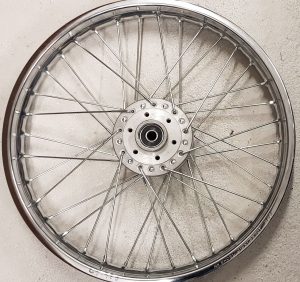
Spokes adjustments

Got some help today showing me how to adjust the spokes. Jan Hansen and Thor Haugland came all the way from Kristiansand help me on this.

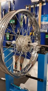
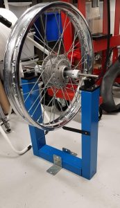
A simple homemade wheel jig

Step 1

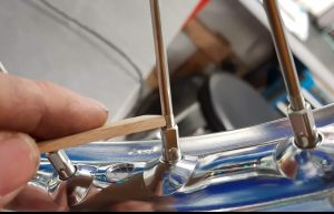
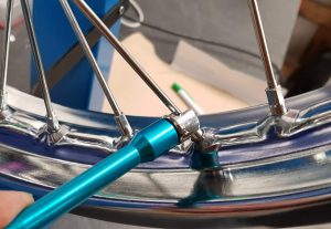
Adjust all the spokes to the same length, see the picture. I used a piece of stick as a template to get the same distance all over. Adjust the nipples by hand at this point. Make sure you have the same number of threads by comparing the thickness of the stick

Spin the wheel and watch the height. There should be not much play in the height of the rim if all the spokes are evenly adjusted.

Step 2

Tighten the spokes:

Turn the nipple 1/4 of a turn on all of the spokes. Continue until you start to feel some resistance. Not much torque should be applied at this point. Remember to spin the wheel and only 1/4 of a turn on each spoke.

Step 3

Time to check the play at the side:

Spin the wheel and use a whiteboard marker to define the area where you see the largest clearance to the reference stick. Make two lines, the start and stop of the area.

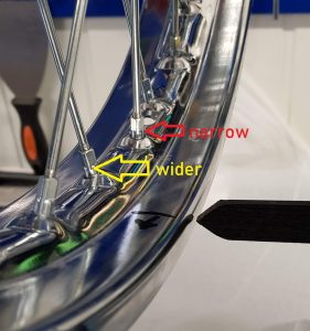
Adjust all spokes in the area to adjust the proper way. As the yellow arrow shows, the outer one to widen the gap and the inner one ( red arrow) to narrow the gap.
Repeat this procedure until you are down to 1-2mm play. Suzuki allows up to 3mm offset.
Step 4

Final adjustments

Continue with step 3 until you have to apply some torque to turn the nipples around.

This is the time when you have to trust your basic instinct. Do not overtighten the nipples !

If the nipple feels tight go further to the next one. Make sure you have about the same tension on all spokes. You can knock on the spokes and if one of them are to loose you will hear a different sound.

This is how I did it with help from Jan giving me advice all the time.
Am I lucky or something ? Looks like the wheel came out pretty well 🙂

GT 750 Front wheel, spokes mounting

For the frist time I’m going to build the front wheel with new spokes. Will be the same for both GT750 and Gt380.

Click on the images for a close up view.

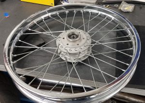
All spokes mounted, but how?  Will try to give a detailed guidance below:

Step 1

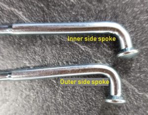
Sort the spokes. There are 18 spokes to be mounted on the inner side of the hub and 18 spokes for the outer side

The spokes for the outer side of the hub has more bending at the end, see the picture above.

Step 2

Study the rim:

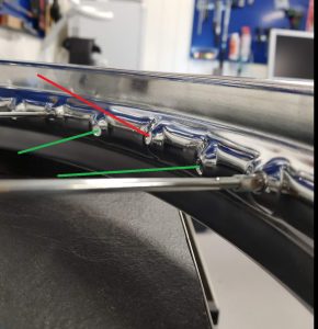
The mounting holes in the rim are aligned to left and right to fit with the corresponding side of the hub. The change in direction is done for every second hole. As the picture shows with red and green lines.

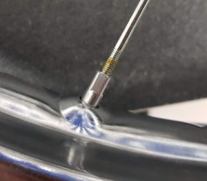
There is also angle pointing from the rim to the center of the hub. Should be easy to spot but if you don’t know this part will go wrong while mounting the spokes.


Step 3

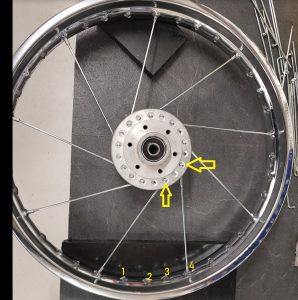
Always start with the inner side of the hub and find a the right corresponding hole in the rim. Correct angle and direction ( left or right ) explained in step 2. Repeat the same for the next spoke counting 4 holes as shown in the picture. Fasten the spoke by mounting the nipple at the end, only some few turns. You can also apply some grease.

Complete the mounting all 9 spokes on this side. Turn the wheel and do the next 9 spokes on the other side of the wheel and still at the inner side of the hub.

Watch the first picture with all 36 spokes mounted before you start with the 9 inner side spokes at the next side of the wheel. Check the position in the hub carefully against the picture and find the right corresponding hole in the rim.

If you mount all 18 spokes on one side first ( inner and outer) you will not be able to fit the spokes at the other side.


Step 4

Mounting the spokes at the outer side of the hub

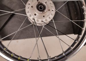
If you count in the same way as in step 3, the no 6 will be the right hole in the rim. See the black line in the picture and continue in the same way for every 4th hole.

If you are in doubt, have a close look at the first picture again.

Do both sides of the wheel and you are done 🙂

The next step, the adjustments will be uploaded in another post.